Table of Contents
Advertisement
Quick Links
SECURITY DOOR CONTROLS ■ WWW.SDCSECURITY.COM
[t] 800.413.8783 ■ 805.494.0622 ■ E-mail: service@sdcsecurity.com ■ 801 Avenida Acaso, Camarillo, CA 93012 ■ PO Box 3670, Camarillo, CA 93011
MODELS
S6000DE
Verbal Exit Instructions or
Alarm Tone Only and
Digital Countdown Display
Application:
When unauthorized egress is initiated SDC Exit Check
the person exiting must wait while personnel or security responds. The exit device unlocks after 15 seconds have elapsed, permitting
egress. When powered by a fire control supervised power supply, the exit device will allow egress immediately in an emergency.
The integral verbal message, digital countdown display and sign provide comprehensive and clear instructions of the door operation for
persons without prior knowledge of the exit delay, including the sight and hearing impaired.
The digital keypad eliminates the need to carry and locate keys for reset and bypass functions.
Features:
Egress Delay
15 or 30 second exit delay
1 or 2 second nuisance delay
Built-In 3 Function keypad
Alarm and lock reset
1 to 30 second bypass
Sustained bypass
Additional key switch optional
Control Inputs
1 to 30 second request-to-exit and
bypass input with anti-tailgate and
jumper selectable door prop alarm.
Reset
Trigger Modes
Egress alarm triggered by Push Bar
Trigger input from external device
field selectable (N/O or N/C)
P:\INST INSTRUCTIONS\Delayed Egress\INST-6000\INST-S6000DE_KDE
INSTALLATION INSTRUCTIONS
S6000DE / S6000KDE
DELAYED EGRESS DEVICE
S6000KDE
Rim Mount, Surface Vertical Rod, or Mortise Exit Device
NOTE: SDC 600 Series Power Supply required
®
delays egress through the door for 15 seconds (or 30 seconds). Meanwhile,
Built-In Annunciation
Armed mode
Nuisance mode
Irreversible egress mode
Release mode
Digital countdown mode
Field selectable voice notification or tone
Field selectable male voice with security
message or female voice with safety
message
Monitoring Outputs
Egress initiation status
Secure/unsecure status
Choice of Mounting
Recessed mounted
(3 gang metal plaster ring included)
Surface mounted with optional 3 gang
box (DEC-J)
Optional shroud (SHD-J) to be used with
DEC-J surface box.
Exit Check
Code Compliance
Rev D
11-20
Page 1
®
Applications include:
Restricting the egress of wandering patients
for their own safety.
®
HUGS
Infant Protection System
compatibility
Restricting the egress of commercial center
patrons for security application needs.
Controlling pedestrian traffic in
transportation facilities, including airport
jetways and tarmacs
Reducing Shoplifting and Employee Theft
IFC International Fire Code
IBC International Building Code
NFPA 101 Life Safety Code
NFPA 1 Uniform Fire Code
California Building Code
Field selectable automatic or manual
power up after emergency release or
power loss. Use of manual power up
complies with California Building Code
(OSHPD) requirements.
Any suggestions or comments to this instruction or
product are welcome. Please contact us through
our website or email engineer@sdcsecurity.com
Advertisement
Table of Contents

Related Manuals for SDC S6000DE


Summary of Contents for SDC S6000DE
- Page 1 Application: ® When unauthorized egress is initiated SDC Exit Check delays egress through the door for 15 seconds (or 30 seconds). Meanwhile, the person exiting must wait while personnel or security responds. The exit device unlocks after 15 seconds have elapsed, permitting egress.
- Page 2 SECURITY DOOR CONTROLS ■ WWW.SDCSECURITY.COM [t] 800.413.8783 ■ 805.494.0622 ■ E-mail: service@sdcsecurity.com ■ 801 Avenida Acaso, Camarillo, CA 93012 ■ PO Box 3670, Camarillo, CA 93011 101-DE/101-KDE Operational Description The door is closed and secured by latching hardware. The model 101-DE/101-KDE Exit Check controller sends power to the Delayed Egress Panic Device to lock the door in the secured position.
- Page 3 WITH KEY CYLINDER IN PROPER POSITION INSIDE SWITCH BLOCK, TIGHTEN THE SET SCREW TO LOCK CYLINDER IN PLACE. 1-1/4” KEY CYLINDER REQUIRES COLLAR Power Supply SDC 600 Series 1-1/8” KEY CYLINDER 2 Wires 7185SC1-26D-KD RECESSED MOUNTING 4 Wires (PTH-4) or...
- Page 4 SECURITY DOOR CONTROLS ■ WWW.SDCSECURITY.COM [t] 800.413.8783 ■ 805.494.0622 ■ E-mail: service@sdcsecurity.com ■ 801 Avenida Acaso, Camarillo, CA 93012 ■ PO Box 3670, Camarillo, CA 93011 RECOMMENDED MOUNTING PROCEDURE USE 1-1/4” SCREWS SUPPLIED WITH WALL MOUNT FRAME TO HANG UNIT TEMPORARILY FOR WIRING PURPOSES SLIDE PACKING FOAM BETWEEN WALL AND UNIT TO PREVENT DAMAGE TO FACEPLATE...
- Page 5 Power Supply JUMPER J1 (DOOR PROP) J1 INSTALLED: The S6000DE/KDE will enter the alarm mode if the door is held open past the request to exit period. J1 REMOVED: The S6000DE/KDE will remain unlocked if the door is held open past the request to exit period. No alarm will sound.
-
Page 6: Keypad Programming
SECURITY DOOR CONTROLS ■ WWW.SDCSECURITY.COM [t] 800.413.8783 ■ 805.494.0622 ■ E-mail: service@sdcsecurity.com ■ 801 Avenida Acaso, Camarillo, CA 93012 ■ PO Box 3670, Camarillo, CA 93011 System Operation POWER-UP UNLOCKED POWER-UP LOCKED The door is unlocked. To enter the The door is Armed Mode, turn the keyswitch to locked and Reset or enter the Reset Code... -
Page 7: Entering Programming Mode
SECURITY DOOR CONTROLS ■ WWW.SDCSECURITY.COM [t] 800.413.8783 ■ 805.494.0622 ■ E-mail: service@sdcsecurity.com ■ 801 Avenida Acaso, Camarillo, CA 93012 ■ PO Box 3670, Camarillo, CA 93011 Changing the Master Code User 1 is always used as the Master Code and is required to access keypad programming. The Factory Default Master Code is “1234 ”. -
Page 8: Connecting Optional Accessories
SECURITY DOOR CONTROLS ■ WWW.SDCSECURITY.COM [t] 800.413.8783 ■ 805.494.0622 ■ E-mail: service@sdcsecurity.com ■ 801 Avenida Acaso, Camarillo, CA 93012 ■ PO Box 3670, Camarillo, CA 93011 Connecting to a Infant/Patient Monitoring System 1. Locate jumper [J6] (above the IBO input). Verify that it is NOT installed across both pins. 2. -
Page 9: Installation Instructions
SECURITY DOOR CONTROLS ■ WWW.SDCSECURITY.COM [t] 800.413.8783 ■ 805.494.0622 ■ E-mail: service@sdcsecurity.com ■ 801 Avenida Acaso, Camarillo, CA 93012 ■ PO Box 3670, Camarillo, CA 93011 INSTALLATION INSTRUCTIONS S6100 SERIES PANIC/FIRE EXIT DEVICES These instructions are presented a in step by step sequence. -
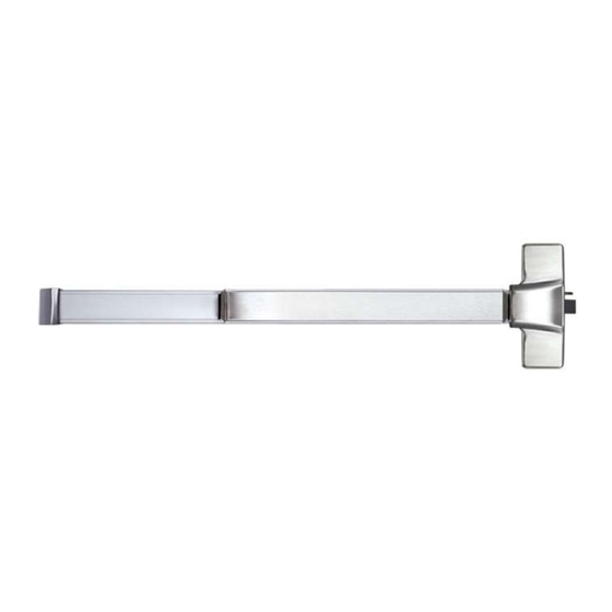
Page 10: Designation Of Parts
SECURITY DOOR CONTROLS ■ WWW.SDCSECURITY.COM [t] 800.413.8783 ■ 805.494.0622 ■ E-mail: service@sdcsecurity.com ■ 801 Avenida Acaso, Camarillo, CA 93012 ■ PO Box 3670, Camarillo, CA 93011 End Cap Bracket A. DESIGNATION OF PARTS Chassis End Cap Dogging Device Chassis (Fire Exit Hardware is not Equipped with this device) Chassis Cover Push Bar... - Page 11 SECURITY DOOR CONTROLS ■ WWW.SDCSECURITY.COM [t] 800.413.8783 ■ 805.494.0622 ■ E-mail: service@sdcsecurity.com ■ 801 Avenida Acaso, Camarillo, CA 93012 ■ PO Box 3670, Camarillo, CA 93011 STOP LINE D. INSTALL STRIKE TO FRAME Jamb 1. Place strike over the drilled holes, and attach it to the jamb or mullion with the supplied screws.
-
Page 12: Install Covers
SECURITY DOOR CONTROLS ■ WWW.SDCSECURITY.COM [t] 800.413.8783 ■ 805.494.0622 ■ E-mail: service@sdcsecurity.com ■ 801 Avenida Acaso, Camarillo, CA 93012 ■ PO Box 3670, Camarillo, CA 93011 Mark mounting holes through End Cap Bracket after device is level NOTE: The Device bar has 3 different lengths; Standard 3' Door Device = Approx 33"...
Need help?
Do you have a question about the S6000DE and is the answer not in the manual?
Questions and answers