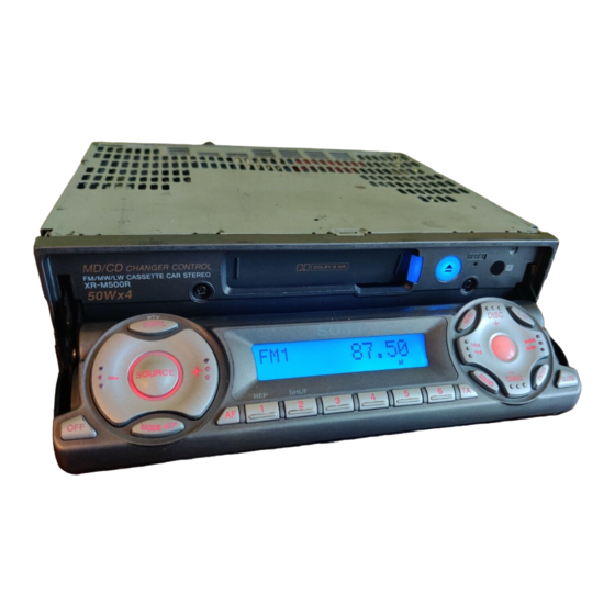
Sony XR-M500R Service Manual
Fm/am (mw/lw) cassette car stereo
Hide thumbs
Also See for XR-M500R:
- Operating instructions manual (212 pages) ,
- Service manual (66 pages) ,
- Installation/connections (2 pages)
Table of Contents
Advertisement
Quick Links
QQ
3 7 63 1515 0
SERVICE MANUAL
Dolby noise reduction manufactured under license from
Dolby Laboratories Licensing Corporation.
"DOLBY" and the double-D symbol ; are trademarks
of Dolby Laboratories Licencing Corporation.
AUDIO POWER SPECIFICATIONS (US model)
TE
L 13942296513
POWER OUTPUT AND TOTAL HARMONIC DISTORTION
19 watts per channel minimum continuous average power into
4 ohms, 4 channels driven from 20 Hz to 20 kHz with no more
than 1% total harmonic distortion.
Other specifications
Cassette player section
Tape track
Wow and flutter
Frequency response
Signal-to-noise ratio
Cassette type
TYPE II,
TYPE I
Tuner section
FM
Tuning range
Antenna terminal
Intermediate frequency
Usable sensitivity
Selectivity
www
.
http://www.xiaoyu163.com
XR-M500R/M550
4-track 2-channel stereo
0.08 % (WRMS)
30 – 20,000 Hz
Dolby B NR
Dolby NR off
IV
67 dB
61 dB
64 dB
58 dB
87.5 – 108.0 MHz (XR-M500R)
87.5 – 107.9 MHz (XR-M550)
External antenna connector
10.7 MHz/450kHz
8 dBf
75 dB at 400 kHz
FM/AM (MW/LW) CASSETTE CAR STEREO
x
ao
u163
y
i
http://www.xiaoyu163.com
2 9
8
Photo: XR-M550
Model Name Using Similar Mechanism
Tape Transport Mechanism Type
SPECIFICATIONS
Q Q
3
6 7
1 3
1 5
Signal-to-noise ratio
Harmonic distortion at 1 kHz
Separation
Frequency response
MW/LW (XR-M500R)
Tuning range
Aerial terminal
Intermediate frequency
Sensitivity
AM (XR-M550)
Tuning range
Antenna terminal
Intermediate frequency
Sensitivity
co
.
9 4
2 8
US Model
Canadian Model
AEP Model
UK Model
NEW
MG-25E-136
0 5
8
2 9
9 4
2 8
66 dB (stereo),
72 dB (mono)
0.6 % (stereo),
0.3 % (mono)
35 dB at 1 kHz
30 – 15,000 Hz
MW: 531 – 1,602 kHz
LW: 153 – 279 kHz
External aerial connector
10.7 MHz/450 kHz
MW: 30 µV
LW: 40 µV
530 – 1,710 kHz
External antenna connector
10.7 MHz/450 kHz
30 µV
– Continued on next page –
m
9 9
XR-M550
XR-M500R
9 9
Advertisement
Table of Contents

Related Manuals for Sony XR-M500R


Summary of Contents for Sony XR-M500R
- Page 1 Tuner section Intermediate frequency 10.7 MHz/450 kHz MW: 30 µV Sensitivity LW: 40 µV Tuning range 87.5 – 108.0 MHz (XR-M500R) 87.5 – 107.9 MHz (XR-M550) AM (XR-M550) Antenna terminal External antenna connector Tuning range 530 – 1,710 kHz Intermediate frequency 10.7 MHz/450kHz...
-
Page 2: Table Of Contents
Speaker impedance 4 – 8 ohms Maximum power output 50 W × 4 (at 4 ohms) GENERAL General Location of Controls (XR-M500R) ........ 4 Outputs Audio output (2) (M500R) Setting the Clock ............. 4 Audio output (3) (M550) Changing the Sound and Display Setting ....... 4... -
Page 3: Servicing Notes
There are four types of main board in according of destination for The front panel opens to the bottom of main unit. XR-M500R. In performing the repair, place the main unit on the base having the height exceeding 1 cm. -
Page 4: Location Of Controls (Xr-M500R)
SECTION 2 This section is extracted from instruction manual. GENERAL 3 7 63 1515 0 (XR-M500R) Location of controls Security side qk TA button 16, 17, 18 The corresponding buttons of the unit control the same functions as those on ql SOUND button the card remote commander. -
Page 5: Locations Of Controls (Xr-M550)
http://www.xiaoyu163.com 3 7 63 1515 0 (XR-M550) L 13942296513 u163 http://www.xiaoyu163.com... -
Page 6: Installation (Xr-M500R)
Säkerhetsföreskrifter Precauções •If you mount other Sony equipment with this •Si monta otro equipo Sony con esta unidad, es •Om du monterar annan Sony-utrustning till •É preferível montar este aparelho na posição unit, it is better to mount this unit in the lower preferible montar esta unidad en la posición más... - Page 7 http://www.xiaoyu163.com 3 7 63 1515 0 (XR-M550) L 13942296513 u163 http://www.xiaoyu163.com...
-
Page 8: Connections (Xr-M500R)
3 7 63 1515 0 (XR-M500R) Connections Conexiones Anslutning Ligações Cautions Precauciones Säkerhetsföreskrifter Cuidado •This unit is designed for negative earth 12 V DC •Esta unidad ha sido diseñada para alimentarse •Denna bilstereo är endast avsedd för anslutning •Este aparelho foi concebido para funcionar operation only. - Page 9 If the supplied power connecting cord can not Felaktig anslutning kan skada bilen. Kontakta be used with your car, consult your nearest Sony närmaste Sony-återförsäljare om den medföljande dealer. strömkabeln inte passar till din bil.
- Page 10 http://www.xiaoyu163.com 3 7 63 1515 0 Power connection diagram Diagrama de conexión de Strömanslutningsschema Diagrama de ligação de corrente alimentación Auxiliary power connector may vary depending Typen av yttre strömanslutning varierar från bil O conector auxiliar de corrente pode variar de on the car.
- Page 11 http://www.xiaoyu163.com 3 7 63 1515 0 Connection diagram Diagrama de conexiones Kopplingsschema Diagrama de ligações Equipment used in illustrations Equipo utilizado en las ilustraciones Utrustning som visas i illustrationer Equipamento utilizado nas ilustrações (not supplied) (no suministrado) (medföljer inte) (não fornecido) Front speaker Rear speaker Power amplifier...
-
Page 12: Connections (Xr-M550)
http://www.xiaoyu163.com 3 7 63 1515 0 (XR-M550) L 13942296513 u163 http://www.xiaoyu163.com... - Page 13 http://www.xiaoyu163.com 3 7 63 1515 0 L 13942296513 u163 http://www.xiaoyu163.com...
- Page 14 http://www.xiaoyu163.com 3 7 63 1515 0 L 13942296513 u163 http://www.xiaoyu163.com...
-
Page 15: Disassembly
http://www.xiaoyu163.com SECTION 3 DISASSEMBLY 3 7 63 1515 0 • See page 3 for Servicing Notes. Note: Follow the disassembly procedure in the numerical order given. MECHANISM DECK (MG-25E-136) 1 screw flexible board Note: Don't pull out flexible board from front panel ass’y. 1 screw 2 front panel ass'y L 13942296513... - Page 16 http://www.xiaoyu163.com 3 7 63 1515 0 FRONT PANEL ASS’Y 1 cover (flexible) 2 flexible board (CN402) • Note for Installation of Flexible Board 2 flexible cover 1 Set the flexible board to be at the position in the figure. 3 front panel ass'y L 13942296513 MOTOR BLOCK ASS’Y, CAM (R) ASS’Y 4 screw...
- Page 17 http://www.xiaoyu163.com 3 7 63 1515 0 SUB PANEL (XR) SUB ASS’Y 1 flexible board 2 screw (CN601) (PTT2.6 × 6) 3 sub panel (XR) sub ass'y 2 screw 2 two screws (PTT2.6 × 6) (PTT2.6 × 6) L 13942296513 MAIN BOARD 1 two screws (PTT2.6 ×...
- Page 18 http://www.xiaoyu163.com 3 7 63 1515 0 HEAT SINK 2 cord (with connector) (ANT) 5 cord (with connector) (SUB OUT) 6 two screws (PTT2.6 × 12) 6 three screws (PTT2.6 × 8) 1 connector (CN100) 4 screw (PTT2.6 × 6) 3 connector (CN200) 6 two screws (PTT2.6 ×...
-
Page 19: Assembly
http://www.xiaoyu163.com SECTION 4 ASSEMBLY 3 7 63 1515 0 Note: Follow the assembly procedure in the numerical order given. 4-1. FRONT PANEL MACHINERY MOTOR BLOCK ASS’Y 2 stop ring 1 cam (L) 7 bracket (motor) ass'y hole 6 washer (M) switch 5 gear (C) 4 gear (B) - Page 20 http://www.xiaoyu163.com 3 7 63 1515 0 CAM (R) ASS’Y, MOTOR BLOCK ASS’Y 1 Supply the power to the motor. gray wiring – Voltage : 9V Violet wiring : MOTOR – Gray wiring : MOTOR + 2 Motor stops at full open position. violet wiring full open position 4 screw...
- Page 21 http://www.xiaoyu163.com 3 7 63 1515 0 4-2. MECHANISM DECK HOUSING 7 Holder the hanger by bending the claw. 5 Fit projection on C part. 1 Install the catch to the hanger. 2 Install the hanger onto two claws of the housing. hanger 4 Fit claw on B part.
- Page 22 http://www.xiaoyu163.com 3 7 63 1515 0 LEVER (LDG-A) / (LDG-B) shaft A shaft A shaft B shaft B shaft C 1 Fit the lever (LDG-A) on 3 type-E stop ring 2.0 shafts A – C and install it. 2 Fit the lever (LDG-B) on shafts A and B and install it.
- Page 23 http://www.xiaoyu163.com 3 7 63 1515 0 GUIDE (C) 2 guide (C) 1 three claws L 13942296513 MOUNTING POSITION OF CAPSTAN/REEL MOTOR (M901) two precision screws (P2 × 2) capstan/reel motor (M901) u163 30˚ http://www.xiaoyu163.com...
-
Page 24: Mechanical Adjustments
http://www.xiaoyu163.com SECTION 5 SECTION 6 MECHANICAL ADJUSTMENTS ELECTRICAL ADJUSTMENTS 3 7 63 1515 0 1. Clean the following parts with a denatured-alcohol-moistened TEST MODE swab: playback head pinch roller <Set the Test Mode> rubber belt capstan 1. Turn ON the regulated power supply. (All LEDs on the set idler lights up, and the clock is displayed.) [OFF]... -
Page 25: Tuner Section
http://www.xiaoyu163.com 3 7 63 1515 0 Dolby Level Adjustment Adjustment Location: Setting: – SET UPPER VIEW – [SOURCE] button : ON [MENU] Preset (PLAY MODE) and [DISC ] – buttons : NR off [SOUND] (BAS) button : Center [SOUND] (TRE) button : Center [SOUND] (BAL) button : Center... - Page 26 http://www.xiaoyu163.com 3 7 63 1515 0 MEMO L 13942296513 u163 http://www.xiaoyu163.com...
-
Page 27: Diagrams
XR-M500R/M550 SECTION 7 DIAGRAMS 3 7 6 3 1 5 1 5 0 7-1. BLOCK DIAGRAM – TUNER/TAPE Section – BACKUP +5V D101 TUNER VCC TUNER +5V FM/AM TUNER UNIT TUX100 (FM/AM ANTENNA) (Page 28) 2 FM-ANT AM-ANT MUTING... -
Page 28: Block Diagram - Main Section
XR-M500R/M550 3 7 6 3 1 5 1 5 0 • SIGNAL PATH : FM 7-2. BLOCK DIAGRAM – MAIN Section – : AM (MW/LW) : TAPE PLAY : BUS AUDIO IN CN300 (1/2) INPUT SELECT, FM MPX, AUDIO IN... -
Page 29: Block Diagram -Display/Bus Control Section
BU IN BU-IN D628 D611 1 3 9 4 2 2 9 6 5 1 3 SCHMITT TRIGGER BATT B+ IC606 C911, R982 TH601 SONY BUS INTERFACE IC501 BATT RESET RESET RESET SWITCH 12 13 DATA RESET SIGNAL BACK UP +5V... -
Page 30: Block Diagram - Power Supply Section
BATT B+ FRONT PANEL TUNER +5V OPEN/CLOSE DETECT TUNER CIRCUIT/ +5V REGULATOR B+ SWITCH +9V REGULATOR CLOSE RDS DECODER (IC701) Q100 Q103, 104 IC605 B+ (XR-M500R) OPEN TH301 D308 ANTENNA REMOTE SWITCH ANT-R Q300, 301 TU-ON FLS-PWON 82 TH300 D309 D609... -
Page 31: Note For Printed Wiring Boards And Schematic Diagrams
XR-M500R/M550 3 7 6 3 1 5 1 5 0 7-5. NOTE FOR PRINTED WIRING BOARDS AND SCHEMATIC DIAGRAMS • Waveforms – MAIN Board – – DISPLAY Board – Note on Printed Wiring Board: Note on Schematic Diagram: 1 IC701 5 OSCI 1 IC901 y;... -
Page 32: Printed Wiring Board - Main Board (Component Side)
XR-M500R/M550 3 7 6 3 1 5 1 5 0 7-6. PRINTED WIRING BOARD – MAIN Board (Component Side) – • Semiconductor Location Ref. No. Location Ref. No. Location IC502 D100 D-13 D101 C-13 IC503 D102 IC601 IC602 D103... -
Page 33: Printed Wiring Board - Main Board (Conductor Side)
XR-M500R/M550 3 7 6 3 1 5 1 5 0 7-7. PRINTED WIRING BOARD – MAIN Board (Conductor Side) – (M500R) RL– GRN/BLK FL– WHT/BLK FR– GRY/BLK RR– VIO/BLK CN301 WHT/BLK GRN/BLK VIO/BLK GRY/BLK LIGHT BLU BLU/WHT AMP REM... -
Page 34: Schematic Diagram - Main Board (1/4)
XR-M500R/M550 7-8. SCHEMATIC DIAGRAM – MAIN Board (1/4) – • See page 31 for Waveforms. • See page 42 for IC Block Diagrams. 3 7 6 3 1 5 1 5 0 (Page 1 3 9 4 2 2 9 6 5 1 3... -
Page 35: Schematic Diagram – Main Board (2/4)
7-9. SCHEMATIC DIAGRAM – MAIN Board (2/4) – • See page 42 for IC Block Diagrams. XR-M500R/M550 3 7 6 3 1 5 1 5 0 (Page 34) 1 3 9 4 2 2 9 6 5 1 3... -
Page 36: Schematic Diagram - Main Board (2/4)
XR-M500R/M550 7-10. SCHEMATIC DIAGRAM – MAIN Board (3/4) – • See page 31 for Waveforms. • See page 42 for IC Block Diagrams. 3 7 6 3 1 5 1 5 0 (Page 34) (Page 35) 1 3 9 4 2 2 9 6 5 1 3... -
Page 37: Schematic Diagram - Main Board (4/4)
XR-M500R/M550 7-11. SCHEMATIC DIAGRAM – MAIN Board (4/4) – • See page 31 for Waveforms. 3 7 6 3 1 5 1 5 0 (Page 35) (Page 34) (Page 41) (Page 1 3 9 4 2 2 9 6 5 1 3... -
Page 38: Printed Wiring Board -Sub Board
XR-M500R/M550 3 7 6 3 1 5 1 5 0 7-12. PRINTED WIRING BOARD – SUB Board – • Semiconductor Location Ref. No. Location D900 D901 D902 D903 D904 D905 A-10 IC900 A-11 1 3 9 4 2 2 9 6 5 1 3 •... -
Page 39: Schematic Diagram - Sub Board
XR-M500R/M550 3 7 6 3 1 5 1 5 0 7-13. SCHEMATIC DIAGRAM – SUB Board – (Page 37) 1 3 9 4 2 2 9 6 5 1 3 w w w u 1 6 3 http://www.xiaoyu163.com... -
Page 40: Printed Wiring Board - Display Board
XR-M500R/M550 3 7 6 3 1 5 1 5 0 7-14. PRINTED WIRING BOARD – DISPLAY Board – • Semiconductor Location Ref. No. Location LED901 LED903 LED904 LED907 LED908 LED911 B-13 LED912 B-13 LED913 LED914 C-13 LED915 B-13 LED916... -
Page 41: Schematic Diagram - Display Board
XR-M500R/M550 3 7 6 3 1 5 1 5 0 7-15. SCHEMATIC DIAGRAM – DISPLAY Board – • See page 31 for Waveforms. (Page 1 3 9 4 2 2 9 6 5 1 3 w w w u 1 6 3... - Page 42 http://www.xiaoyu163.com 3 7 6 3 1 5 1 5 0 • IC Block Diagrams – MAIN Board – IC100 TDA7402TR IC102 BA3834F 33 32 31 24 23 MULTIPLEXER DECODER MIXER MONO- MONO- MONO- MONO- MONO- MONO- FADER FADER FADER FADER FADER FADER ACINLF...
- Page 43 MS ON/ DETECT – MSOUT PBFIN2 PBREF2 DGND PBRIN2 PBFB2 MSTC OFF/B 120µ/ 70µ 8 9 10 L 13942296513 IC700 SAA6588T/V2-118 (XR-M500R) IC502 BA6288FS-E2 OUT1 OUT2 POWER SUPPLY PAUSE DRIVER & RESET DETECTOR MULTI PATH 57kHz DRIVER DETECTOR 8th ORDER...
-
Page 44: Ic Pin Function Description
(IC607) MUTE Audio line muting on/off control signal output terminal “H”: muting on System reset signal output to the liquid crystal display drive controller (IC607) and SONY bus SYSRST interface (IC501) “L”: reset Forward/reverse direction control signal output to the CXA2510AQ (IC401) N-ROUT “L”: forward direction, “H”: reverse direction... - Page 45 (LSW901 TA, LSW903 D-BASS: XR-M500R only) Key input terminal (A/D input) (LSW913 to LSW919, LSW921 to LSW925, S902) 6 to 3, SHUF 2, REP 1, AF, +, PTY DSPL (XR-M500R), DSPL (XR-M550), –, OFF, SOURCE, KEYIN1 MODE o keys input...
- Page 46 101 to 103 Setting terminal for security code SCODE3 DSTSEL1, 104, 105 Destination setting terminal (A/D input) XR-M500R: fixed at “L”, XR-M550: fixed at “H” DSTSEL2 BOOT Serial data output to the liquid crystal display drive controller (IC607) DSP GAIN...
- Page 47 http://www.xiaoyu163.com 3 7 63 1515 0 Pin No. Pin Name Description Tuner system power supply on/off control signal output terminal TUNON “H”: tuner power on LED SW1, Security/operation side select control signal output to the liquid crystal display drive controller 115, 116 LED SW2 (IC607)
- Page 48 Battery detect signal input from the SONY bus interface (IC501) and battery detect circuit BU-IN “L” is input at low voltage LINK-OFF Link on/off control signal output for the SONY bus “L”: link on, “H”: link off Not used (open) ILL-ON Power on/off control signal output of the illumination LED “H”: power on...
- Page 49 — Power supply terminal (+5V) 90 to 96 PF6 to PF0 Not used (open) UNI-SO Serial data output to the SONY bus interface (IC501) UNI-SI Serial data input from the SONY bus interface (IC501) 99, 100 — Ground terminal UNICKI...
- Page 50 http://www.xiaoyu163.com 3 7 63 1515 0 Pin No. Pin Name Description P46/AN6/DA0 Not used (fixed at “L”) P47/AN7/DA1 Not used (fixed at “L”) AVSS — Ground terminal (for A/D converter) — Ground terminal 115 to 122 P17 to P10 Not used (open) Setting terminal for the CPU operational mode (fixed at “H”) Setting terminal for the CPU operational mode (fixed at “H”) Setting terminal for the CPU operational mode (fixed at “H”)
-
Page 51: Exploded Views
http://www.xiaoyu163.com SECTION 8 EXPLODED VIEWS 3 7 63 1515 0 NOTE: • Items marked “*” are not stocked since they • Please refer to servicing notes (page 3) for • -XX and -X mean standardized parts, so they may have some difference from the original are seldom required for routine service. - Page 52 http://www.xiaoyu163.com 3 7 63 1515 0 (2) FRONT PANEL SECTION LCD902 LCD901 L 13942296513 M500R Ref. No. Part No. Description Remark Ref. No. Part No. Description Remark X-3378-768-1 PANEL (MAIN) ASSY, FRONT 3-045-739-01 BUTTON (SEEK) (M550) 3-045-781-01 BUTTON (RESET) (MAIN) (DISC +,>...
- Page 53 http://www.xiaoyu163.com 3 7 63 1515 0 (3) MAIN BOARD SECTION M601 M550 TUX100 L 13942296513 Ref. No. Part No. Description Remark Ref. No. Part No. Description Remark * 101 X-3378-559-1 CHASSIS (XR) ASSY * 118 3-044-471-01 HEAT SINK (M550) A-3315-066-A SHAFT ASSY, DRIVE * 118 3-044-471-11 HEAT SINK (M500R) 3-045-722-01 CAM (L)
- Page 54 http://www.xiaoyu163.com 3 7 63 1515 0 (4) MECHANISM DECK SECTION (MG-25E-136) HP901 M901 L 13942296513 not supplied Ref. No. Part No. Description Remark Ref. No. Part No. Description Remark A-3291-667-A CLUTCH (FR) ASSY 3-933-346-01 CATCHER * 152 3-019-130-01 LEVER (LDG-A) 3-933-344-01 GUIDE (C) 3-019-131-01 LEVER (LDG-B) 3-014-798-01 SCREW (HEAD), SPECIAL...
-
Page 55: Electrical Parts List
http://www.xiaoyu163.com SECTION 9 DISPLAY 3 7 63 1515 0 ELECTRICAL PARTS LIST NOTE: • Due to standardization, replacements in the • Items marked “*” are not stocked since they When indicating parts by reference number, please include the board. parts list may be different from the parts speci- are seldom required for routine service. - Page 56 http://www.xiaoyu163.com DISPLAY 3 7 63 1515 0 Ref. No. Part No. Description Remark Ref. No. Part No. Description Remark LSW912 1-771-476-11 SWITCH, KEY BOARD (WITH LED) (OPEN) LSW913 1-771-883-11 SWITCH, TACTILE (WITH LED) (6) R932 1-216-035-00 METAL CHIP 1/10W LSW914 1-771-883-11 SWITCH, TACTILE (WITH LED) (5) R933 1-216-025-00 RES-CHIP 1/10W...
- Page 57 http://www.xiaoyu163.com MAIN 3 7 63 1515 0 Ref. No. Part No. Description Remark Ref. No. Part No. Description Remark A-3294-887-A MAIN BOARD, COMPLETE (M550) C139 1-164-346-11 CERAMIC CHIP A-3294-889-A MAIN BOARD, COMPLETE (M500R: TYPE C) C140 1-163-235-11 CERAMIC CHIP 22PF A-3294-890-A MAIN BOARD, COMPLETE (M500R: TYPE A) C141 1-164-505-11 CERAMIC CHIP...
- Page 58 http://www.xiaoyu163.com MAIN 3 7 63 1515 0 Ref. No. Part No. Description Remark Ref. No. Part No. Description Remark C252 1-125-972-61 ELECT 100uF C419 1-107-823-11 CERAMIC CHIP 0.47uF (M550) C420 1-107-823-11 CERAMIC CHIP 0.47uF C253 1-125-972-61 ELECT 100uF C421 1-163-113-00 CERAMIC CHIP 68PF (M550) C422...
- Page 59 8-719-801-78 DIODE 1SS184 (M500R) D300 8-719-074-47 DIODE CRS02 (TE85L) (M550) C705 1-163-038-00 CERAMIC CHIP 0.1uF D300 8-719-079-97 DIODE CRZ22 (TE85L. SONY) (M500R) (M500R) D301 8-719-074-47 DIODE CRS02 (TE85L) (M550) C707 1-163-237-11 CERAMIC CHIP 27PF D301 8-719-079-97 DIODE CRZ22 (TE85L. SONY) (M500R)
- Page 60 http://www.xiaoyu163.com MAIN 3 7 63 1515 0 Ref. No. Part No. Description Remark Ref. No. Part No. Description Remark D515 8-719-073-01 DIODE MA111-TX IC700 8-759-650-68 IC SAA6588T/V2-118 (M500R) D516 8-719-073-01 DIODE MA111-TX IC750 8-759-385-17 IC NJM4580E (TE2) (M500R) D601 8-719-073-01 DIODE MA111-TX <...
- Page 61 http://www.xiaoyu163.com MAIN 3 7 63 1515 0 Ref. No. Part No. Description Remark Ref. No. Part No. Description Remark < RESISTOR > R220 1-216-837-11 METAL CHIP 1/16W (M550) R100 1-216-049-11 RES-CHIP 1/10W R220 1-216-841-11 METAL CHIP 1/16W R101 1-216-057-00 METAL CHIP 2.2K 1/10W (M500R)
- Page 62 http://www.xiaoyu163.com MAIN 3 7 63 1515 0 Ref. No. Part No. Description Remark Ref. No. Part No. Description Remark R312 1-216-214-00 RES-CHIP 4.7K 1/8W R600 1-216-081-00 RES-CHIP 1/10W R313 1-216-206-00 RES-CHIP 2.2K 1/8W R601 1-216-295-00 SHORT 0 (M550) R314 1-216-089-00 RES-CHIP 1/10W R316 1-216-295-00 SHORT...
- Page 63 http://www.xiaoyu163.com MAIN 3 7 63 1515 0 Ref. No. Part No. Description Remark Ref. No. Part No. Description Remark R664 1-216-097-00 RES-CHIP 100K 1/10W R756 1-216-061-00 METAL CHIP 3.3K 1/10W (M500R) R665 1-216-097-00 RES-CHIP 100K 1/10W R757 1-216-097-00 RES-CHIP 100K 1/10W R666 1-218-716-11 METAL CHIP...
- Page 64 http://www.xiaoyu163.com SWITCH 3 7 63 1515 0 Ref. No. Part No. Description Remark Ref. No. Part No. Description Remark < TRANSISTOR > 3-047-781-11 MANUAL, INSTRUCTION (ENGLISH, FRENCH, SPANISH) (M550) Q900 8-729-207-56 TRANSISTOR RN1402-TE85L 3-047-783-11 MANUAL, INSTRUCTION Q901 8-729-207-68 TRANSISTOR RN2402-TE85L (ENGLISH, SPANISH, SWEDISH, PORTUGUESE) (M500R: AEP, UK) <...
- Page 65 Ref. No. Part No. Description Remark Ref. No. Part No. Description Remark XR-M500R PARTS FOR INSTALLATION AND CONNECTION ************************************* 1-465-459-21 ADAPTER, ANTENNA (M500R) 1-776-527-71 CORD (WITH CONNECTOR) (ISO) (POWER) (M500R) ANTENNA ADAPTER POWER CORD 1-792-194-11 CORD (WITH CONNECTOR) (POWER) (M550) ×...
- Page 66 XR-M500R/M550 3 7 63 1515 0 L 13942296513 u163 Sony Corporation 9-870-088-11 2000C0557-1 Mobile Electronics Division Company Printed in Japan C 2000. 3 Published by General Engineering Dept. http://www.xiaoyu163.com...
Need help?
Do you have a question about the XR-M500R and is the answer not in the manual?
Questions and answers