Sign In
Upload
Manuals
Brands
Lincoln Electric Manuals
Welding System
VANTAGE SVM178-B
Lincoln Electric VANTAGE SVM178-B Manuals
Manuals and User Guides for Lincoln Electric VANTAGE SVM178-B. We have
1
Lincoln Electric VANTAGE SVM178-B manual available for free PDF download: Service Manual
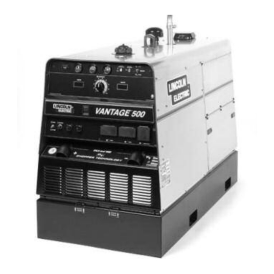
Lincoln Electric VANTAGE SVM178-B Service Manual (278 pages)
Lincoln Electric Welding System User Manual
Brand:
Lincoln Electric
| Category:
Welding System
| Size: 13 MB
Table of Contents
- Installation Section
9
Service Manual
1
California Proposition 65 Warnings
2
Electric and Magnetic Fields
2
Electric Shock Can Kill
3
Fumes and Gases
3
Table of Contents
9
Technical Specifications
10
Installation
10
Input - Diesel Engine
10
Physical Dimensions
10
Safety Precautions
11
Location/Ventilation
11
Storing
11
Stacking
11
Angle of Operation
11
Lifting
12
High Altitude Operation
12
High Temperature Operation
12
Towing
12
Vehicle Mounting
12
Pre-Operation Engine Service
13
Oil
13
Fuel
13
Fuel Cap
13
Engine Cooling System
13
Battery Connection
13
Muffler Outlet Pipe
14
Spark Arrester
14
High Frequency Generators for TIG Applications
14
Electrical Connections
14
Remote Control
14
Welding Terminals
14
Welding Output Cables
15
Machine Grounding
15
Auxiliary Power Receptacles
15
Standby Power Connections
15
- Operation Section
17
VANTAGE® 500 Deutz F3L912 (Code 10995)
17
General Description
18
Recommended Applications
19
Design Features and Advantages
19
Operating Instructions
18
Safety Instructions
18
Operation
18
Controls and Settings
20
Engine Controls
20
Welding Controls
21
Auxiliary Power Controls
22
Engine Operation
23
Starting the Engine
23
Stopping the Engine
23
Break-In Period
23
Typical Fuel Consumption
23
Welder Operation
24
Stick Welding
24
Tig Torch
25
Wire Feed (Constant Voltage) Welding
26
Auxiliary Power Operation
26
Arc Gouging
26
Paralleling
26
Simultaneous Welding and Auxiliary Power Loads
26
Extension Cord Recommendations
27
- Accessories Section
29
Optional Field Installed Accessories
30
Plasma Cutting Option
30
High Frequency Generators for TIG Applications
31
TIG Welding Options
31
Wire Feeder Options
31
- Maintenance Section
33
Routine and Periodic Maintenance
34
Engine Maintenance
34
Change the Oil and Oil Filter
34
Fuel
35
Fuel Filters
36
Air Filter
38
Maintenance Instructions
39
Cooling System
40
Maintenance Required
41
Cooling Blower Belt
41
Safety Precautions
34
Battery Maintenance
42
Installing a New Battery
42
Welder/Generator Maintenance
43
Nameplates
43
- Installation Section
45
VANTAGE® 500 Deutz F4L2011 (Code 11180, 11415)
45
Input - Diesel Engine
46
Installation
46
Physical Dimensions
46
Location/Ventilation
47
Storing
47
Stacking
47
Angle of Operation
47
Lifting
48
High Altitude Operation
48
High Temperature Operation
48
Towing
48
Vehicle Mounting
48
Safety Precautions
47
Pre-Operation Engine Service
49
Oil
49
Fuel
49
Fuel Cap
49
Engine Cooling System
49
Battery Connection
49
Muffler Outlet Pipe
50
Spark Arrester
50
Electrical Connections
50
Remote Control
50
Welding Terminals
50
Welding Output Cables
51
Machine Grounding
51
Auxiliary Power Receptacles
51
Standby Power Connections
51
High Frequency Generators for TIG Applications
50
- Operation Section
53
General Description
54
Recommended Applications
55
Design Features and Advantages
55
Operating Instructions
54
Safety Instructions
54
Operation
54
Controls and Settings
56
Engine Controls
56
Oil Pressure Gauge
57
Engine Protection
57
Idler Switch
57
Welding Controls
58
Auxiliary Power Controls
58
Engine Operation
59
Starting the Engine
59
Stopping the Engine
59
Break-In Period
59
Typical Fuel Consumption
59
Welder Operation
60
Tig Torch
61
Wire Feed (Constant Voltage) Welding
62
Auxiliary Power Operation
62
Arc Gouging
62
Paralleling
62
Simultaneous Welding and Auxiliary Power Loads
62
Extension Cord Recommendations
63
Optional Field Installed Accessories
66
Plasma Cutting
66
Tig Options
67
Wire Feeder Options
67
- Maintenance Section
69
Routine and Periodic Maintenance
70
Engine Maintenance
70
Change the Oil and Oil Filter
70
Fuel
71
Fuel Filters
72
Air Filter
73
Maintenance Instructions
74
Cooling System
75
Safety Precautions
70
Welder/Generator Maintenance
76
Receptacles
76
Cable Connections
76
Battery Maintenance
77
Installing a New Battery
77
Charging the Battery
77
- Installation Section
79
VANTAGE® 500 Deutz D2011L4I (Code 11468)
79
Input - Diesel Engine
80
Installation
80
Physical Dimensions
80
Location/Ventilation
81
Storing
81
Stacking
81
Angle of Operation
81
Lifting
82
High Altitude Operation
82
High Temperature Operation
82
Towing
82
Vehicle Mounting
82
Safety Precautions
81
Pre-Operation Engine Service
83
Oil
83
Fuel
83
Fuel Cap
83
Engine Cooling System
83
Battery Connection
83
Muffler Outlet Pipe
84
Spark Arrester
84
Electrical Connections
84
Remote Control
84
Welding Terminals
84
Welding Output Cables
85
Machine Grounding
85
Auxiliary Power Receptacles
85
Standby Power Connections
85
High Frequency Generators for TIG Applications
84
- Operation Section
87
General Description
88
Recommended Applications
89
Design Features and Advantages
89
Operating Instructions
88
Safety Instructions
88
Operation
88
Controls and Settings
90
Engine Controls
90
Oil Pressure Gauge
91
Engine Protection
91
Idler Switch
91
Welding Controls
92
Auxiliary Power Controls
92
Engine Operation
93
Starting the Engine
93
Stopping the Engine
93
Break-In Period
93
Typical Fuel Consumption
93
Welder Operation
94
Tig Torch
95
Wire Feed (Constant Voltage) Welding
96
Auxiliary Power Operation
96
Arc Gouging
96
Paralleling
96
Simultaneous Welding and Auxiliary Power Loads
96
Extension Cord Recommendations
97
Optional Field Installed Accessories
100
Plasma Cutting
100
Tig Options
101
Wire Feeder Options
101
- Maintenance Section
103
Safety Precautions
104
Engine Maintenance
104
Fuel
105
Fuel Filters
106
Air Filter
107
Maintenance Instructions
108
Cooling System
109
Cable Connections
110
Welder/Generator Maintenance
110
Receptacles
110
Battery Maintenance
111
Charging the Battery
111
- Installation Section
113
VANTAGE® 500 Cummins B3.3 (Code 10996)
113
Input - Diesel Engine
114
Installation
114
Physical Dimensions
114
Location/Ventilation
115
Storing
115
Stacking
115
Angle of Operation
115
Lifting
116
High Altitude Operation
116
High Temperature Operation
116
Towing
116
Vehicle Mounting
116
Safety Precautions
115
Pre-Operation Engine Service
117
Oil
117
Fuel
117
Fuel Cap
117
Engine Cooling System
117
Battery Connection
117
Muffler Outlet Pipe
118
Spark Arrester
118
Electrical Connections
118
Remote Control
118
Welding Terminals
118
Welding Output Cables
119
Machine Grounding
119
Auxiliary Power Receptacles
119
Standby Power Connections
119
High Frequency Generators for TIG Applications
118
- Operation Section
121
General Description
122
Recommended Applications
123
Design Features and Advantages
123
Operating Instructions
122
Safety Instructions
122
Operation
122
Controls and Settings
124
Engine Controls
124
Oil Pressure Gauge
125
Engine Protection
125
Idler Switch
125
Welding Controls
126
Auxiliary Power Controls
126
Engine Operation
127
Starting the Engine
127
Stopping the Engine
127
Typical Fuel Consumption
127
Welder Operation
128
Tig Torch
129
Wire Feed (Constant Voltage) Welding
130
Auxiliary Power Operation
130
Arc Gouging
130
Paralleling
130
Extension Cord Recommendations
131
Optional Field Installed Accessories
134
Plasma Cutting
134
Tig Options
135
Wire Feeder Options
135
- Maintenance Section
137
Safety Precautions
138
Engine Maintenance
138
Fuel
139
Cooling System
139
Drive Belt
139
Fuel Filters
140
Air Filter
141
Maintenance Instructions
142
Welder/Generator Maintenance
143
Receptacles
143
Cable Connections
143
Battery Maintenance
144
Charging the Battery
144
- Installation Section
147
VANTAGE® 500 Cummins B3.3 (Code 11181, 11416)
147
Installation
148
Location/Ventilation
149
Storing
149
Stacking
149
Angle of Operation
149
Lifting
150
High Altitude Operation
150
High Temperature Operation
150
Towing
150
Vehicle Mounting
150
Pre-Operation Engine Service
151
Oil
151
Fuel
151
Fuel Cap
151
Engine Cooling System
151
Battery Connection
151
Muffler Outlet Pipe
152
Spark Arrester
152
Electrical Connections
152
Remote Control
152
Welding Terminals
152
Welding Output Cables
153
Machine Grounding
153
Auxiliary Power Receptacles
153
Standby Power Connections
153
High Frequency Generators for TIG Applications
152
- Operation Section
155
General Description
156
Recommended Applications
157
Design Features and Advantages
157
Operating Instructions
156
Safety Instructions
156
Operation
156
Controls and Settings
158
Engine Controls
158
Welding Controls
160
Auxiliary Power Controls
160
Engine Operation
161
Starting the Engine
161
Stopping the Engine
161
Typical Fuel Consumption
161
Welder Operation
162
Wire Feed (Constant Voltage) Welding
164
Auxiliary Power Operation
164
Arc Gouging
164
Paralleling
164
Simultaneous Welding and Auxiliary Power Loads
165
- Maintenance Section
171
Maintenance
172
Safety Precautions
172
Cooling System
173
Drive Belt
173
Fuel Filters
174
Air Filter
175
Welder/Generator Maintenance
177
Storage
177
Cleaning
177
Nameplates
177
Brush Removal and Replacement
177
Bearings
177
Receptacles
177
Cable Connections
177
Battery Maintenance
178
Cleaning the Battery
178
Checking Specific Gravity
178
Checking Electrolyte Level
178
Charging the Battery
178
Theory of Operation
182
Weld Control Board
184
Insulated Gate Bipolar Transistor (Igbt) Operation
185
Pulse Width Modulation
186
Minimum Output
186
Maximum Output
186
Chopper Technology Fundamentals
187
- Troubleshooting and Repair
189
How to Use Troubleshooting Guide
190
PC Board Troubleshooting Procedures
191
Electric Shock
191
Troubleshooting and Repair
197
Troubleshooting and Repair
191
Case Cover Removal and Replacement Procedure
201
Test Description
201
Materials Needed
201
Chopper Module Capacitor Discharge Procedure
203
Chopper Module Resistance Test Procedure
205
Test Procedure
210
Shutdown Solenoid Test
212
Engine Throttle Adjustment Test
213
Left Side
215
Rotor Resistance Test
217
Flashing and Rotor Voltage Test
219
Stator Voltage Test
221
Stator Voltage Test
224
Output Rectifier Bridge Test
225
Diode Test
229
Test Instrument
229
Electronic Governor Test
231
Charging Circuit Test
233
Normal Open Circuit Voltage Waveform (115VAC Supply
235
Scope Settings
235
Normal Open Circuit Voltage Waveform (Stick)
236
Normal Weld Voltage Waveform (Stick CC)
237
Normal TIG Mode Voltage Waveform
238
Normal Weld Voltage Waveform (Wire CV)
240
Shutdown Solenoid Removal and Replacement
241
Stator/Rotor Removal and Replacement
247
Filter Capacitor
249
Flex Plate
254
Reassembly Notes
254
Retest after Repair
256
Engine Rpm
256
Troubleshooting and Repair
257
Auxiliary Power Output
257
Electrical Diagrams
260
Electrical Diagrams
263
Schematic - Complete Machine (G4363 Code 10995 Deutz)
264
Schematic - Complete Machine (G4442 Code 10996 Cummins)
266
Schematic - Complete Machine (G4848 Codes 11180, 11415 &11468 Deutz)
268
Schematic - Weld Control PC Board* (G4108-1)
271
Schematic - Chopper PC Board* (M19792-1
276
Advertisement
Advertisement
Related Products
Lincoln Electric POWER MIG SVM170-A
Lincoln Electric POWER FEED 10M SINGLE/DUAL SVM172-A
Lincoln Electric POWER WAVE SVM173-A
Lincoln Electric SVM188-A
Lincoln Electric SVM143-A
Lincoln Electric INVERTEC SVM199-A
Lincoln Electric LN-15 WIRE FEEDER SVM166-A
Lincoln Electric PRECISION TIG SVM186-A
Lincoln Electric SHIELD-ARC SVM128-A
Lincoln Electric SEVERE DUTY SVM187-A
Lincoln Electric Categories
Welding System
Welding Accessories
Flashlight
Wire Feeders
Portable Generator
More Lincoln Electric Manuals
Login
Sign In
OR
Sign in with Facebook
Sign in with Google
Upload manual
Upload from disk
Upload from URL