Table of Contents
Advertisement
POWER-ARC
For Machines with code Number 10083 Refer to SVM103-A (on Service Navigator CD)
Safety Depends on You
Lincoln arc welding and cutting
equipment is designed and built
with safety in mind. However, your
overall safety can be increased by
proper installation ... and thought-
ful operation on your part. DO
NOT INSTALL, OPERATE OR
REPAIR THIS EQUIPMENT
WITHOUT
READING
MANUAL AND THE SAFETY
PRECAUTIONS CONTAINED
THROUGHOUT. And, most
importantly, think before you act
and be careful.
• Sales and Service through Subsidiaries and Distributors Worldwide •
Cleveland, Ohio 44117-1199 U.S.A. TEL: 216.481.8100 FAX: 216.486.1751 WEB SITE: www.lincolnelectric.com
RETURN TO MAIN INDEX
For Machines with Code Numbers: 10200
THIS
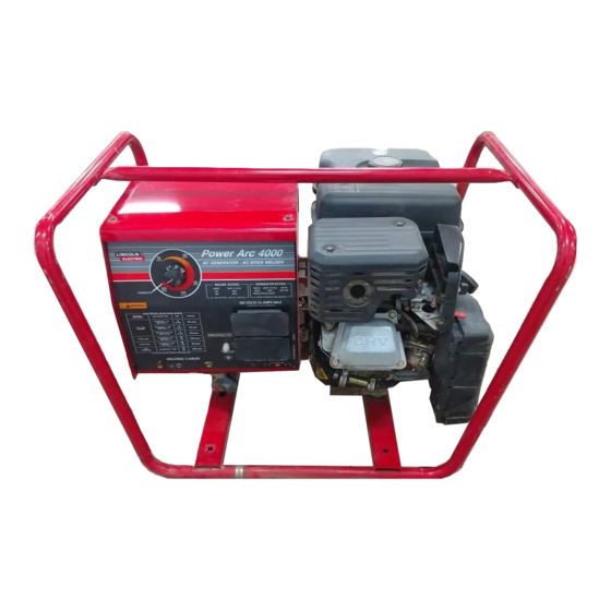
Various engine configurations are available and machine appearance
will vary accordingly.
SERVICE MANUAL
• World's Leader in Welding and Cutting Products •
™
4000
10585
10673
10202
10667
10792
10243
10671
10793
10244
10672
10866
Copyright © 2002 Lincoln Global Inc.
SVM103-C
April, 2002
Advertisement
Chapters
Table of Contents
Troubleshooting

Related Manuals for Lincoln Electric POWER-ARC SVM103-C


Summary of Contents for Lincoln Electric POWER-ARC SVM103-C
-
Page 1: Service Manual
POWER-ARC For Machines with Code Numbers: 10200 For Machines with code Number 10083 Refer to SVM103-A (on Service Navigator CD) Safety Depends on You Lincoln arc welding and cutting equipment is designed and built with safety in mind. However, your overall safety can be increased by proper installation ... -
Page 2: Safety
351040, Miami, Florida 33135 or CSA Standard W117.2-1974. A Free copy of “Arc Welding Safety” booklet E205 is available from the Lincoln Electric Company, 22801 St. Clair Avenue, Cleveland, Ohio 44117-1199. BE SURE THAT ALL INSTALLATION, OPERATION, MAINTENANCE AND REPAIR PROCEDURES ARE PERFORMED ONLY BY QUALIFIED INDIVIDUALS. -
Page 3: Electric Shock Can Kill
ELECTRIC SHOCK can kill. 3.a. The electrode and work (or ground) circuits are electrically “hot” when the welder is on. Do not touch these “hot” parts with your bare skin or wet clothing. Wear dry, hole-free gloves to insulate hands. - Page 4 WELDING SPARKS can cause fire or explosion. 6.a. Remove fire hazards from the welding area. If this is not possible, cover them to prevent the welding sparks from starting a fire. Remember that welding sparks and hot materials from welding can easily go through small cracks and openings to adjacent areas.
- Page 5 PRÉCAUTIONS DE SÛRETÉ Pour votre propre protection lire et observer toutes les instruc- tions et les précautions de sûreté specifiques qui parraissent dans ce manuel aussi bien que les précautions de sûreté générales suivantes: Sûreté Pour Soudage A L’Arc 1. Protegez-vous contre la secousse électrique: a.
-
Page 6: Table Of Contents
MASTER TABLE OF CONTENTS FOR ALL SECTIONS Safety...i-iv Installation ...Section A Technical Specifications ...A-2 Safety Precautions...A-3 Location and Ventilation ...A-3 Pre-operation Engine Service ...A-4 Electrical Output Connections ...A-6 Operation...Section B Safety Instructions ...B-2 General Description ...B-2 Recommended Applications...B-3 Operational Features and Controls...B-3 Design Features and Advantages...B-3 Welding Capability ...B-3 Limitations ...B-3... -
Page 7: Installation Section
Section A - INSTALLATION SECTION - Installation ...Section A Technical Specifications ...A-2 Safety Precautions...A-3 Location and Ventilation ...A-3 Storing ...A-3 Stacking...A-4 Tilting ...A-4 Lifting ...A-4 Pre-operation Engine Service ...A-4 ...A-4 Fuel ...A-4 Muffler Defelector ...A-4 Spark Arrester...A-5 Electrical Output Connections ...A-6 Welding Cable Connections ...A-6 Cable Size and Length ...A-6 Cable Installation...A-7... -
Page 8: Installation
4 cycle air-cooled OHV gasoline 9 HP @ 3750 RPM RATED OUTPUT - WELDER Duty Cycle 30% Duty Cycle 60% Duty Cycle OUTPUT - WELDER AND GENERATOR Welding Ranges 70 - 125 Amps Height 20.9 in. 530 mm INSTALLATION Speed Displacement 3700 RPM 19.4 cu. -
Page 9: Safety Precautions
Read this entire installation section before you start installation. SAFETY PRECAUTIONS WARNING Do not attempt to use this equipment until you have thoroughly read all the operation and maintenance manuals supplied with your machine. They include important safety precautions; detailed engine starting, operating, and maintenance instructions;... -
Page 10: Pre-Operation Engine Service
STACKING POWER-ARC 4000 machines CANNOT be stacked. TILTING Place the machine on a secure, level surface whenev- er you use it or store it. Any surfaces you place it on other than the ground must be firm, non-skid, and structurally sound. The gasoline engine is designed to run in a level posi- tion for best performance. -
Page 11: Spark Arrester
Power-Arc 4000 Typical Fuel Consumption B&S 8 HP Carb. Certified Intek .28 Gallons/Hour No Load 3700 RPM + 50 R.P.M. (1.06 Liters/Hour) .57 Gallons/Hour AC CC Weld Output (2.16 Liters/Hour) 125 Amps @ 18 Volts AC CC Weld Output .52 Gallons/Hour (1.97 Liters/Hour) 100 Amps @25 Volts .59 Gallons/Hour... -
Page 12: Electrical Output Connections
Table A.1 lists recommended cable sizes and lengths for rated current and duty cycle. Length refers to the distance from the welder to the work and back to the welder. Cable diameters are increased for long cable lengths to reduce voltage drops. -
Page 13: Cable Installation
• Do not cross the welding cables at the output termi- nal connection. Keep the cables isolated and sepa- rate from one another. Lincoln Electric offers a welding accessory kit with the properly specified welding cables. See the ACCESSORIES section of this manual for more infor- mation. -
Page 14: Premises Wiring
PREMISES WIRING The POWER-ARC 4000 three-wire, grounded neutral generator allows it to be connected to premises wiring. However, the wiring procedure needed to meet the National Electric Code (NEC) regulations as well as city ordinances can be confusing. The con- nections could vary from a “commonly grounded”... - Page 15 Capacitive/Inductive Computers, high resolution TV sets, complicated electrical equipment. The Lincoln Electric Company is not responsible for any damage to electrical components improperly connect- ed to the POWER-ARC 4000. INSTALLATION CAUTION TABLE A.2 POWER-ARC 4000...
- Page 16 A-10 A-10 NOTES POWER-ARC 4000...
-
Page 17: Design Features And Advantages
Welder ...B-3 Operational Features and Controls...B-3 Design Features and Advantages...B-3 Welding Capability ...B-3 Limitations ...B-3 Controls and Settings ...B-4 Generator/Welder Controls ...B-4 Gasoline Engine Controls...B-5 Engine Operation ...B-6 Before Starting the Engine ...B-6 Starting the Engine ...B-6 Stopping the Engine...B-7 Break-In Period ...B-7... -
Page 18: Safety Precautions
As a generator it can supply up to 4,000 continuous watts (or 4,400 surge watts) of 120/240 volt, single-phase AC power. As a welder it provides 125 amps of AC constant current for weld- ing with AC stick electrodes. A single dial provides continuous adjustment of welding output. -
Page 19: Recommended Applications
The POWER-ARC 4000 is rated 125 amps, 20 volts at 30% duty cycle on a ten-minute basis. This means that you can load the welder to 125 amps for three minutes out of every ten-minute period. The machine is also capable of higher duty cycles at lower output currents. -
Page 20: Controls And Settings
CONTROLS AND SETTINGS All generator/welder controls are located on the Output Control Panel. Gasoline engine controls are mounted on the engine. See Figures B.1 and B.2 and the explanations that follow. FIGURE B.1 – OUTPUT PANEL CONTROLS ELECTRODE SELECTION GUIDE 1. -
Page 21: Gasoline Engine Controls
5. GROUND STUD: Provides a connection point for connecting the machine case to earth ground for the safest grounding procedure. 6. 20 AMP CIRCUIT BREAKERS (2): Provide sepa- rate overload current protection for the 120 volt and 240 volt receptacles. FIGURE B.2 –... -
Page 22: Engine Operation
7. RECOIL STARTER: Manual, rope-type starter. The handle position allows easy starting from either ground level or pickup-truck level. 8. OIL DRAIN PLUG: Permits convenient draining of engine oil during maintenance. Both sides of the engine are equipped with an oil drain plug. 9. -
Page 23: Stopping The Engine
4. Pull the cord rapidly. 5. If the engine does not start, open the choke slightly (move lever upward) and pull the starter cord rapidly again. When the engine starts, gradually open the choke to the “RUN” position. To open the choke fully, requires an engine warm-up period of several seconds to several minutes depending on the temprature. -
Page 24: Generator Operation
GENERATOR OPERATION CAUTION Be sure that any electrical equipment plugged into the generator’s AC power receptacles can with- stand a ±10% voltage and a ±5% frequency varia- tion. Some electronic devices cannot be powered by the POWER-ARC 4000. Refer to Table A.2, ELECTRICAL DEVICE USE WITH THE POWER- ARC 4000, in the INSTALLATION section of this manual. - Page 25 *Submersible Pump - 1 HP *Sump Pump Toaster Weed Trimmer Lincoln 100 or 125 Amp Wire Feeder/Welder NOTES: Wattages listed are approximate. Check your equipment for actual wattage. Equipment with unusually high *START-UP WATTS are listed. For start-up of other equipment listed in the table, multiply RUNNING WATTS by 2.
-
Page 26: Welding Operation
100 Amps. 2. Duty cycle is based on a ten minute period. The welder can be loaded to 125 Amps for three minutes out of every ten minute period or to 100 Amps for six minutes out of every ten minute period. -
Page 27: Learning To Stick Weld
The Power-Arc generator power can be used to supply power to a Lincoln Weld-Pak 100 or Weld-Pak 125 wire feed welder. The Weld-Pak is equipped with all the supplies needed for Flux-Cored Arc Welding (FCAW), and is available where Lincoln products are sold. - Page 28 Many variables beyond the control of The Lincoln Electric Company affect the results obtained in applying this type of information. These variables include, but are not limit-...
- Page 29 The electric arc is made between the work and the tip end of a small metal wire, the electrode, which is clamped in a holder that is held by the welder. A gap is made in the welding circuit by holding the tip of the electrode 1/16 - 1/8”...
- Page 30 B-14 1. The Correct Welding Position Illustrated is the correct welding position for right-handed people. (For left-handed people it is opposite.) Whenever possible, weld from left to right (if right- handed). This enables you to see clearly what you are doing. Hold the electrode at a slight angle as shown in Figure 5.
- Page 31 B-15 PRACTICE The best way of getting practice in the four skills that enable you to maintain: 1. Correct Welding Position. 2. Correct Way to Strike An Arc. 3. Correct Arc Length. 4. Correct Welding Speed. is to spend a little more time on the following exer- cise.
- Page 32 B-16 Now weld the two plates together. Weld from left to right (if right-handed). Point the electrode down in he gap between the two plates, keeping the electrodes slightly tilted in the direction of travel. 90° end view Watch the molten metal to be sure it distributes itself evenly on both edges and in between the plates.
- Page 33 B-17 Vertical-Up Welding The problem, when welding vertical-up, is to put the molten metal where it is wanted and make it stay there. If too much molten metal is deposited, gravity will pull it downwards and make it “drip”. Therefore, a certain technique has to be followed: Long arc Short arc...
- Page 34 Various techniques are used for overhead welding. However, in the interest of simplicity for the inexperi- enced welder, the following technique will probably take care of his needs for overhead welding: 1. Use 1/8” (3.2mm) 90-105 A or 3/32” (2.5mm) 70 A AWS 6011 electrode on AC.
- Page 35 B-19 4. The bead should be put on with a weaving motion, and it should be 1/2-3/4” (12.7-19.0mm) wide. Do not let the arc blow over the edge, as that will dull the edge. (See drawing below.) Strike Arc Work Table Here Brick Plow Share...
- Page 36 B-20 strip may be used and plates may be gapped 1/8” (3.2mm) or more, as shown in figure (b). Scrap steel back-up strip Three ways to prepare plates where complete penetration is necessary. On sections where only a sealed joint is required and strength is not important, the joint may be welded after slightly veeing out the seam as shown in figure (d) below.
-
Page 37: Accessories Section
Section C - ACCESSORIES SECTION - Accessories...Section C Lincoln Electric Accessories ...C-2 Accessory Set (K875) ...C-2 Power Plug Kit (K802T) ...C-2 GFCI Receptacle Kit (K896-3) ...C-2 Undercarriage (K882-2) ...C-2 Rotor Removal Kit ...C-2 Briggs and Stratton Accessories ...C-2 Foam Pre-Cleaner ...C-2 Oil Gard ®... -
Page 38: Accessories
In addition to using the accessories/options listed above, the POWER-ARC 4000 generator can supply power to a Lincoln ELectric Weld-Pak 100 or Weld- Pak 125 wire feed welder. The Weld-Pak comes with all the supplies needed for Flux-Cored Arc Welding (FCAW). -
Page 39: Routine And Periodic Maintenance
Engine Adjustments ...D-2 Clean Engine ...D-3 Clean Cooling System...D-3 Spark Plug...D-3 Clean Spark Arrestor Screen ...D-3 Engine Maintenance Schedule...D-4 Engine Maintenance Parts ...D-4 Generator/Welder Maintenance ...D-5 Storage...D-5 Cleaning ...D-5 Brush Removal and Replacement...D-5 Receptacles ...D-5 Cable Connections...D-5 Major Component Locations ...D-6... -
Page 40: Maintenance
SAFETY PRECAUTIONS WARNING • Have qualified personnel do all maintenance and troubleshooting work. • Turn the engine off before working inside the machine. • Remove guards only when necessary to per- form maintenance and replace them when the maintenance requiring their removal is com- plete. -
Page 41: Clean Engine
CAUTION Do not use petroleum solvents such as kerosene to clean the air cleaner. They may cause deterio- ration of the air cleaner. DO NOT OIL THE AIR CLEANER OR USE PRESSURIZED AIR TO CLEAN OR DRY THE AIR CLEANER. To service the pre-cleaner: 1. -
Page 42: Clean Cooling System
Maintenance Operation Check Oil Level Change Oil Clean Rotating Screen, Finger Guard, or Debris Screen Service Foam Pre-Cleaner Service Air Cleaner (if no pre-cleaner) Service Air Cleaner (if pre-cleaner present) Clean Cooling System Inspect Spark Arrester (Option) Clean or Replace Spark Plug Replace In-Line Fuel Filter (Option) Remove Combustion Deposits Change oil after first 5 hours, then after every 50 hours or once a year. -
Page 43: Generator/Welder Maintenance
GENERATOR/WELDER MAINTENANCE STORAGE: Store the POWER-ARC 4000 in clean, dry, protected areas. CLEANING: Blow out the generator and controls periodically with low pressure air. Do this at least once a week in particularly dirty areas. BRUSH REMOVAL AND REPLACEMENT: See Figure D.5. - Page 44 MAINTENANCE FIGURE D.6. - MAJOR COMPONENT LOCATIONS 1 . CRADLE ASSEMBLY 2. ROTOR, BLOWER, AND BEARING ASSEMBLY 3. STATOR ASSEMBLY 4. BRUSH AND BRUSH HOLDER ASSEMBLY 5. CONTROL BOX WELDED ASSEMBLY 6. REACTOR ASSEMBLY 7. OUTPUT TERMINAL ASSEMBLY 8. OUTPUT PANEL ASSEMBLY POWER-ARC 4000...
-
Page 45: Theory Of Operation Section
Section E - THEORY OF OPERATION SECTION - Theory of Operation...Section E Power Supply Operation...E-1 - E-4 Engine, Excitation, Rotor and Stator...E-2 Rotor Field Feedback and Auxiliary Power ...E-3 Weld Winding and Reactor ...E-4 Auxiliary Power Overcurrent Protection ...E-4 ENGINE MECHANICAL ROTATION MAGNETO... -
Page 46: Theory Of Operation
THEORY OF OPERATION FIGURE E.2 – ENGINE, ROTOR AND STATOR ENGINE MECHANICAL ROTATION MAGNETO RHEOSTAT ENGINE, EXCITATION, ROTOR AND STATOR A small voltage developed by the engine magneto is fed through a diode to the rotating field coil in the rotor via a brush and slip ring configuration. - Page 47 THEORY OF OPERATION FIGURE E.3 – FIELD EXCITATION AND AUXILIARY POWER ENGINE MECHANICAL ROTATION MAGNETO RHEOSTAT ROTOR FIELD FEEDBACK AND AUXILIARY POWER The AC voltage developed in the field winding is fed to the full wave bridge. The DC output of the bridge is filtered by the field capacitor and controlled by the output rheostat.
- Page 48 THEORY OF OPERATION ENGINE MECHANICAL ROTATION MAGNETO RHEOSTAT WELD WINDING AND REACTOR The AC voltage developed in the stator weld winding is delivered, through the reactor, to the machine out- put terminals. The PowerArc 4000 provides the user with 125 amps of constant current AC welding for stick electrodes.
- Page 49 Section F - TROUBLESHOOTING & REPAIR SECTION - Troubleshooting & Repair Section ...Section F How to Use Troubleshooting Guide ...F-2 Troubleshooting Guide...F2 - F-10 Test Procedures Rotor Voltage Test...F-11 Rotor Resistance Test ...F-13 Engine Throttle Adjustment Test ...F-16 Oscilloscope Waveforms Normal Open Circuit Weld Voltage Waveform ...F-19 Normal Open Circuit Weld Voltage Waveform (115 VAC Supply)...F-20 Typical Weld Output Waveform - Machine Loaded ...F-21...
-
Page 50: Troubleshooting And Repair
TROUBLESHOOTING & REPAIR HOW TO USE TROUBLESHOOTING GUIDE Service and repair should be performed by only Lincoln Electric Factory Trained Personnel. Unauthorized repairs performed on this equipment may result in danger to the technician and machine operator and will invalidate your factory warranty. For your safety and to avoid Electrical Shock, please observe all safety notes and precautions detailed throughout this manual. -
Page 51: Troubleshooting
If for any reason you do not understand the test procedures or are unable to perform the tests/repairs safely, contact the Lincoln Electric Service Department for technical troubleshooting assistance before you proceed. Call 1-800-833-9353 TROUBLESHOOTING POSSIBLE AREAS OF... -
Page 52: Troubleshooting
- engine runs normally. If for any reason you do not understand the test procedures or are unable to perform the tests/repairs safely, contact the Lincoln Electric Service Department for technical troubleshooting assistance before you proceed. Call 1-800-833-9353 TROUBLESHOOTING... - Page 53 If for any reason you do not understand the test procedures or are unable to perform the tests/repairs safely, contact the Lincoln Electric Service Department for technical troubleshooting assistance before you proceed. Call 1-800-833-9353 TROUBLESHOOTING POSSIBLE AREAS OF...
- Page 54 - engine runs normally. If for any reason you do not understand the test procedures or are unable to perform the tests/repairs safely, contact the Lincoln Electric Service Department for technical troubleshooting assistance before you proceed. Call 1-800-833-9353 TROUBLESHOOTING...
- Page 55 Low weld output and low auxiliary output. If for any reason you do not understand the test procedures or are unable to perform the tests/repairs safely, contact the Lincoln Electric Service Department for technical troubleshooting assistance before you proceed. Call 1-800-833-9353 TROUBLESHOOTING POSSIBLE AREAS OF...
- Page 56 Engine will not start. If for any reason you do not understand the test procedures or are unable to perform the tests/repairs safely, contact the Lincoln Electric Service Department for technical troubleshooting assistance before you proceed. Call 1-800-833-9353 TROUBLESHOOTING POSSIBLE AREAS OF...
- Page 57 Engine sputters but will not start. If for any reason you do not understand the test procedures or are unable to perform the tests/repairs safely, contact the Lincoln Electric Service Department for technical troubleshooting assistance before you proceed. Call 1-800-833-9353 TROUBLESHOOTING...
- Page 58 If for any reason you do not understand the test procedures or are unable to perform the tests/repairs safely, contact the Lincoln Electric Service Department for technical troubleshooting assistance before you proceed. Call 1-800-833-9353 TROUBLESHOOTING POSSIBLE AREAS OF...
-
Page 59: Test Description
F-11 TROUBLESHOOTING & REPAIR Service and repair should be performed by only Lincoln Electric factory trained personnel. Unauthorized repairs performed on this equipment may result in danger to the technician or machine operator and will invalidate your factory warranty. For your safety and to avoid electrical shock, please observe all safety notes and precautions detailed throughout this manual. -
Page 60: Ground Stud
F-12 TROUBLESHOOTING & REPAIR ROTOR VOLTAGE TEST (continued) FIGURE F.1 - LOCATION OF LEAD 200A FOR ROTOR VOLTAGE TEST LEAD 200 CONNECTION TEST PROCEDURE 1. With the 5/16” nut driver, remove the 4 sheet metal screws that hold the top cover to the control box. Remove the top cover. -
Page 61: Rotor Resistance Test
TROUBLESHOOTING & REPAIR ROTOR RESISTANCE TEST Service and repair should be performed by only Lincoln Electric factory trained personnel. Unauthorized repairs performed on this equipment may result in danger to the technician or machine operator and will invalidate your factory warranty. For your safety and to avoid electrical shock, please observe all safety notes and precautions detailed throughout this manual. - Page 62 F-14 TROUBLESHOOTING & REPAIR ROTOR RESISTANCE TEST (continued) LOCATION OF ROTOR SLIP RINGS - BRUSH HOLDER ASSEMBLY REMOVED SLIP RINGS TEST PROCEDURE 1. Conduct the test with the gasoline engine OFF. 2. Remove the spark plug wire to pre- vent accidental engine kickback or starting.
- Page 63 F-15 TROUBLESHOOTING & REPAIR ROTOR RESISTANCE TEST (continued) FIGURE F.3 - BRUSHES RETAINED WITH CABLE TIE CABLE BRUSHES 9. Reinstall the brush holder assembly after the test. Depress the spring- loaded brushes into the holder and slip a suitable non-metallic, fairly stiff retainer through the slots at the top and bottom of the holder.
-
Page 64: Engine Throttle Adjustment Test
TROUBLESHOOTING & REPAIR ENGINE THROTTLE ADJUSTMENT TEST Service and repair should be performed by only Lincoln Electric factory trained personnel. Unauthorized repairs performed on this equipment may result in danger to the technician or machine operator and will invalidate your factory warranty. - Page 65 F-17 TROUBLESHOOTING & REPAIR ENGINE THROTTLE ADJUSTMENT TEST (continued) FIGURE F.4 - BLOWER PADDLE MARKED FOR STROBE-TACH METHOD MARK TEST PROCEDURE This test can be conducted by any of three methods. Strobe-tach Method: 1. Stop the engine and remove the spark plug wire to prevent acciden- tal kickback or starting.
- Page 66 F-18 TROUBLESHOOTING & REPAIR ENGINE THROTTLE ADJUSTMENT TEST (continued) FIGURE F.5 - LOCATION OF ENGINE THROTTLE ADJUSTMENT NUT 2. Loosen Wing Nut (Refer to Figure F.5) 3. Refering to Figure F.5, adjust high speed stop screw to adjust the waveform period to 15.8 millisec- onds.
-
Page 67: Normal Open Circuit Weld Voltage Waveform
F-19 TROUBLESHOOTING & REPAIR NORMAL OPEN CIRCUIT WELD VOLTAGE WAVEFORM HIGH IDLE – NO LOAD 5 ms 50 volts This is the typical AC output voltage generated from a properly operating machine. Note that each vertical divi- sion represents 50 volts and that each horizontal division represents 5 milliseconds in time. -
Page 68: Normal Open Circuit Weld Voltage Waveform (115 Vac Supply
F-20 TROUBLESHOOTING & REPAIR NORMAL OPEN CIRCUIT VOLTAGE WAVEFORM (115 VAC SUPPLY) 1 Period = 16.2 ms @ 3700 rpm HIGH IDLE – NO LOAD 5 ms 20 volts This is the typical AC output voltage generated from a properly operating machine. -
Page 69: Typical Weld Output Waveform - Machine Loaded
F-21 TROUBLESHOOTING & REPAIR TYPICAL WELD OUTPUT WAVEFORM MACHINE LOADED TO 125 AMPS AT 23 VAC MACHINE LOADED 5 ms 20 volts This is the typical AC output voltage generated from a properly operating machine. Note that each vertical divi- sion represents 20 volts and that each horizontal division represents 5 milliseconds in time. -
Page 70: Brush Removal And Replacement
TROUBLESHOOTING & REPAIR BRUSH REMOVAL AND REPLACEMENT Service and repair should be performed by only Lincoln Electric factory trained personnel. Unauthorized repairs performed on this equipment may result in danger to the technician or machine operator and will invalidate your factory warranty. - Page 71 F-23 TROUBLESHOOTING & REPAIR BRUSH REMOVAL AND REPLACEMENT (continued) FIGURE F.6 - BRUSHES RETAINED WITH CABLE TIE CABLE BRUSHES PROCEDURE 1. Remove the spark plug wire. 2. Open the brush holder assembly cover. Squeeze the 2 tabs and depress the cover at the top with a screw driver or your fingernail.
- Page 72 F-24 TROUBLESHOOTING & REPAIR BRUSH REMOVAL AND REPLACEMENT (continued) PROCEDURE 8. To reinstall the brush holder assembly, depress the spring- loaded brushes into the holder and slip a suitable non-metallic, fairly stiff retainer through the slots at the top and bottom of the holder. A cable tie works well;...
-
Page 73: Rheostat Removal And Replacement
TROUBLESHOOTING & REPAIR RHEOSTAT REMOVAL AND REPLACEMENT Service and repair should be performed by only Lincoln Electric factory trained personnel. Unauthorized repairs performed on this equipment may result in danger to the technician or machine operator and will invalidate your factory warranty. - Page 74 F-26 TROUBLESHOOTING & REPAIR RHEOSTAT REMOVAL AND REPLACEMENT See Figure F.7 for steps 3 - 9. PROCEDURE 1. Remove the spark plug wire. 2. With the 5/16” nut driver, remove the 4 sheet metal screws that hold the top cover to the control box. Remove the top cover.
-
Page 75: Capacitor And Diode Bridge Removal And Replacement
CAPACITOR AND/OR DIODE BRIDGE REMOVAL AND REPLACEMENT Service and repair should be performed by only Lincoln Electric factory trained personnel. Unauthorized repairs performed on this equipment may result in danger to the technician or machine operator and will invalidate your factory warranty. - Page 76 F-28 TROUBLESHOOTING & REPAIR CAPACITOR AND/OR DIODE BRIDGE REMOVAL AND REPLACEMENT FIGURE F.8 - LOCATION AND DISCHARGING THE FIELD CAPACITOR Attachment for 202A Cable Tie PROCEDURE - CAPACITOR REMOVAL AND REPLACE- MENT 1. Remove the engine spark plug wire. 2. With the 5/16” nut driver, remove the sheet metal screws that hold the top cover to the control box.
- Page 77 F-29 TROUBLESHOOTING & REPAIR CAPACITOR AND/OR DIODE BRIDGE REMOVAL AND REPLACEMENT FIGURE F.8A - FIELD DIODE BRIDGE LOCATION 201 (Black) 201B (Black) – PROCEDURE - FIELD DIODE BRIDGE REMOVAL AND REPLACEMENT 1. Remove the engine spark plug wire. 2. With the 5/16” nut driver, remove the sheet metal screws that hold the top cover to the control box.
-
Page 78: Stator/Rotor Removal And Replacement (Kit S20925
TROUBLESHOOTING & REPAIR STATOR/ROTOR REMOVAL AND REPLACEMENT Service and repair should be performed by only Lincoln Electric factory trained personnel. Unauthorized repairs performed on this equipment may result in danger to the technician or machine operator and will invalidate your factory warranty. -
Page 79: Output Terminals
F-31 TROUBLESHOOTING & REPAIR STATOR/ROTOR REMOVAL AND REPLACEMENT (continued) STATOR REMOVAL PROCEDURE Remove engine spark plug wire to prevent accidental kickback or starting. With the 5/16” nut driver, remove the 4 sheet metal screws that hold the top cover to the control box. Remove the top cover. Remove the 4 1/2”... - Page 80 F-32 TROUBLESHOOTING & REPAIR STATOR/ROTOR REMOVAL AND REPLACEMENT (continued) 12. Slide a short length of 2 X 4 under the engine to support it when the stator is removed. 13. With the 1/2” socket wrench, remove the 2 nuts that hold the stator end bracket support.
-
Page 81: Reassembly Procedure
Pull out the thru-bolt. 3. Install the long thru-bolt supplied with Lincoln Electric Rotor Removal Kit S20925. The slot head must face out. Screw in the bolt with the slot head screw driver until the bolt bottoms out on the engine crank- shaft, about 3/4”. -
Page 82: Feeler Gauge
F-34 TROUBLESHOOTING & REPAIR STATOR/ROTOR REMOVAL AND REPLACEMENT (continued) 6. Install the bottom two end bracket thru- bolts. Note: The flat washer goes on the top right hand thru-bolt for the green ground wire. 7. Tap the end bracket with the mallet as nec- essary to position it. -
Page 83: Retest After Repair
Current Control Dial set at MAXIMUM or GENERATOR. Output values of each receptacle can vary within the range shown RETEST AFTER REPAIR ENGINE OUTPUT No Load RPM 3725 3675 WELDER/GENERATOR OUTPUT Field Amps Open Circuit Volts 4.8 - 5.8 60 - 63 –... - Page 84 NOTES...
- Page 85 Section G Section G TABLE OF CONTENTS - DIAGRAMS SECTION - Page DIAGRAMS SECTION ...Section G Wiring Diagram (S22160) ...G-2 Wiring Diagram (S22160-1) ...G-3 Wiring Diagram (S25341) ...G-4 Dimension Print...G-5 POWER-ARC 4000...
- Page 86 DIAGRAMS POWER-ARC 4000...
- Page 87 DIAGRAMS POWER-ARC 4000...
- Page 88 DIAGRAMS POWER-ARC 4000...
- Page 89 DIAGRAMS POWER-ARC 4000...
- Page 90 NOTES...
- Page 91 Your Company__________________________ Your Name_____________________________ Please give detailed description below: ___________________________________________________________________________ ___________________________________________________________________________ ___________________________________________________________________________ ___________________________________________________________________________ ___________________________________________________________________________ ___________________________________________________________________________ ___________________________________________________________________________ ___________________________________________________________________________ ___________________________________________________________________________ ___________________________________________________________________________ ___________________________________________________________________________ ___________________________________________________________________________ ___________________________________________________________________________ SD287 01/99 Thank You, Technical Services Group Lincoln Electric Co. 22801 ST. Clair Ave. Cleveland, Ohio 44117-1199 FAX 216-481-2309...
Need help?
Do you have a question about the POWER-ARC SVM103-C and is the answer not in the manual?
Questions and answers