Table of Contents
Advertisement
Advertisement
Table of Contents

Related Manuals for Simrad Halo


Summary of Contents for Simrad Halo
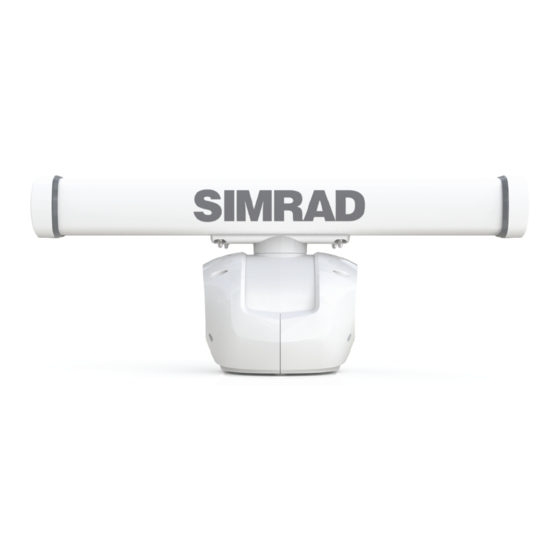
- Page 1 Halo® Pulse Compression Radar Installation Manual ENGLISH simrad-yachting.com...
- Page 3 This equipment is intended for use in international waters as well as coastal sea areas administered by countries of the E.U. and E.E.A. Compliance Statements The Simrad Halo® pulse compression radar, * Comply with CE under R&TTE directive 1999/5/EC. * The relevant Declaration of Conformity is available in the following website under model documentation section: www.simrad-yachting.com...
- Page 4 FRENCH: Le présent émetteur radio – Halo™ Pulse Compression Radar – (4697A-HALO) a été approuvé par Industrie Canada pour fonctionner avec les types d’antenne énumérés ci-dessous et ayant un gain admissible maximal et l’impédance requise pour chaque type d’antenne. Les types d’antenne non inclus dans cette liste, ou dont le gain est supérieur au gain maximal indiqué, sont strictement...
- Page 5 • NMEA 2000 is a registered trademark of the National Marine Electronics Association • Simrad is a trademark of Kongsberg Maritime AS Company registered in the US and other countries and is being used under license • B&G, Lowrance, StructureScan, Navico, SonicHub, SimNet, Skimmer, InsightHD, Halo Pulse...
- Page 6 Preface |Halo pulse compression radar installation manual...
-
Page 7: Table Of Contents
Sector blanking Adjust open array park angle Sidelobe suppression... Radar Status Reset Radar to factory defaults Control pedestal accent lighting Specifications Drawings RI-12 Pedestal and antennas Spare Parts Third party mounting options Contents | Halo pulse compression radar installation manual... -
Page 8: Introduction
¼ Note: Antennas are available in three sizes 3 ft, 4 ft and 6 ft to suit customer requirements. ¼ Note: At the time of release the Halo radar will only work with Simrad NSSevo2 and NSOevo2 systems ¼ Note: The radar should be installed by a qualified radar technician. -
Page 9: Check The Parts
Bolts, hex head , M12 x 50 mm, 316 s/s c) Flat washer, M12 x 36 x 3, 316 s/s d) Spring washer, M12, 316 s/s e) Isolating washer, M12 x 38 Drill template This manual Check the parts | Halo pulse compression radar installation manual... -
Page 10: Antenna
Mounting hard ware Ethernet adapter. RJ45 male to 5 pin female 150 mm (5.9”) Ethernet cable 1.8 m (6 ft) Micro-C T Joiner Micro-C drop cable 1.8 m (6 ft) 10 | Check the parts |Halo pulse compression radar installation manual... -
Page 11: Tools Required
Description Drill Torque wrench 19 mm socket 13 mm socket Drill bit 12.5 mm (1/2") Sharp Knife Screw driver (pozidrive) Screw driver (flat blade) Screw driver (flat blade, small) | 11 Tools required | Halo pulse compression radar installation manual... -
Page 12: Installation Guidelines
Warning: Before commencing any installation or maintenance on the Halo radar make sure the safety switch on the rear of the pedestal is set to OFF There is a transmit interlock that prevents radar transmissions if the scanner is not rotating. -
Page 13: Compass Safe Distance
3G / 4G Radar Do not install the Halo® pulse compression radar on the same beam plane as a conventional pulse radar. A pulse radar must be set to STBY or OFF any time the Halo® radar is being operated. ¼ Note: Possible interference could be reduced by using the sector blanking feature (see “”... -
Page 14: Considerations For Direct Roof Mounting
Considerations for direct roof mounting When deciding a suitable mounting location for the Halo® Pulse Compression Radar be aware that the vertical radar beam extends to 25° either side of horizontal. With 50% of the power projecting in a beam 12.5° off horizontal. If the radar beams cannot clear the roof line, this will decrease performance of the radar. -
Page 15: Hardware Mounting
RI-12 with machine screws nuts and washers. Use only 304 or 316 stainless steel fasteners. Mark the screw locations using RI-12 box as a template, and drill pilot holes. | 15 Hardware mounting | Halo pulse compression radar installation manual... -
Page 16: Install The Pedestal
RJ45 connector end to pass through to the RI-12 or 24 mm for the 14 pin connector to pass through to the pedestal.. Stick down the mounting template in the desired installation location, observing correct orientation. (Minor deviation can be compensated for in the radar software). 16 | Hardware mounting |Halo pulse compression radar installation manual... - Page 17 Drill pilot holes, Then use a 12.5 mm (1/2”) drill bit to drill the four holes where shown on the mounting template. Remove the mounting template . Lift the pedestal into position using the supplied lifting strap. Warning: Do not lift the pedestal with the antenna attached | 17 Hardware mounting | Halo pulse compression radar installation manual...
- Page 18 Connect the 14 pin end of the interconnection cable. Take care to align the connector correctly to avoid bending the pins. Secure the locking collar by rotating clockwise until it clicks. 18 | Hardware mounting |Halo pulse compression radar installation manual...
- Page 19 Place a flat washer and spring washer onto each bolt, as shown. Insert bolts into the drilled holes and locate into the pedestals threaded mounting holes and tighten securely. | 19 Hardware mounting | Halo pulse compression radar installation manual...
-
Page 20: Fitting The Antenna To The Pedestal
Tighten the dome nuts using socket and torque wrench to 15 N.m (11 ft·lbf) ¼ Note: A socket wrench is recommended to minimise risk of chipping the powder coated surface of the pedestal 20 | Hardware mounting |Halo pulse compression radar installation manual... -
Page 21: Wiring
Remove the grommet retaining clip Remove the rubber grommets Pass the cables through the rubber grommets and into the RI-12. Use a sharp knife to cut a slit the grommet. | 21 Wiring | Halo pulse compression radar installation manual... -
Page 22: Ri-12 Connections
DC input for the antenna park brake SCANNER RJ45: Ethernet data from the pedestal. Connect the RJ45 connector of the interconnection cable NETWORK/MFD RJ45: Connects the radar to the navigation Ethernet network 22 | Wiring |Halo pulse compression radar installation manual... -
Page 23: Led Indicator Lights
RJ45 (Interface module end) to pass through bulkheads or 24 mm hole for the 14 pin connector (pedestal end) to pass though. Run the interconnection cable between the pedestal and the location of the RI-12 Interface module. | 23 Wiring | Halo pulse compression radar installation manual... -
Page 24: Connect The Power Cable
The RI-12 has an optional remote power control mode that can enable a compatible multifunction display or ignition switch to control the power state of the radar (see “Remote power control” on page 27) 24 | Wiring |Halo pulse compression radar installation manual... - Page 25 Repeat this process to connect the negative wire to the negative power cable input connector (identified by the – sign) 12 or 24 V DC | 25 Wiring | Halo pulse compression radar installation manual...
-
Page 26: Grounding Requirements
It is recommended that the RI-12 ground is connected to the vessels bonded ground or a non bonded RF ground at the closest possible location, using 12 AWG wire (or thicker): 26 | Wiring |Halo pulse compression radar installation manual... -
Page 27: Remote Power Control
Description Halo® RI-12 Interface module NSO evo2 or other multifunction display (one or more multifunction display needs to be set to power control master) Other Simrad device with remote power control Power control bus DC Power | 27 Wiring |... -
Page 28: Network
An Ethernet network is used to distribute the radar data to compatible multi-function displays. The RI-12 is connected to the Ethernet network using a standard Simrad Ethernet cable and the supplied adapter cable. The RI-12 can be connected either directly to any Simrad compatible MFD or to a network switch such as an NEP-2 or SonarHub. -
Page 29: Nmea 2000
Halo® radar pedestal and antenna RI-12 interface modules NMEA 2000 compliant heading sensor Compatible multifunction display Micro-C drop cables Network power 12 V DC Micro-C backbone (NMEA 2000) with terminators | 29 Wiring | Halo pulse compression radar installation manual... -
Page 30: Nmea 0183
NMEA 2000 heading source. Antenna park The Halo® Pulse Compression Radar has the ability to stop rotating the antenna and hold it at a predetermined angle in relation to the ships heading line. The park angle is set in the display (see “Adjust open array park angle”... - Page 31 When all connections have been made and checked the safety switch on the rear of the pedestal can be set to the ON position | 31 Wiring | Halo pulse compression radar installation manual...
-
Page 32: Setup And Configuration
Setup and configuration Setup and configuration of the Halo® radar has been simplified compared to traditional pulse radars. There is no zero range adjustment (time delay), no warm up time, and no burn in required. Source On the radar page, choose the radar to be setup using the source drop down. MENU>SOURCE When setting up the Halo Pulse Compression radar choose either Halo-A or Halo-B ¼... -
Page 33: Adjust Bearing Alignment
Point the boat towards a stationary isolated object. Adjust the bearing alignment so the heading line touches the end of the same object. Use the slider control or the “+” or “-” buttons to set the value then SAVE | 33 Setup and configuration | Halo pulse compression radar installation manual... -
Page 34: Sector Blanking
By default this control is set to Auto, and normally should not need to be adjusted. However if there is significant metallic clutter around the radar, sidelobe suppression may need to be increased. The control should be adjusted as follows: 34 | Setup and configuration |Halo pulse compression radar installation manual... -
Page 35: Radar Status
Provides information on the radar such as Software version, Serial number, and operating hours Reset Radar to factory defaults Reset to factory defaults function will only reset radar control settings, not installation settings. | 35 Setup and configuration | Halo pulse compression radar installation manual... -
Page 36: Control Pedestal Accent Lighting
Control pedestal accent lighting The Halo™ Pulse Compression Radar pedestal has a blue accent light. The LED accent light has four light levels controlled from the radar menu. ¼ Note: The accent light can only be adjusted when the radar is in standby Halo™... -
Page 37: Specifications
Specifications Description 25 W Halo® Pulse Compression Radar System System consists of radar pedestal, antenna, Interconnection cable and RI-12 Interface Module. Type of emission FCC/IC/R&TTE Type Certification FCC ID: RAYHALO IC ID: 4697A-HALO R&TTE: Emissions compliant to SM1541-4 (including -40... - Page 38 10 m (33 ft), 20 m (66 ft), 30 m (100 ft) Ships with ( Max length 30 m (100 ft) 20 m (66 ft) Options for cable to exit from rear of pedestal or pole mount 38 | Specifications |Halo pulse compression radar installation manual...
-
Page 39: Drawings
Drawings RI-12 213.0 mm (8.39") 195.0 mm (7.68") | 39 Drawings | Halo pulse compression radar installation manual... -
Page 40: Pedestal And Antennas
Pedestal and antennas 427 mm (16.81") 292 mm (11.50") 135 mm (5.31") 262 mm (10.31") 40 | Drawings |Halo pulse compression radar installation manual... - Page 41 Antenna maximum rotation | 41 Drawings | Halo pulse compression radar installation manual...
-
Page 42: Spare Parts
7.7 m (25 ft) 000-0127-37 Ethernet cable 15.2 m (50 ft) 24005936 AT10 NMEA0183 / NMEA 2000 converter (SimNet connector) 24006694 AT10HD NMEA0183 heading to/ NMEA 2000 converter. (SimNet connector). 42 | Spare Parts |Halo pulse compression radar installation manual... -
Page 43: Third Party Mounting Options
ADA-R1 and a mounting tower RW4-7 4° Angled wedge adapter ADA-HALO-2 Adapter for replacing 3G/4G, Raymarine and Garmin radars with Halo PMA-DM2-M2 Dual mount. (Not for 6 ft Halo) | 43 Spare Parts | Halo pulse compression radar installation manual... - Page 44 150 mm (6”) Aluminium PowerTower® for Halo (3 ft, 4 ft, 6ft) DPT-40-SO3 Dual PowerTower® for 40 cm satcom plus Halo 3 ft or 4 ft DPT-60-SO3 Dual PowerTower® for 60 cm satcom plus Halo 3 ft or 4 ft 44 |...
- Page 46 0560...
Need help?
Do you have a question about the Halo and is the answer not in the manual?
Questions and answers