Table of Contents
Advertisement
Advertisement
Table of Contents

Related Manuals for Simrad TXL-10S-4


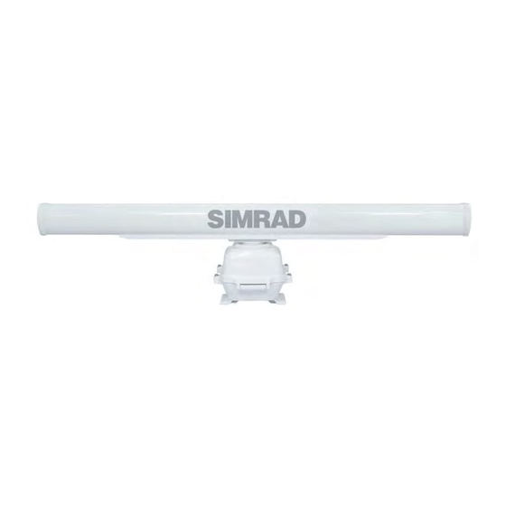
Summary of Contents for Simrad TXL-10S-4
- Page 1 10 kW and 25 kW Low Emission Radar Installation Manual ENGLISH...
- Page 2 E.U. and E.E.A. Compliance Statements The Simrad TXL-10S-4, TXL-10S-6, and TXL-25S-7: * Comply with CE under R&TTE directive 1999/5/EC. * Comply with the requirements of level 3 in Australia and level of conformity 3 in New Zealand.
- Page 3 System impedence Antenna part number/ antenna gain Transmitter description (dBi) Model (nominal) TXL-10S-4 768C-NKE2103 151-10359-001 - 4 foot antenna 27.9 dBi 50 ohm TXL-10S-6 768C-NKE2103 151-10360-001 - 6 foot antenna 29.9 dBi 50 ohm TXL-25S-7 768C-NKE2254 151-10361-001 - 7 foot antenna 30.7 dBi...
- Page 4 • Navionics is a registered trademark of Navionics SpA • Simrad is a trademark of Kongsberg Maritime AS Company registered in the US and other countries and is being used under license • B&G, StructureScan, Navico, SonicHub, SimNet, Skimmer, InsightHD, Broadband Radar...
-
Page 5: Table Of Contents
Install the scanner Wiring Guidelines Radar scanner: 10 kW Radar scanner: 25 kW Radar processor connections Pinouts Scanner cable NMEA / COMMS cable Specifi cations TXL-10S-4/TXL-10S-6TXL-25S-7 Drawings 10 kW scanner 25 kW scanner Radar processor Contents | 10kW and 25kW Installation Manual... -
Page 6: Introduction
Introduction This manual explains how to install the radar scanner (antenna + pedestal) and the Navico radar processor. There are also details how to connect the radar to the various brands of displays produced by Navico. This manual should be used in conjunction with the installation manual provided with the display. - Page 7 (measurement Antenna face distance, cm) distance, cm) distance, cm) 10kW: 32.8 W/m2 26cm (0.86 ft) 123cm (4.04 ft) TXL-10S-4 TXL-10S-6 25kW: 74.7 W/m2 5cm (0.16 ft) 81cm (2.66 ft) 162cm (5.31 ft) TXL-25S-7 Note: Limits apply to exposure within the vertical beam angle.
-
Page 8: Pre Installation Checks
• adjusting the radar for proper performance Don’t take any shortcuts, and follow these instructions carefully! Check the parts System TXL-10S-4 TXL-10S-6 TXL-25S-7 example Antenna 4 foot 6 foot... -
Page 9: Power Boat Installations
When you’re deciding on the location, please consider: • To avoid the scanner coming in contact with other installed objects while it is rotating, ensure that there is at least 200 millimeters between the swing circle (turning radius) and the other installed objects. -
Page 10: How To Fi Nd The A-B Line
However, when a power boat is traveling at high speed, the bow rises up out of the water and if the elevation angle (trim) of the bow is raised up so that it equals, or exceeds, 50% of the vertical beam width of the radar, this can cause two problems: •... -
Page 11: Reduce False Echoes And Shadow Zones
You can calculate the maximum theoretical target detection range using the following formula: D = 2.23 (√h1 + √h2) where: • D is distance traveled by the radar beam • h1 is the height above sea level of the scanner •... - Page 12 D = diameter of the obstacle R = distance between the antenna and the obstacle Pre installation checks |10kW and 25kW Installation Manual...
-
Page 13: Hardware Mounting
Hardware mounting Install the radar processor Install the radar processor in a dry location away from spray, rain, drips and condensation. It is preferable that the processor is mounted vertically, with the connectors facing downwards. Avoid installing the processor with the connectors facing upwards, as any water that may ingress the installation area or travels down the connected cables could pool around the connectors. -
Page 14: Install The Scanner
Install the scanner Ensure all points in “Choose the scanner location” on page 4 have been considered. Fitting the antenna to the pedestal Remove the protective caps from the antenna and pedestal, shortly before fi tting. When placing antenna on to pedestal, ensure correct orientation is used - both the antenna and the platform on the pedestal have a front and back edge, even though they may appear nearly symetrical. - Page 15 Fixing the scanner in place Both the 10 kW and 25 kW pedestals have four mounting points. Stick down the mounting template in the desired installation location, observing correct orientation. Minor deviation can be compensated for in the radar interface. Drill pilot holes, followed by the mounting holes to suit mounting fasteners.
-
Page 16: Wiring
Wiring Guidelines When wiring the radar: • DON’T make sharp bends in the cables • DON’T run cables in a way that allows water to fl ow down on to the connectors • DON’T allow the scanner cable to place pressure on the radar processor connector But: •... - Page 17 Carefully unwrap the copper tape (1) and black PVC tape (2). Shorten both the foil shield (3) and the clear insulation material (4) so that an extra 50mm of cable is exposed. Re-use the copper tape on the end of the foil, ensuring it is stuck to the same side as before, to ensure good conductivity.
- Page 18 In the lower half of the housing, secure the cable under the cable clamp. The cable should have enough slack to not interfere with opening or closing of the case. Fit the cable gland assembly. Use silicon sealant around the cable entry point. Use silicon sealant around the mounting bolts Close the pedestal and fi rmly secure it with the screws.
-
Page 19: Radar Scanner: 25 Kw
Radar scanner: 25 kW Fitting the scanner cable Unscrew the four cover bolts and lift up the hinged cover of the pedestal. Remove the cable gland assembly from the lower half of the pedestal. Pass the scanner end of the radar cable through the cable gland (1), plain washer (2), rubber gasket (3) and another plain washer (4), in the order shown. - Page 20 Connect the fi ve scanner cable connectors to the ‘J’ connectors as follows: Cable Connector Pedestal Connector (on PCB) Use the cable clamp (1) to secure the cable to the upper housing. The clamp should hold the cable at the point where it is wrapped in copper tape. Close the pedestal case sides, securing them with the supplied screws.
- Page 21 Earth the 25 kW scanner The earth point must be connected to the vessel’s ground system. Connect the earth strap (A) to the pedestal with a hexagonal bolt (C). Connect the other end of copper Earth strap to the mounting location, using the special hexagonal Earth bolt (B) apply silicon sealant around both the bolts.
-
Page 22: Radar Processor Connections
Name Description LED (Ethernet) Displays status of the Ethernet network connection Network For Ethernet network connection to Simrad Multifunction displays. RJ45-Yellow Ethernet adapter cable is supplied. Power (+ve and -ve) Connects to ship’s power - must be 24 V DC... - Page 23 Connect the Ethernet cable Ethernet is used to share the radar data with compatible displays on the network. Use of a adaptor is required to convert from RJ45 connector to the 5 pin connector used on Simrad network hubs and displays.
- Page 24 Connect the NMEA/Comms cable (Heading) A heading sensor is required for the following functionality; • MARPA : heading at 10hz or faster is required for the radar processor. Heading must also be connected to the display. • Radar Chart overlay: heading is required by the display to correctly overlay the radar over a chart.
-
Page 25: Pinouts
Pinouts Scanner cable Color/Name Purpose Size Blue / Gray (thick) Motor Ground Purple / Brown (thick) Motor Ground White / Orange (thick) Motor Power Red / Green (thick) Motor Power Black / Sky (thick) Scanner Ground Black Analog Ground Drain wire (coax line) Video Ground No connection Not used... -
Page 26: Nmea / Comms Cable
NMEA / COMMS cable Function Color NMEA RX A Green NMEA RX B NMEA TX A Orange NMEA TX B Blue NMEA TX Yellow GROUND SHIELD Drain RADAR Brown REMOTE POWER IN Note: the NMEA/COMMS cable is an optional cable (part number: AA010070) for installations using a NMEA 0183 heading sensor. -
Page 27: Specifi Cations
Specifi cations TXL-10S-4/TXL-10S-6 Type of emission PON - Passed FCC/IC/R&TTE Type Certifi cation: FCC ID: CKENKE2103 IC ID: 768C-NKE2103 R&TTE: Telefi cation CE0560 Ambient conditions According to IEC60945-4 Operating Temperature: -25 to +55°C Relative humidity: +40°C, 93% RH Vibration: Amplitude 2 to 13.2Hz, +/-1mm +/- 10% Amplitude 13.2 to 100Hz,... - Page 28 TXL-25S-7 Type of emission PON - Passed FCC/IC/R&TTE Type Certifi cation: FCC ID: CKENKE2254 IC ID: 768C-NKE2254 R&TTE: Telefi cation CE0560 Ambient conditions According to IEC60945-4 Operating Temperature: -25 to +55°C Relative humidity: +40°C, 93% RH Vibration: Amplitude 2 to 13.2Hz, +/-1mm +/- 10% Amplitude 13.2 to 100Hz, Gravity acceleration 7m/sec2 Waterproof:IPX6...
- Page 29 4 FT: 1285mm (50.59”) 6 FT: 1880 mm (74.02”) 290 mm (11.42”) 348 mm (13.70”) 461 mm (18.15”) 260 mm (10.24”)
- Page 30 2254 mm (88.74”) 290 mm (11.42”) 458 mm (18.03”) 463 mm (18.23”) 260 mm (10.24”)
-
Page 31: Radar Processor
Radar processor ø: 4 mm (3.56") 90.4 mm (3.56") 141 mm (5.55") | 27 Drawings | 10kW and 25kW Installation Manual...
Need help?
Do you have a question about the TXL-10S-4 and is the answer not in the manual?
Questions and answers