Table of Contents
Advertisement
Quick Links
Download this manual
See also:
Installation Manual
Advertisement
Table of Contents

Related Manuals for Simrad ARGUS FMCW 3G


Summary of Contents for Simrad ARGUS FMCW 3G
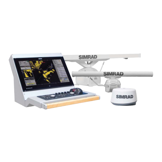
- Page 1 ARGUS RADAR SYSTEM User Manual ENGLISH navico-commercial.com...
-
Page 3: Preface
Preface Disclaimer As Navico is continuously improving this product, we retain the right to make changes to the product at any time which may not be reflected in this version of the manual. Please contact your nearest distributor if you require any further assistance. It is the owner’s sole responsibility to install and use the equipment in a manner that will not cause accidents, personal injury or property damage. - Page 4 Safety precautions The Argus radar is connected to 115 VAC or 220 VAC - 50 or 60 Hz power; therefore, before starting any work on the equipment, make sure that the power supply is switched off. The system is equipped with fuses protecting the electronics devices from short circuits, which may damage the equipment or cause fire.
- Page 5 High voltage Radar equipment includes high voltage that can cause injury or loss of life. Danger exists only when the units are opened and exposing internal circuits, as when servicing the equipment. The ARGUS Radar has been carefully designed to protect personnel from possible injury from high voltages.
- Page 6 Warning information The following warnings will appear in the text of the technical manuals, and are repeated here for emphasis. Warning: Use extreme care when working on the unit once the cover has been opened. The magnetron assembly operates at voltages that may prove fatal. Warning: Beware of high voltage capacitors.
-
Page 7: Table Of Contents
Contents Preface General information Introduction Abbreviations How to read the system version Available versions Physical description Monitor unit Control panel (keyboard) Core unit General functioning description Target and data display Video signal processing Failure procedure Watchdog function Technical characteristics Basic operation Keyboard controls and indicators Procedure to switch on the system Monitor presentation (4:3 system) - Page 8 Latitude and Longitude or ETA and TTG Tracking section Target tracking Target track and AIS association mode CCRP Position (Consistent Common Reference Point) Parallel index menu Main menu Radar configuration Personal settings Video level equalization Layout Brilliance settings Day color Antares PCB info Sharing About Argus...
- Page 9 A or B combination A and B combination Sector combination A and / or B combination Measurement Radar echo measurement Measurement by means of range rings and bearing scale Measurement by means of the cursor Measurement by means of the ERBL 1 or 2 More target data measurement Cursor section Cursor...
- Page 10 129 Alert and system failures 129 External bridge alert systems 129 Bridge Alert Management (BAM) 129 Bridge Navigational Watch Alarm Systems (BNWAS) 129 Type of alerts 129 Alert notifications 130 Acknowledging alerts 131 The Alerts list 131 Audio On/Off 131 Radar presentation failure 131 Alphabetic alarm listing 133 List of wrong operation messages 135 Operating modes fallback...
-
Page 11: General Information
General information Introduction The ARGUS Radar is a radar indicator with a presentation based on a raster scan principle. The advantages of using the raster scan principles to produce a radar display are as follows: • true daylight presentation • continuous display of radar video •... -
Page 12: Abbreviations
Abbreviations Navigation related information is very often presented using the standard terms or abbrevia- tions. In the following table you will find the most common abbreviations and the ones used in this manual. Abbre- Abbre- Terminology Terminology viations viations Acknowledge Electronic Chart Display And Information ECDIS System... - Page 13 Abbre- Abbre- Terminology Terminology viations viations Label Range Limit Rate Of Turn LOST TGT Lost Target Range Rings Long Pulse Route Metres Receiver Maps SAF CON Safety Contour Minimum Search And Rescue Minutes SC/SC Scan To Scan Marker SDME Speed and Distance Measuring Equipment Man Overboard Select Medium Pulse...
-
Page 14: How To Read The System Version
How to read the system version The function of the System Version menu is to recognise the program and the version run- ning within the system. To display the System Version: Open the menu by pressing the relevant button Press the About Argus button. This menu summarises all the programs running within the system. -
Page 15: Physical Description
Keyboard Unit on which the hardware of the Control Panel is mounted. • Scanner Unit – not included. Refer to Simrad ARGUS Radar Scanner – Technical Manual. Monitor unit The Argus Monitor Unit represents the visual interface between the Operator and the Equip- ment. -
Page 16: Target And Data Display
the selected transceiver represent the data on which the equipment operates. The signal process mainly consists of two steps: • the Video Signal Processing • the Automatic Target Tracking. The results of the signal processing are both visualised on the monitor and sent to the Auto- matic Target Tracking circuits. -
Page 17: Technical Characteristics
Technical characteristics General description The ARGUS Radar fully complies and exceeds IMO recommendations. • IMO-Resolution A.278 (VIII), A.694 (17), A.823 (19), MSC 191 (79), MSC 192 (79) • EN 62388 Ed.2.0, 2013 • EN 62288 Ed.2.0, 2014 • EN 60945 Ed.4.0, 2002 incl. Corr.1, 2008 •... - Page 18 Technical specifications Dual VRM from 0 to 96 NM with digital readout VRM resolution 0.01 NM VRM accuracy 1% of range scale in use Azimuth resolution 0.1° Dual EBL with independent 0-360° true or relative digital readout EBL resolution 0.1° Trackball Polar and Geographic coordinates continuously displayed Diagnostics...
- Page 19 Technical specifications Simplified conning infor- Graphic display of sensors, e.g.: • mation Wind sensor • Steering Gear • Heading sensor • CCTV Input • Echo sounder • SDME sensor Additional PPI Additional PPI with the same functions as the main PPI, including the possibility to interact with different TXRXs at the same time ECDIS interface Function for complete integration with an ECDIS system connected via LAN...
- Page 20 Technical specifications Type approval: IEC 60945 (General Requirements) IEC 62388 (Radar Performance) IEC 61162-1/2 (NMEA interface) Warning: Highest mast position is good for long range detection, but it heavily affects the detection in sea clutter. For optimal detection in sea clutter, suggested antenna height from sea level is around 20 m.
-
Page 21: Basic Operation
Basic operation Keyboard controls and indicators 8 12 9 10 14 11 SYSTEM BRILL GAIN RAIN TUNE POWER CHART RADAR CONN OTHER TX ON SHOW EVENT AUDIO LAYER DISPLAY TRACKING TM / COURSE HEAD NORTH PRES FNCT 1 FNCT 2 FNCT 3 FAIL CANCEL... - Page 22 Control or Ref. Description and function indicator Anti-Sea Clutter by reducing the gain at minimum range gradually returning to normal. Push to toggle Manual/Auto modes. The gain varies with the distance according to a predetermined curve and in an amount proportional to the setting. When the potentiometer is turned fully counter clockwise, the gain is uniform over the entire screen.
-
Page 23: Procedure To Switch On The System
Procedure to switch on the system Switching on the main power switch placed on the core unit, the system will boot and the Standby window will appear. Pushing the POWER button the system will switch between Standby and Sleep mode. When the system is in Sleep mode it appears to be powered off, but the electronics are still on, waiting for the actual Power On mode request. -
Page 24: Monitor Presentation (4:3 System)
Monitor presentation (4:3 system) The monitor function is to visualise all necessary information to carry out the scheduled navi- gation and show information related to targets, own ship, settings and measurements, etc. According to the procedure described in the previous paragraph, clicking the TX ON button will turn on the yellow LED and set the scanner in transmit mode. - Page 25 1) Own ship 2) Help line 3) Operating mode 4) Cursor 5) Tracking 6) Main menu control 7) Displaying information 8) Video processing 9) Alerts/System status/Failure 10) Presentation modes System data area sections | 23 Basic operation | Argus Radar Operator Manual...
- Page 26 System data area Ref. Sections Function Own ship In this section all parameters regarding own ship are indicated: AIS operating mode (ON/OFF, if connected) • Heading • Speed and course • Own ship geographic position • UTC or Local time •...
-
Page 27: Monitor Presentation (Wide Screen)
Monitor presentation (wide screen) This type of configuration has the same basic characteristics as the 4:3 monitor, but with the availability of a larger area in which to view the different sensors. Monitor display - Wide screen The window displayed can be divided into the following two main areas: PPI area in which the video radar is displayed. -
Page 28: General Operating Procedures
Area 1 Sensor information 2nd PPI mode Main menu and sensor area information Area 3 Sensor information System data area sections System data area Sections Function Area 1 Sensor information In this area, it is possible to view up to two sensors 2nd PPI mode. -
Page 29: Labels
Bi-stable button (On and Off) Menu button List button The different type of buttons look very similar and when pressing them, the operator can see that the button has been pressed. Button style when pressed Button style when focusing (cursor pointing) Almost all of the buttons activate their action when they are released after being pressing, so the operator has the possibility to move the mouse pointer away and not execute their action even if he already pressed them. -
Page 30: Switch Buttons
It is also possible to modify the value by passing with the mouse pointer over the value itself. The possible choices will appear in the Help line, in this case: Switch buttons These widgets look very similar to the previously described buttons, but their behaviour is very different: Normally they form a group in which only one is selected. -
Page 31: The Three Function Keys On The Keyboard
the cursor over them is represented by a normal up-oriented arrow. The focusing on the prog- ress bars is shown by drawing a frame inside them. Video processing (Accepts input) Video processing (Accepts input) Brightness control (Accepts input) Screen capture (Indication only) The three function keys on the keyboard ¼... - Page 32 LEFT SK CENTER SK RIGHT SK Truncate Select Untruncate When Truncate mode Select Parallel Indexes; When Truncate mode is enabled on Parallel keeping it pressed, the is enabled on Parallel Index sub menu, the line can be moved Index sub menu, the parallel index pointed parallel index pointed by the cursor will...
- Page 33 LEFT SK CENTER SK RIGHT SK Maps List Show Map Clear Map Open maps list menu Display selected map Close and undisplay selected map Maps List Hide Map Clear Map Open maps list menu Hide currently dis- Close and undisplay played map selected map Zoom Out...
-
Page 34: Focusing Function
LEFT SK CENTER SK RIGHT SK Ais Setting Assoc Off Open Training menu Switch off association with data from AIS or Target tracking for target Filter Off Filter On Off Disable filter for sym- Enable filter for sym- Bypass the function bols presented bols presented TT Source... -
Page 35: Menu Window
Menu window Basically, all opened menus are windows, which have a title in a color different to the rest of the window (pos. 1), a back pushbutton (pos. 2) used to return to previous menu and an escape pushbutton (pos. 3) used to close the window. The remaining area (pos. 4) normally contains buttons, labels or any other kind of widgets or items. -
Page 36: The Button's Label
In case the operator enters an incorrect password, a Wrong Message error will be displayed. The ESC labelled button closes the window and the data is not applied. The backspace button (labelled with a left arrow) deletes the last digit. The DEL labelled button deletes the entire data inserted. -
Page 37: Own Ship Section
Disabled AIS lost alert page 91 Disabled AIS danger auto-activation page 91 Presentation reset page 62 System status / System failure page 29 Own ship section In this section the operator has a fast read-out of all the information concerning Own Ship (See “System data area sections”... -
Page 38: Speed
Gyro No Preset. Means that the connections are detected correctly, but the operator need to • preset the gyro value as described above. Gyro No Ref. Means that no reference is detected for the three phases of the gyro signal. A •... -
Page 39: Speed Source Selection
Speed Over Ground and Course Over Ground, the information between parenthe- ses indicate the equipment which is sending the sentence (OSD sentence) and the type of sensor which the info is coming from. Manual Speed, the speed source chosen by the operator is the manual one. -
Page 40: Log Speed
Manual Speed, which is not allowed if using AIS on board. • Auto Drift, which is not allowed if using AIS on board. • EPFS Speed. • The speed source selected is indicated by the green “√” tick on the yellow background. Furthermore, it is possible to set a Manual Drift speed and angle, but only with: Manual Speed;... -
Page 41: Epfs Speed
Select “Auto Drift” and the speed displayed in own ship window will be the result of the calculation of the Ref Target relative speed inverted by 180 degrees. Pressing “Ref Target Sel” with no tracked target, or no target selected or a moving target se- lected, the system will indicate “Wrong: No Steady Target”... -
Page 42: Course
¼ Notes: The default source of speed is the speed log, and it is the one selected after every start-up; • after a switch from standby to TX-On the last selection is reloaded. An SDME speed over the ground based on acoustic sensors has limited depth range and •... -
Page 43: Help Line Section
Help line section The function of the Help line (See “System data area sections” on page 23) is to make sug- gestions to the operator on the actual functions of three function buttons. The main functions are described in “The three function keys on the keyboard” on page 29. Operating mode section There are two switch buttons under the help line (See “System data area sections”... -
Page 44: Tracking Section
Tracking section The AIS label shows the AIS operating mode. If an AIS device is connected, a progress bar in- dicating the number of targets will be displayed, otherwise the information displayed is “OFF” (See “System data area sections” on page 23). The maximum number of targets that can be acquired is 300 (CAT1&2) or 120 (CAT3);... -
Page 45: Parallel Index Menu
Parallel index menu In the graphic symbols menu, it is possible to set up four parallel indexes. The Parallel Lines function shows the distance between own ship and the coastline, or one or more ships when navigating. This function is particu- larly useful when navigating in limited or restricted waters and navigating in a traffic sepa- rated zone. -
Page 46: Personal Settings
Personal settings Pressing the “Personal Settings” button, the following window will be displayed. Personal settings menu This menu gives the possibility to customize the ARGUS Graphic Interface, changing the col- ors, the brilliance of a part of the interface and so on. Obviously, these settings depend on the preferences of the operator. - Page 47 “Decrease” always remains on the left and “Increase” always on the right. ¼ Note: This setting will have effect after a restart of the system, it is not possible to see the effect in real time. Menu color palette Pressing the Menu Palette button, a list with the following options will open: Menu: Light Blue Menu: Dark blue Menu: LightGreen...
-
Page 48: Video Level Equalization
PPI black background When this feature is selected (default), the PPI background will always appear in black, no matter which video palette is selected. Checkbox deactivated: The PPI background Checkbox activated: The PPI background will be according to the selected palette color. will always appear in black. - Page 49 Cursor rest position The function of this button is to define a position for the trackball pointer to move to after a defined timeout, which will allow the operator to always know the exact position of the cursor. To turn on the Cursor Rest Position function, press the “Cursor Rest Pos Off”, which will change to “On”...
- Page 50 ¼ Notes: The same function could be stored more than once in a FK, e.g. if “True Vector” is stored on • all of the 6 functions of FK1, pressing FK1, the vectors presentation is changed to True mode 6 times, with no other change visible to the operator.
-
Page 51: Layout
Help Off/On Each button is labelled in order to visualize the main function it performs when pressed. If this function is activated (Help On), further information is provided when hovering the cursor over the buttons for more than one second. A help label will be displayed, enhancing the informa- tion for the button where the cursor is positioned. -
Page 52: Brilliance Settings
Brilliance settings Pressing the Brilliance Settings button will open a menu where the operator can adjust the brilliance value of: Keyboard dimmers, Own ship symbol, Navigation symbols, Video radar, Tracking symbols, ERBL and Menu interface. The Brilliance Settings Menu appears as in the following image, with seven different progress bars, one for each brilliance value. -
Page 53: Sharing
Sharing In this mode (Main menu), after setting the Video Maps, Conning Task Configurations and Personal Settings on the radar, you can then share these settings with other existing stations, simply by pressing the Synchronize pushbutton - see below example: Once you have sent the new configuration, the recipient has to accept it by consenting to the new setting. -
Page 54: Ecdis Interface Functions
ECDIS interface functions When the unit is configured to be connected with ECDIS, a new pushbutton will be available in the lower part of the main menu. Press the ECDIS pushbutton to opent the ECDIS menu. Main menu with ECDIS The menu contains two checkboxes to enable streaming of the synthetic video to the ECDIS console. - Page 55 Maps viewed through ECDIS with different scales On the left it shows two maps representing the same course but with different scales. Both of them show mainly: A red dotted line (1) representing the course of the ship • Red circles (2) inserted above the dotted line (1), representing the points in which the ship •...
-
Page 56: Conning Menu
Conning menu The Conning Menu button is only available for the wide screen system. In this mode, the operator can configure the available areas on the system data area section, entering the tasks to be set into the dedicated areas.The sensitive areas for which we can configure our Tasks have been highlighted in the figure below. - Page 57 By entering the Conning Tasks menu configuration, you can enable the “Conning Task Editing mode”. This function means it is possible to intervene in each of the three areas by inserting the required tasks, simply selecting them from a list, which is opened each time the trackball’s center key is pressed.
- Page 58 Task Description Heading: The window shows the ship’s heading in relation to geographical north. Haven and bottom Track: The window shows the speed through water (STW) and the speed over ground (SOG). Docking: The window shows the speed over ground (SOG); this is used during docking manoeuvres.
-
Page 59: Task Window Movement
Task window movement Once a task has been selected, it can be moved inside the sector itself; positioning the cursor at the top left corner of the task and pressing one of the two “Operating Pushbuttons” it is possible to drag and drop the selected task window using the trackball (see figure to the left). Selecting the bottom right corner of the task window, it is possible by pressing one of the two “SK keys”... -
Page 60: Additional Ppi
Additional PPI 2nd PPI mode This type of representation is only available in wide screen mode and it offers the possibil- ity to view a different type of presentation. Almost like having two radars. The Additional PPI can show different radar scales, orientations and stabilization. The additional PPI has separate video processing and controls to have optimum conditions for specific use. -
Page 61: Customizing Radar Control Settings
Zoom To access this option, enable the “Zoom” checkbox. A fixed size zoom window will be shown in the menu area. In zoom mode, a square will be drawn on the PPI indicating the area which is zoomed. Use the center trackball key to move the area, right key to increase zoom and left key to decrease it. - Page 62 The following functions are included when you save a user setting: Function Default settings Band X-band Collision warning On (limits CPS 2 NM, TCPA 12 minutes) Display mode of PPI True motion, north up Display of maps, navigation lines and routes Last settings EBLs Off...
-
Page 63: Radar Presentation And Video Processing
Radar presentation and video processing Presentation and visualization options section In the lower section of the system data area the visualized buttons represent different func- tions and operations related to the presentation options. Orientation and motion modes The function of this line (“System data area sections” on page 23 and “Shortcuts” on page 27), normally labelled with the actual orientation and motion mode status, i.e. -
Page 64: North Up
North Up Operating in North Up mode, the heading line on the PPI is oriented according to own ship heading obtained from the Gyro compass, the 0° indication on the PPI represents North. When own ship turns, the heading line changes its direction according to the ship’s heading and the radar image remains stabi- lised in azimuth. -
Page 65: The Row Under Ppi Area
The row under PPI area Under the PPI area there is the row for the presentation modes, in which the following con- trols are located (note that widgets can be shown from left to right or viceversa, depending on the currently used layout): Range Scale Increase/Decrease Range Rings ON/OFF PPI Centre/Off... -
Page 66: Reset/Tm Reset
50% of the radius, anywhere on the screen and in this case the label indicates “PPI Offcentre”. The operator cannot offset the centre when the radar display is set to the longest range scale (96 NM). The centering of the PPI can be changed by means of the PPI section (OFF CENTRE and CEN- TRE buttons), of the keyboard, or by selecting PPI mode by means of the SKs. -
Page 67: Video Processing Section
adjustment should be performed about 10 minutes after the radar has been switched on and once the magnetron has warmed up properly. To better tune the radar manually, the operator should set the range to 24 NM and set the gain in order to show the threshold of noise. -
Page 68: Rain
Rain The rain progress bar indicates the intervention of the Anti Rain Clutter processing. In case of automatic Anti Rain Clutter processing, the inscription “AUTO” will precede “RAIN” inside the progress bar. Marine radars are sensitive to rain drops, snow flakes and fog, the returning signal is some- thing similar to a big hazy spot of video, which can saturate the receiver and mask all targets covered by the humidity. -
Page 69: Sea
The function of this control is to reduce sea returned signals. The sea waves return a spot simi- lar to the one of rain, but with a different behaviour. The spot drawn on the screen is normally around the PPI origin and its intensity decreases with increasing range. The function of the sea control is to cut the video detected under the anti sea clutter curve, its effect is stronger close to the origin (antenna) and weaker going farther in range, following the sea clutter behaviour. - Page 70 remain under the clutter, while if the setting is too high, both sea clutter and targets will dis- appear from the display. In case of a too strong suppression of clutter, the dark area displayed around own ship may not show potentially dangerous nearby targets. The proper setting of the sea clutter should be such that the clutter is seen as small dots, and small targets will become distinguishable around the ship.
-
Page 71: Video Preset
Video preset To switch between available video presets the operator needs to focus on the Video Preset widget and click with left and right SK to select the desired condition. Options available are: Harbor, Near Range, Med Range, Far Range, Rough Sea, Ice. The option “No Preset”... -
Page 72: Scan To Scan Correlation
Sweep to Sweep Correlation Target Enhancement The above figures show zooms of the areas delimitated by the white rectangles drawn in the previous four figures, in a part of the radar image in which some small and weak echoes are on the limit to be visible with IR off, definitely not visible with IR on and with Sweep to Sweep Correlation and very visible with Target Enhancement. -
Page 73: Mutual Radar Interference
radar echo smaller than 30 m with a speed of 20 knots, will move too fast and therefore will not be visible. The same echo having, for example, maximum dimension of 25 m will be correctly displayed if the antenna rotates at 40 rpm (HSC), as the minimum dimension indicated in the table is 16 m. - Page 74 radar, the SART immediately transmits a response, which is swept repetitively across the com- plete radar frequency band. The response is made by a first rapid sweep (0.4 µs) through the band and a relatively slow sweep (7.5 µs) through the band back to the starting frequency, repeated for a total of twelve complete cycles.
- Page 75 Furthermore: When only the responses generated by the slow sweeps are visible (when the SART is at a range greater than approx. 1 NM), the position of the SART must be estimated 0.64 NM closer than first dot. Whereas, when the distance from the SART is short and the responses gener- ated by the fast sweep are visible, the position of the first of these will be no more than 150 m beyond the true position of the SART.
-
Page 76: Racon (Radar Beacon) Video Presentation
Particulars of SART sweeps The information described in this paragraph has been extracted from IMO SN/Circ 197, Opertion of Marine radar for SART detection. RACON (Radar Beacon) video presentation The video processing Scan to Scan Correlation could suppress the Racon Warning: return on the display, and may need to be shut off. -
Page 77: Video Processing Menu
Racons installed on buoys are normally active for 20 seconds, and then off for the next 20 seconds and so on. Racons installed on shore, where battery life is not a factor, are normally programmed to operate 75% of the time. Racons are usually not programmed with a duty cycle greater than 75%, in order to ensure that the response never completely masks an important radar target. -
Page 78: Which Preset Is The Right One
Function Parameter Setting Gain Manual 80% State 2 50% Rain Manual 0% Long Range Interference Rejection Sweep to Sweep Scan to Scan Power Boost Gain Manual 70% State 3 50% Rain Manual 50% Rough Sea Interference Rejection Scan to Scan Power Boost Pull down Gain... -
Page 79: Txrx Interswitch Menu (Standard)
As per above example, you may save modified settings as user default by pressing Save, and later on return to factory default at any time by selecting the button “Reset Harbour” to “Fac- tory default”. TXRX interswitch menu (standard) Pressing TXRX and Interswitch button (“Main menu with ECDIS” on page 52), normally labelled “TXRX n mode”, where “n”... -
Page 80: Power Normal/Boost
The performance monitor ring should have a missing angular sector of some 60° to 100°. This missing sector is due to the RF beam really transmitted by the antenna. Any RF power degradation between the magnetron and the antenna output results in a smaller angular ring interruption. -
Page 81: Txrx Data
TXRX data By pressing the TXRX data button, the “TXRX 1 DATA MENU” will be displayed; in this window transceiver parameters such as the Antenna, PRF, Magnetron Lifetime etc.) are shown. These parameters will be utilised in order to set specific alarms (such as if the internal temperature is higher than 70°C). -
Page 82: Tracking And Video Processing Operation In Combination And 2
It is possible to see the window shown in above figure by selecting one of the two transmit- ter signal presence indicators using the shortcut in the bottom right, in the row under the PPI area. Row PPI area The combination of the four signals is important, as it optimises the ability to view a better quality image on the PPI in weather conditions such as rain or rough seas. -
Page 83: Or B Combination
A or B combination Once the correct setup on “Interswitch menu” has been selected from the menu with the antennas you wish to use for this purpose, under the item “Combination Type”, select the de- tection mode, such as “A or B”, for example. The combined picture will display echoes received on both transceivers also if an echo is visible only from a single radar antenna. -
Page 84: Sector Combination
Sector combination Sector combination (interswitch setup menu in sector combination) This combination mode, known as “Sector”, is used to permit a full radar vision on 360° in case blind sectors are present or one or more blanking sectors are configured during installation. Blind sectors are caused by obstacles situated in front of the antenna’s radiation beam, reduc- ing the possibility of signal reception on the radar presentation. -
Page 85: And / Or B Combination
A and / or B combination A and/or B combination (interswitch set up menu in sector combination) This combination mode is used to get both benefits of the and/or combinations. Up to the range where the sea clutter can be present, which depends of antenna type and height, the combination is following the “and”... -
Page 86: Measurement
Measurement Radar echo measurement The position, speed, course, distance and bearing of radar echoes can be performed in several ways: Measurement by means of range rings and bearing scale • Measurement by means of the cursor • Measurement by means of the ERBL 1 or 2. •... -
Page 87: More Target Data Measurement
¼ Note: On the keyboard, the EBL and VRM can be adjusted with two (encoders) placed at the bottom corners of the panel. Making the adjustments from the keyboard is more accurate and we suggest using this method instead of dragging the markers. The “EBL n”... -
Page 88: Cursor Section
Cursor section In the cursor section of the system data area, all the parameters relevant to the cursor are displayed. The information displayed are described in the following sub-paragraph. Cursor The cursor polar position (range and bearing) is displayed and it can be toggled between True and Relative. -
Page 89: Parallel Indexes
In this example, the ERBL 1 is geographically referenced and the ERBL 2 is locked to own ship. The same function is available from the cursor menu - see below example. When the geographic position or the heading is not available, the ERBL center will be reset to OS Lock. - Page 90 When the parallel index is selected by means of the cursor it will be possible to truncate the remaining line exceeding the cursor position but using the Truncate mode. The list Set all Parallel Index to HL enables one of the possible fast alignment modes. The selections available are: •...
-
Page 91: Range Rings
lowing the Help line (centre SK says “Select”), the operator will be able to hook the line by pressing the centre SK and keeping it pressed. Then, moving the mouse, the line will turn and it will be released when releasing the centre SK. To move the line at the right range, perform the above operation hooking the point drawn on the index line. -
Page 92: Tracking
Tracking General information Radar target tracking facility The radar system includes a facility for acquiring and automatically tracking radar echoes. Each radar target center is used to estimate the relative speed and direction for anti-collision purposes. Tracking error sources and effects There are some factors that can generate errors and confusion in tracking and/or reduction of target detection capability to the radar operator. -
Page 93: Tracking Operation In 2 Nd Ppi Zone And Under Video Combination Mode
These effects, when they are an extension of the main echo, can cause momentary errors for the tracking, course and speed values given by the tracking can become unstable. Normally the problem can be eliminated or strongly reduced by an accurate adjustment of the sea control. Blind sectors Funnels, masts (when located near the radar antenna) may cause blind or shadow sectors, where the target visibility may be completely lost or strongly reduced. - Page 94 system is based on the VHF channel, RX one and TX the other, and uses Self Organising Time Division Multiple Access (SOTDMA) technology to meet this high broadcast rate and ensure reliable ship to ship data exchange. Every channel is divided into time slots. During these slots, information related to the ship and information from other ships in the area are exchanged.
-
Page 95: Tracking Target Symbols
Operating All information is presented on the monitor’s screen by means of a serial line. It is necessary to set up the system properly, in order to receive this type of information. The AIS function is automatically enabled when one or more AIS are received. Their number is shown in the tracking section of the system data area near the “AIS”... - Page 96 Symbol Description AIS target - Dangerous, indicated with bold line and with red color. The symbol flashes until the target alarm is acknowledged by the operator AIS target - Lost, indicated with crossed lines centered on the target symbol. The symbol is located at the last received position from the target AIS target - Selected, indicated with a square (dotted line) around the target symbol...
- Page 97 Symbol Description Physical AIS AtoN - Port hand mark Racon err Physical AIS AtoN - Racon failure Physical AIS AtoN - Racon Physical AIS AtoN - Safe water Physical AIS AtoN - South cardinal mark Physical AIS AtoN - Special mark Physical AIS AtoN - Starboard hand mark Unlit Physical AIS AtoN - Unlit (failure of lights)
- Page 98 Symbol Description Reference target Signal station Trial manoeuvre in execution (flashing). Virtual AIS AtoN, basic shape Virtual AIS AtoN - East cardinal mark Virtual AIS AtoN - Emergency wrek mark Virtual AIS AtoN - Isolated danger Virtual AIS AtoN - North cardinal mark Virtual AIS AtoN - Port hand mark Virtual AIS AtoN - Safe water Virtual AIS AtoN - South cardinal mark...
- Page 99 AIS target Description of symbol Indicated by an isosceles, acute angled triangle with its centroid rep- resenting the target's reference position. The most acute apex of the Sleeping triangle will be aligned with the heading of the target or with its COG, if target heading information is not available.
- Page 100 Warning: The operational availability of the tracking function is continuously checked to warn the operator in case of malfunction. Various failures can be detected and displayed inside the system failure window. The fail- ures are listed and explained in Chapter 7. Operating with the AIS target ¼...
-
Page 101: Target Overload
It is possible to select own ship (always identified as target NR. 1), by means of the AIS list (“AIS list” on page 110). In the targets data window, the fields related to speed, bearing, CPA and TCPA are obviously empty. But own ship’s data visualisation is useful in order to see if own AIS is operating correctly. -
Page 102: Past Positions
The selection indicates the time for the trails to fade out. The picture on the left shows four targets moving in North direction, the lighter blue repre- sent the trails. The lower intensity of the color, the longer time since the target was in that position. -
Page 103: True/Relative Vector
Placing the trackball cursor over the label, the help line will change to “Decrease”, “Enter Value” and ”Increase”; therefore, using the left and right SKs the operator will change the value of a unit for each click. Pressing the centre key, the alphanumerical keyboard will be visualised to directly entering a new value. -
Page 104: Anchor Watch
• Trial Manoeuvre (page 104) • AIS and Radar Target Association (page 109) AIS only operations: • AIS On/Off (page 110) • AIS List (page 110) AIS limit priority and AIS filetering: • AIS Limit Priority (page 111) • AIS Filtering (page 111) AIS options: •... -
Page 105: Minimum Safety Menu
Minimum safety menu This is a function for radar targets and AIS, which allows visualising and setting the threshold of CPA and TCPA that defines when a target will be considered dangerous. If for example, the values are set to 0.1 NM and 10 minutes (default values, re-set at every start-up), when a target has a CPA of less than 0.1 NM and at the same time a TCPA of less than 10 minutes, the “Danger Target Alarm”... -
Page 106: Trial Manoeuvre
When Guard zone is chosen, any radar echo or AIS target received near the same position for 3 consecutive scans within the area, will automatically be acquired and, in the alarm area, the alarms “RADAR TRACKED TARGET AUTO ACQUIRED” and “TARGET IN GUARD ZONE” are activated and the symbol is drawn in red color as a reversed triangle (only RADAR TARGET). -
Page 107: Manual Trial Manoeuvre
To obtain realistic results, the ship’s turn delay and the time required for evaluation and deci- sion, are taken into consideration by means of a delay that can be manually inserted. The Trial Manoeuvre functions allow course changes of up to ±135° from the original course, to be tested. -
Page 108: Automatic Trial Manoeuvre
manoeuvre. With the “Trial Exec” button released the real actual values are displayed. In case one of them is dangerous, the correspondent label is highlighted in red color. The Minimum Safety can be set changing the “Minimum CPA” and “Minimum TCPA” values in the Trail Manoeuvre Menu. - Page 109 • If during the manoeuvre any target is dangerous, the manoeuvre will continue • Own ship vector will be displayed with the computed safe trial course, and at the estimated position, where the manoeuvre ends • All target vectors on the PPI are displayed at their estimated position, according to the trial manoeuvre end, thus allowing the situation to be evaluated •...
- Page 110 Automatic Trial Manoeuvre scenario - Before and after the execution The operator needs to understand if a steering to 0° is safe, so he performs the manual trial manoeuvre to foresee the situation at the end of the steering he intends to do. Automatic Trial Manoeuvre scenario During and at the end of the manoeuvre, the target 3 is not dangerous, and own ship seems to safely cross the bow of target 3, with a CPA of 0.3 NM.
-
Page 111: Ais And Radar Target Association
Manual Trial Manoeuvre scenario - After the execution AIS and radar target association The system can visualize up to 100 radar tracked targets and 300 AIS targets (depending on the category, these limits could be different, see table on page 15). It is possible to merge a radar target and an AIS target retaining the same ship, in order to: •... -
Page 112: Ais On/Off
In order to properly operate with tracking data association, the operator has to fill in three values in the above window: • Max Delta Range (0.07 NM in the Figure) • Max Delta Speed (2.5 KT in the Figure) • Max Delta Course (11.2°... -
Page 113: Tt Target List
Selecting the items of the list, the corresponding target will be selected. Closing the list, the targets data window will be displayed. This means that it is possible to select more than one item from this list. The AIS list is a tool where the operator can take a quick look at the AIS situation around own ship, and it can list targets farther than the maximum range scale of the radar. -
Page 114: Ais Options
CLASS B Only the AIS targets of CLASS B will be affected by the filter. SPEED By selecting SPEED, a menu will appear requesting to select the minimum value for any target in KT. Targets with a lower speed than this value will be hidden. -
Page 115: Route Presentation And Waypoint Data
ID code Displayed as a number from 1 to 40 for radar target tracks and from 1 to 200 for AIS tracks. For the radar tracked targets it is assigned by the system incre- mentally, the last one plus 1 (if under 40), even if lower numbers are free. For the AIS targets it is the lowest number available at the first reception. -
Page 116: Predictor
The route is immediately displayed after been received from the ECDIS/EPFS and disappears automatically after a 40 seconds timeout. The route is presented according to own ship’s geographic position and the range scale in use. Inside the symbols window, the Waypoints Data button is visible when a route has been received from EPFS. - Page 117 only on AIS targets. The various possibilities are further explained later in this paragraph • Status. Indicates the navigation status of the target. The information is available only on AIS targets. The various possibilities are further explained later in this paragraph. The switching between the presentation of 2 and 4 targets is easily performed by means of the SKs, placing the trackball cursor in the target data window and looking at the Help line.
- Page 118 Pressing the left SK, a new yellow window will be displayed with the available extended data about the target related to the field of the target data window where the SK has been pressed. Hold the SK to keep the extended data window on the screen; its releasing will cause the closing of the window.
- Page 119 With the 4 targets mode, pressing the left SK in the field of an AIS target, the extended data window will appear as follows. The information displayed are: Latitude Longitude BCT. When selecting a radar tracked target, which has been acquired less than 1-3 minutes before (not yet steady), some fields of the target data window will as a result be unreliable until the expiring of the three minutes.
- Page 120 quently from “R” to “T”. The bearing of the selected targets changes along with the selected motion mode: • Relative Motion Relative Bearing • True Motion True Bearing. Also the value of speed and course could be Relative or True, and the letter preceding them will change consequently as well.
-
Page 121: Maps
Maps General information The Video Maps are navigation graphic tools, composed by lines, text and symbols, to be superimposed on the PPI. Their purpose is to help the operator to increase the definition of the coasts or restricted or dangerous areas. Each map consists of up to 120 segments, 32 texts and 32 symbols, 184 elements in total. -
Page 122: Create A New Map
• “Map List” opens the Video Maps Menu • “Hide Map” hides the map temporarily from the screen, the Help lines middle suggestion changes to “Show Map” and on the Map Name a “(Hidden)” text is added. Press the trackball’s middle pushbutton again to show the map again •... - Page 123 accuracy just by pressing the “Select Closing Point” button and pressing the right SK in cor- respondence of the first point of the square. The trackball cursor must be placed near to that point, which will close the polygon and the right SK (in correspondence of “Close” of the Help line) must be pressed, when ready.
- Page 124 To move the map: Press the “Shift/Rotate” button and move the trackball on the PPI. The Help line will change to “Posit Adj”, “Undo Adj” and “Angle Adj”. “Adj” stands for Adjustment. Press the left SK and the map will be anchored to the trackball. The Help line will show “Apply Shift”, “Undo Adj”...
-
Page 125: Operating With A Selected Video Map
The system will not accept the Dead Reckoning choice, if the ship speed information is miss- ing, the Geographic Map choice, if the EPFS signal is missing, and neither of them will be accepted, if the Gyro input signal is missing. When the Geographic Map type is used, another button will appear in the lower part of the Editing Map Menu: “Geo Map Manual Settings”. - Page 126 Appearance of the highlighting (Focusing) of a line of the map. To delete the line, just press the right SK (corresponding to “Cancel Line”) when the line is highlighted. To move the line, when it is highlighted, press the left SK (corresponding to “Hook Line”); note that only the extremity of the selected side will be hooked and the other end of the segment will remain in its position.
-
Page 127: Geographic Map Manual Settings Menu
Once the modifications are finished, the map must be saved. If the map was under construc- tion without any name yet, the system will just ask to insert a name for the new map. Otherwise, if the map has been loaded from the memory and therefore already has a name, the system will ask to save the old map and updating it with the new modifications or save the current map as a new one, consequently asking for a new map name also. -
Page 128: Selection And Movement With The Trackball Cursor
While this menu is visible on the PPI, an object for each type is selected and the highlighting helps to find them on the screen. By default, the first line, the first text and the first symbol are automatically selected (as shown in the above picture). To select other elements and to move them, the operator has two different ways, which can be used independently: Selection, anchoring and dragging with the trackball cursor and the SKs. -
Page 129: Selection And Movement By Means Of The Editable Labels And Buttons
Moving the Trackball with the point hooked Releasing the point Clicking on it again, the object will be hooked to the trackball cursor again (the lines will not move while the pointer moves, but the highlighting symbol will). Once moved to where desired, press the left SK again to release it in the new place. -
Page 130: Import And Export Of A Map
Append New Point After The Last Point. The new point will be placed in the same position of the last point of the map, creating two points which are intended to be the start and the end of the new segment. The operator can move them as desired. Import and export of a map To transfer a map, open the USB Storage Menu by pressing the Map USB Sharing pushbut- ton inside the Video Maps Menu with a USB memory stick inserted into the USB port on the... -
Page 131: Alert And System Failures
Alert and system failures In the alert section (“System data area sections” on page 23) the system will visualise all information regarding alerts. The system will continuously check for danger situations and system faults while running. External bridge alert systems The system supports Bridge Alert Management (BAM) and Bridge Navigational Watch Alarm Systems (BNWAS). -
Page 132: Acknowledging Alerts
Warning: Note that it’s not possible to acknowledge a system failure or warning, the only way to turn the fail LED off and remove the highlighting in the system status menu, is to fix the failure. Alert type Icon State Indication Active - Flashing symbol and descriptive text. -
Page 133: The Alerts List
The Alerts list The Alerts list includes a list of active alerts together with a historic listing of the latest 100 alerts. All alerts in the Alerts list include a time stamp. An alert is moved to the historic listing after the alert is removed from the Alerts panel. Audio On/Off Pressing this button, the operator can temporarily silence all alerts for 30 seconds. - Page 134 Alert text Type AIS Not in Use Failure AIS Target Auto-activated AIS Target in Guard Zone AIS Target Lost Anchor Watch Warning BAM Heartbeat Lost Dangerous AIS Target Dangerous Tracked Target EPFS Not in Use Failure Geodetic Datum Failure Gyro Failure Gyro Not in Use Failure Heading Marker Failure Magnetron End of Life...
-
Page 135: List Of Wrong Operation Messages
List of wrong operation messages The following table lists the possible messages displayed when a wrong operation is carried out. This wrong operation does not influence the System. When a Wrong Operation message is generated, the wrong orders button is displayed in its area, labelled with a message cor- responding to the wrong action performed. - Page 136 Message Meaning WRONG: No file by that Name Found No file found corresponding with specified name WRONG: No Item Selected There is no item selected WRONG: No Map Name The map has no name WRONG: No Map Selected There is no map selected WRONG: No More Maps Available No available memory for additional maps WRONG: No More Segments Available...
-
Page 137: Operating Modes Fallback
Message Meaning WRONG: Using No Task Configuration Not possible to use a configuration with no tasks WRONG: Waypoint not received The waypoint has not been received cor- rectly WRONG: You Are in Slave Mode Cannot be executed because the system is in Slave Mode WRONG: You Cannot Be Master Master mode is not allowed... -
Page 138: Maintenance
Maintenance The ARGUS Radar System requires very little maintenance. What is required by the operator is to inspect the equipment carefully and notice every possible anomaly, such as the integrity of the equipment, the presence of rust, missing paint, and loose screws. It is required by the operator to clean the equipment and remove dust, ash and grease, if necessary, by using a soft cotton cloth and alcohol. -
Page 139: Argus Fmcw Radar
ARGUS FMCW radar This chapter contains the main characteristics of the ARGUS FMCW radar system, its operating principles, range of use and limits. The ARGUS system has been implemented with a new source, the FMCW radar, so as to make the perception of obstacles in proximity to the craft during navigation. -
Page 140: Additional Benefits Of Fmcw Radar
The difference between both the currently transmitted and received frequencies, coupled with the known rate of frequency increase, allows a time of flight to be calculated, from which distance is calculated. Additional benefits of FMCW radar Safety • low energy emissions. 1/2 of a mobile phone •... -
Page 141: Fmcw Radar Scanner Specifications
FMCW radar scanner specifications General Description FMCW 3G FMCW 4G Compliance FCC ID: RAY3G4G IC ID: 4697A-3G4G Human Exposure General Public Safety Limit - touch dome anywhere Environmental IEC60945 4th edition 2002-2008 Operating Temperature: -25° to +55°C (-13° to +130°F) Relative humidity: +35°... -
Page 142: Overall Dimension Of Fmcw Radar
Overall dimension of FMCW radar FMCW transceiver radar system installation and settings The procedure how to perform the first time installation and setup of the FMCW transceiver radar system are described in this section. Preliminary operations To start the installation of the FMCW transceiver radar system, check that: •... - Page 143 usable. In other words, they cannot be selected from the Interswitch menu to be visualized in the second PPI because they are not yet activated. To activate the transceivers, enter into the “FMCW Devices Configuration Menu” menu (refer to “Enable the FMCW transceiver radar - A” on page 142). Activate the check box at the top on the left in the menu “FMCW n Inactive”, where n is the number of the FMCW transceiver that is being configured.
-
Page 144: Fmcw Device Configuration Menu
FMCW device configuration menu This menu contains certain useful fields for setting the transceiver and other fields non-modi- fiable by the user that describe characteristics and various data of the analyzed transceiver. Warning: Remember to always press the Accept pushbutton to save the modifications made, otherwise the system will not keep the modifications in its memory. -
Page 145: Utilization Of The Fmcw Transceiver Radar System
The zone relative to the two virtual transceivers has been highlighted by the red box. In fact, both are identified as FMCW 2 and A and B are assigned to distinguish them internally. The data visualized immediately above refer to range B (second service) and pressing the X push buttons the system passes to range A. -
Page 146: Description Of Commands Relative To The Window Of The Fmcw Radar Transceivers
scrolled (if the total transceivers are less or equal to 4, the “Prev” and “Next” buttons will not be visualized). Furthermore, it is possible to select the rotational speed of the transceiver by utilizing the ap- propriate pushbutton (“Interswitch menu with FMCW transceivers” on page 144 -position B). Depending on the model of the FMCW transceiver radar, two or three different rotational speeds of the antenna are available (refer to the table, “FMCW radar scanner specifications”... - Page 147 As you can see, the window contains different buttons, as already described in chapter 3 of the manual, with the additional of some characteristic functions of the ARGUS system, such Color Settings – serves to set the color of the window and the relevant image transmitted from the radar in this mode: a) Press the Color Settings pushbutton b) From the drop-down menu, choose whether to act on “Menu”...
-
Page 148: Limits
¼ Note: Control to be used conscientiously since greater reduction in interference may also mean eliminating weak but important echoes. Target BOOST – This function is used to enlarge the target images on the screen. It has 3 enlargement methods: •...
Need help?
Do you have a question about the ARGUS FMCW 3G and is the answer not in the manual?
Questions and answers
what is tx frequency of 3g Simrad radar
The transmit frequency of the Simrad ARGUS FMCW 3G radar is 9.41 GHz.
This answer is automatically generated