Ferroli ECONCEPT 100 Instructions For Use, Installation And Maintenance
Heat generator running on gas,
pre-mixed with condensation
Hide thumbs
Also See for ECONCEPT 100:
- Instructions for use, installation and maintenance (32 pages) ,
- Installation and operation manual (28 pages)

Related Manuals for Ferroli ECONCEPT 100


Summary of Contents for Ferroli ECONCEPT 100
- Page 1 ECONCEPT 100 EAT GENERATOR RUNNING ON MIXED WITH ONDENSATION INSTRUCTIONS FOR USE, INSTALLATION AND MAINTENANCE...
-
Page 3: Econcept 100 Econcept 100 Econcept 100 Econcept 100 Econcept
ECONCEPT 100 ECONCEPT 100 ECONCEPT 100 ECONCEPT 100 ECONCEPT 100 • Carefully read the warnings in this instruction • In case the unit breaks down and/or functions booklet since they provide important poorly, deactivate it, do not make any attempt information on safe installation, use and to repair it or directly intervene. -
Page 4: Table Of Contents
ECONCEPT 100 ECONCEPT 100 ECONCEPT 100 ECONCEPT 100 ECONCEPT 100 1. OPERATING INSTRUCTIONS .............. 5 1.1 Introduction ....................5 1.2 Control panel ....................6 1.3 Cascade control unit (code 1KWMH18A) ........... 9 1.4 Turning on and off ..................9 1.5 Anomalies ....................9 2. -
Page 5: Operating Instructions
Econcept 100 is a high-efficiency modular heat generator for condensation pre-mixed heating with very low emissions, running on natural gas or LPG. Each Econcept 100 module is equipped with a twin aluminium laminar exchanger and a twin ceramic pre- mixed burner contained in an upright cabinet made of AISI 316 stainless steel. -
Page 6: Control Panel
ECONCEPT 100 ECONCEPT 100 ECONCEPT 100 ECONCEPT 100 ECONCEPT 100 1.2 Control panel The control panel permits displaying the operating status, the setting of the operating parameters of the two exchanger + burner shells inside the module. At the control panel level, operating adjustment and display are entirely independent for the two internal boiler shells. - Page 7 ECONCEPT 100 Operating information on display During operation, without pressing any keys, the display shows the unit’s status: Operating mode Display “D1” Display “D2/D3” Standby System delivery temperature Heating System delivery temperature Standby after heating op. System delivery temperature Accessing the operational menu Pressing the “...
- Page 8 ECONCEPT 100 Adjustments Setting the system temperature To set the system delivery temperature on the single boiler shell, access the operational menu and press the to display parameter 1 – system delivery temperature. On pressing one of the keys , the display starts blinking and the delivery temperature setpoint is displayed.
-
Page 9: Cascade Control Unit (Code 1Kwmh18A)
ECONCEPT 100 1.3 Cascade control unit (code 1KWMH18A) A cascade control unit, available on request, provides advanced control of the operation of the two internal boiler shells. One control unit can handle up to 5 internal boiler shells. Control unit/module combinations are given in the following table. -
Page 10: Installation
2.2 Connection in cascade Econcept 100 is a heat generator designed to operate either singly or in cascade. If the heating capacity required by the system exceeds 90.4 kW, two or more Econcept 100 generators can be connected in cascade (max 5 heat generators), as shown by way of example in the figure. -
Page 11: Place Of Installation
ECONCEPT 100 2.3 Place of installation The generator can be installed directly outside or in a specific room with ventilation openings to the outside as prescribed by current regulations. If there are several burners or suction units that can work together in the same room, the ventilation openings must be sized for simultaneous operation of all the units. - Page 12 To connect a single module (Fig. 5) • After deciding on which side of the Econcept 100 module to make the water and gas connections, connect the flanges with the joining section, contained in the kit, on this side after appropriately welding them onto the system pipes so they are airtight.
- Page 13 ECONCEPT 100 Plumbing connection using one or more generators with a direct pump Delivery/return Flanges with connection Seals Connection side joining section Fig. 6b Condensate outlet connection using one generator Fig. 7 A - Place the pipe 1 Ø40 (not supplied) on the side of the generator.
-
Page 14: Electrical Connections
ECONCEPT 100 2.5 Electrical Connections Power supply The generator should be connected to a single-phase power line, 230 Volt-50 Hz, interposing fuses of max. 3A between the boiler and the line, with a bipolar switch whose contacts have a minimum opening of at least 3 mm. - Page 15 ECONCEPT 100 Positioning the external sensor The external sensor should preferably be installed on the North, North-West wall or on the wall with most of the main living room. The sensor must never be exposed to early morning sunshine and in general, as far as possible, it must not be hit directly by the sun’s rays;...
-
Page 16: Flue Connection
ECONCEPT 100 2.6 Flue connection • Manifold, ducts and flue must be suitably sized, designed and made in compliance with current regulations. They must be made of suitable materials, i.e. resistant to heat and corrosion, smooth on the inside and airtight. In particular, joints must be condensation-proof. In addition, make provision for adequate condensate drainage points, connected via an air-trap to prevent the condensation in the flues running into the generators. -
Page 17: Service And Maintenance
All adjustment and conversion operations must be carried out by Qualified Personnel such as the personnel of the Local After-Sales Technical Service. Ferroli declines any responsibility for damage or physical injury caused by unqualified and unauthorized persons tampering with the device. -
Page 18: System Start-Up
ECONCEPT 100 Boiler parameter adjustment Pressing the “mode” and keys simultaneously for more than 3 seconds takes you to the boiler parameter menu. On then pressing you can scroll through the parameters, and with the and v keys you can edit the settings. - Page 19 ECONCEPT 100 Before igniting the generator: • Open any on-off valves between the generator and the systems • Check the airtightness of the gas system, proceeding with caution and using a soap and water solution to detect any leaks in connections.
-
Page 20: Maintenance
ECONCEPT 100 3.3 Maintenance The following operations are strictly reserved for Qualified Personnel, such as the staff of our Sales Organization and your local After-Sales Technical Service. Seasonal inspection of the generator and flue Have the following checks carried out at least once a year: •... -
Page 21: Troubleshooting
The following table gives information for resolving trouble signalled by the generator. Work on the unit must be carried out solely by Qualified Personnel such as the personnel of the FERROLI After-Sales Technical Service. For work on the unit that requires opening the generator, always have it done by the assistance centre. - Page 22 ECONCEPT 100 Fault Possible cause Cure System delivery • Circulator jammed • Free the circulator by removing over-temperature the plug and making the shaft • Circulator trouble turn with a screwdriver • Check or replace the condenser or circulator System return over-temperature •...
-
Page 23: Technical Characteristics And Data
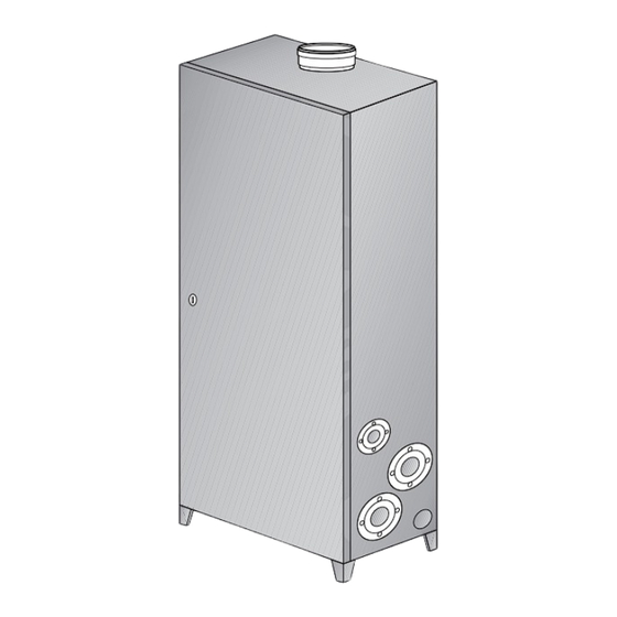
ECONCEPT 100 4 TECHNICAL CHARACTERISTICS AND DATA 4.1 Dimensions and connections Øi150 Keys Fig. 14 1 Gas inlet 2 System delivery 3 System return 4 Condensate outlet... -
Page 24: General View And Main Components
ECONCEPT 100 4.2 General view and main components 175a 175b 188a 186a 188b 186b 114b Air-trap 114a 3-way top shell system inlet drain and shut-off cock Top boiler shell system 3-way return shut-off cock System bottom shell delivery system drain and... -
Page 25: Technical Data Table
ECONCEPT 100 4.3 Technical data table Powers Pmax Pmin Heating Power (Net Heat Value - Hi) 92.0 13.8 Useful heating power 80°C – 60°C 90.4 13.6 Useful heating power 50°C – 30°C 96.8 14.4 Gas supply Pmax Pmin Gas nozzles G20 6.70... -
Page 26: Diagram Of Losses Of Load / Head Of Circulator
ECONCEPT 100 4.4 Diagram of losses of load / head of circulator The figure shows the diagram of the local circulation pump and the losses of head of the single exchanger bodies. Fig. 16 mc/h 1 - 2 - 3 = Pump selector position... -
Page 27: Wiring Diagram
ECONCEPT 100 4.5 Wiring diagram Switch Heating circulator Electronic card Heating temperature sensor Water pressure switch Gas valve Transformer 220-240/300-330v Safety thermostat Return sensor Detection electrode Ignition electrode Electronic controller Fig. 17 PC connector...
Need help?
Do you have a question about the ECONCEPT 100 and is the answer not in the manual?
Questions and answers