Sign In
Upload
Download
Table of Contents
Contents
Add to my manuals
Delete from my manuals
Share
URL of this page:
HTML Link:
Bookmark this page
Add
Manual will be automatically added to "My Manuals"
Print this page
×
Bookmark added
×
Added to my manuals
Manuals
Brands
Ferroli Manuals
Fan
15
Installation and operation manual
Ferroli 15 Installation And Operation Manual
Top fan plus
Hide thumbs
Also See for 15
:
Installation manual
(36 pages)
1
2
Table Of Contents
3
4
5
6
7
8
9
10
11
12
13
14
15
16
17
18
19
20
21
22
23
24
25
26
27
28
page
of
28
Go
/
28
Contents
Table of Contents
Troubleshooting
Bookmarks
Table of Contents
Table of Contents
Declaration of Conformity
General Warranty Conditions
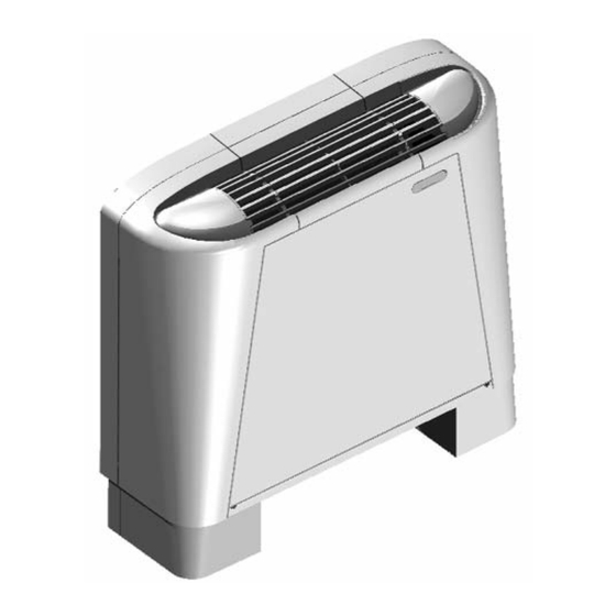
Description of the Appliance
Purpose of the Machine
Available Versions and Installation Methods
General Specifications
Overall Dimensions of Model that Intakes from below
Overall Dimensions of Model that Intakes from the Front
Overall Dimensions of Ducted Model
Overall Dimensions of Bracketing
Main Bank Wet Connections
SUPPLEMENTARY BANK WET CONNECTIONS (Only for 3Row Version)
Key to Wiring Diagrams
Version Vn Motor Wiring
Wiring Diagrams
Installation
Pack and Contents
Safety Regulations
Recommendations for Correct Installation
Operations Prior to Installation
Choice of the Installation Site
Tools Required for Installation
Accessory Parts Normally Available on the Market and Required for Installation
How to Install the Appliance
BANK ROTATION (Only for 3Row Version)
Electrical Connections
HOW to TURN the ELECTRICAL COMPONENTS (Only for 3Row Version)
Operation
How to Operate the Convector Fan
Routine Maintenance
General Recommendations for Cleaning
How to Clean the Exterior Part of the Appliance
How to Clean the Air Filter
How to Drain out the Condensation
Motor
Troubleshooting
Assistance and Spares
Assisance and Spares
Technical Data Plate
Advertisement
Quick Links
1
Table of Contents
2
Description of the Appliance
3
Electrical Connections
4
How to Operate the Convector Fan
5
Troubleshooting
6
Technical Data Plate
Download this manual
TOP FAN PLUS
Fan coil
INSTALLATION AND OPERATION MANUAL
EN
Table of
Contents
Previous
Page
Next
Page
1
2
3
4
5
Advertisement
Table of Contents
Need help?
Do you have a question about the 15 and is the answer not in the manual?
Ask a question
Questions and answers
Related Manuals for Ferroli 15
Air Conditioner Ferroli VTP 15 Installation Manual
Fan coil for wall application (36 pages)
Boiler Ferroli ENERGY TOP W 70 Instructions For Use, Installation And Maintenance
Wall-mounted (160 pages)
Boiler Ferroli TEMPRA 30 Installation, Service And User Instructions Manual
Copper wall-mounted system, gas fi red boiler for central heating, fan assisted, room sealed compartment, electronic fl ame ignition and control (48 pages)
Boiler Ferroli Econcept 50 A Installation And Operating Instructions Manual
Wall-hung, pre-mix gas- fired condensing boiler (34 pages)
Boiler Ferroli ECONCEPT 100 Instructions For Use, Installation And Maintenance
Premixed gas-fired heat generator with condensation (32 pages)
Gas Heater Ferroli ECONCEPT 100 Instructions For Use, Installation And Maintenance
Heat generator running on gas, pre-mixed with condensation (28 pages)
Fan Ferroli 120 Installation And Operation Manual
Top fan plus (28 pages)
Fan Ferroli TOP FAN Technical Bulletin
Fan coil (52 pages)
Fan Ferroli TOP FAN Plus rem Installation Manual
Fan coil (24 pages)
Fan Ferroli MERCURY ST Series Instructions For Installation, Use And Maintenance Manual
Ducted fan coil (36 pages)
Fan Ferroli JOLLY Plus 2 User Manual
Tangential fan coil units with brushless motors (36 pages)
Fan Ferroli JOLLY Plus 2 VERSIONE VM-F Installation Manual
Tangential fan coil units with brushless motos (52 pages)
Fan Ferroli MERCURY 2 Installation And Operation Manual
(48 pages)
Fan Ferroli Rem I User Manual
Fan coil for wall application (28 pages)
This manual is also suitable for:
20
30
40
50
60
80
...
Show all
100
120
Table of Contents
Print
Rename the bookmark
Delete bookmark?
Delete from my manuals?
Login
Sign In
OR
Sign in with Facebook
Sign in with Google
Upload manual
Upload from disk
Upload from URL


Need help?
Do you have a question about the 15 and is the answer not in the manual?
Questions and answers