Table of Contents
Advertisement
Quick Links
Advertisement
Table of Contents

Related Manuals for Martin Cyclo 03 Directional


Summary of Contents for Martin Cyclo 03 Directional
- Page 1 Cyclo 03 Directional user manual...
- Page 2 © 2004 Martin Professional A/S, Denmark. All rights reserved. No part of this manual may be reproduced, in any form or by any means, with- out permission in writing from Martin Professional A/S, Denmark. Printed in Denmark. P/N 35000163, Rev B...
-
Page 3: Table Of Contents
......... 30 Cyclo 03 Directional Specifications... -
Page 5: Introduction
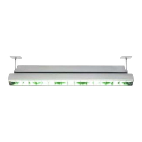
Introduction Thank you for selecting the Martin Cyclo 03 Directional. The Cyclo 03 Directional is a dynamic fluorescent color changing luminaire that can be programmed for stand-alone operation or controlled via DMX. The Cyclo 03 Directional is designed for dynamic color illumination of walls and surfaces. - Page 6 • Provide a minimum clearance of 0.1 meters (4 inches) around the luminaire. • Do not modify the luminaire or install other than genuine Martin parts. • Do not operate the luminaire if the ambient temperature (Ta) exceeds 40° C (104° F).
-
Page 7: Installation
Work from a stable platform and block access below the work area when installing or servicing luminaires above head-height. Lighting track mounting The Cyclo 03 Directional can be mounted on lighting track from all major manufacturers (Nokia, Erco, Zumtobel, iGuzzini, Nordic Aluminium, etc.) Installation... - Page 8 A 3mm Allen key is required for this operation. To mount a Cyclo 03 Directional on lighting track: 1. Isolate the lighting track from the power supply and ensure that power cannot be reapplied, even accidentally. 2. Hold the luminaire up to the lighting track and slide the ends of the mounting arms into the slot in the track.
- Page 9 Surface mounting The Cyclo 03 Directional can be surface-mounted on a floor, wall or ceiling using a bracket kit that is available as an accessory. To surface-mount the Cyclo 03 Directional: 1. Ensure that the surface on which you want to mount the Cyclo 03...
-
Page 10: Ac Power
20mA. Connecting to mains power Cyclo 03 Directional luminaires have an ENSTO male connector built into the casing for mains power input. A female ENSTO connector is supplied with the luminaire for installation on the power supply cable. - Page 11 • The terminal marked the neutral wire. The following connectors and cables are available from your Martin dealer: ENSTO 3-pole 16A/250V male connector ... P/N 05347202 ENSTO 3-pole 16A/250V female connector ..P/N 05327202 ENSTO male/female cable (15 cm/5.9in.).
-
Page 12: Data Linking Multiple Luminaires
32 luminaires or 500 meters, or to add branches, an optically isolated amplifier-splitter such as the Martin RS-485 Opto-Splitter (P/N 90758060) must be used. Data cable can be connected to the Cyclo 03 Directional via RJ-45 sockets that are wired as follows: • pins 7 & 8 to ground (earth) •... -
Page 13: Burning In Fluorescent Tubes
91613028) in the RJ-45 data output of the last luminaire. 4. If using a DMX control device, use suitable cable to connect the device’s DMX output to one of the RJ-45 sockets on the first Cyclo 03 Directional. TIp! Random “flicker” and other unexplained control problems... -
Page 14: Stand-Alone Operation
Stand-alone operation In stand-alone operation, the Cyclo 03 Directional can be used without a DMX controller. Static single colors or two-color mixes can be displayed, or luminaires can be programmed to change colors in cycles. Changes can be programmed at 1, 5, 10 or 30 second intervals. -
Page 15: Stand-Alone Operation Settings
A quick reference table covering DIP switch functions is also provided on the back cover of this manual. S t a n d - a l o n e o p e r a t i o n s e t t i n g s Activating colors DIP switch pins 1 to 3 each activate a color in the stand-alone program. -
Page 16: Single Stand-Alone Operation
M a s t e r / s l a v e s t a n d - a l o n e o p e r a t i o n Important! Do not set more than one luminaire on a data link as master, and do not set a luminaire as master on a data link with a DMX Cyclo 03 Directional user manual... - Page 17 More sophisticated light shows can be programmed using a DMX controller (see “DMX controlled operation” on page 21). The synchronization signal used by the Cyclo 03 Directional is identical to that used in other 3-tube Cyclo luminaires, allowing these products to be combined in master/slave operation on one data link.
- Page 18 Fade to 50% and back to 100% in one scene (applies when only one color is active and crossfading is selected) Example 1 DIP switch 7 is set to ON (crossfading) and only red is activated: Scene Cyclo 03 Directional user manual...
- Page 19 Example 2 DIP switch 7 is set to OFF (blackout fading) and only red is activated: Scene Example 3 DIP switch 7 is set to ON (crossfading) and red and blue are activated: Blue Scene Example 4 DIP switch 7 is set to OFF (blackout fading) and red and blue are activated: Blue Scene Example 5...
- Page 20 4. When power is applied, slave luminaires will go to the next scene in their program each time the master goes to its next scene. Slave luminaires will also start scene 1 of their programs each time the master starts scene 1 of its program. Cyclo 03 Directional user manual...
-
Page 21: Dmx Controlled Operation
Connect a data cable to the DMX control device’s data output and one of the Cyclo 03 Directional’s RJ-45 DMX sockets. If your control device has an XLR data output socket, you may need to buy or wire an XLR-to-RJ45 converter. - Page 22 Address Calculator at http://www.martin.dk/service/utilities/AddrCalc/index.asp (see illustration below). 3. You can also look up DIP-switch settings using the Martin DIP Switch Calculator, available for use and downloadable at http://www.martin.dk/service/dipswitchpopup.htm If you do not have Internet access, refer to "Table 2: DIP switch address settings"...
- Page 23 Find the address in the table. Read the settings for pins 1 - 5 to the left and read the settings for pins 6 - 9 above the address. “0” means OFF and “1” means ON. Pin 10 is always OFF for DMX operation. For example, to set the DMX address to 101, you need to set DIP-switch pins 1, 3, 6 and 7 to ON.
-
Page 24: Controlling Via Dmx
The color temperature of white light can also be fine-tuned. Depending on the functions available on the controller, sophisticated light shows on the Cyclo 03 Directional can be programmed over time, allowing constantly and rapidly shifting color mixes, or color displays which change slowly according to the time of day, or even year, for example. -
Page 25: Service
Service With long-life fluorescent tubes and no moving parts, the Cyclo 03 Directional is almost service-free. F l u o r e s c e n t t u b e r e p l a c e m e n t The Osram high output T5 tubes fitted as standard meet color specifications for at least 10 000 hours, after which color intensity may gradually fall. - Page 26 If the reflector is difficult to move by pulling, insert a small screwdriver between the reflector and the housing, next to the second fin from the end, to help release the clip. Cyclo 03 Directional user manual...
- Page 27 4. The diffuser is held in place by metal clips at each end of the luminaire. Push a clip back and remove the diffuser. You now have access to the tubes. 5. Pressing on the metal caps at both ends of the tube, rotate the tube 1/4 turn in whichever direction is easiest, and slide the tube’s terminal pins out of...
-
Page 28: Cleaning
Tube positions Tube positions in the Cyclo 03 Directional are identified as follows: Marking in Marking on luminaire tube Reference illustration OSRAM FQ 54W/60 RED OSRAM FQ 54W/66 GREEN OSRAM FQ 54W/67 BLUE R G B The burning positions of fluorescent tubes affect their operating temperature, light output and tube life. -
Page 29: Troubleshooting
Troubleshooting Problem Probable cause(s) Remedy No response from fixture when In stand-alone mode, DIP Set DIP switch pin 8 to OFF to power is applied. switch pin 8 set to ON (pause). resume stand-alone program. No power to luminaire. Check power connections. No power to lighting track. -
Page 30: Dmx Protocol
Intensity 1 100% 253-255 Intensity 100% Green intensity Tube off → 3-252 1 - 99 Intensity 1 100% 253-255 Intensity 100% Blue intensity Tube off → 3-252 1 - 99 Intensity 1 100% 253-255 Intensity 100% Cyclo 03 Directional user manual... -
Page 31: Cyclo 03 Directional Specifications
Cyclo 03 Directional Specifications P H Y S I C A L L x W x H (with mounting arms) ....1200 x 107 x 285 mm (47.3 x 4.2 x 11.2 in.) L x W x H (without mounting arms) . - Page 32 Cyclo 03 Directional, titanium ..... P/N 90550055 Cyclo 03 Directional, white ..... . . P/N 90550050...
- Page 36 7. ON = Crossfading OFF = Blackout fading 5/6. Program speed Quick reference Cyclo 03 Directional DIP switch settings www.martin-architectural.com • Olof Palmes Allé 18 • 8200 Aarhus N • Denmark Tel: +45 8740 0000 • Fax +45 8740 0010...
Need help?
Do you have a question about the Cyclo 03 Directional and is the answer not in the manual?
Questions and answers