Table of Contents
Advertisement
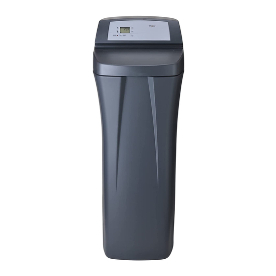
Model WHESFC
How to install, operate
and maintain your
Water Conditioner
Do not return system to store
If you have any questions or concerns when
installing, operating or maintaining your water
conditioner, call our toll free number:
1-866-986-3223
Monday- Friday, 8 AM - 7 PM EST or visit
www.whirlpoolwatersofteners.com
When you call, please be prepared to provide
the model and serial number of your product,
found on the rating decal, typically located on
the rim below the salt lid hinges.
System tested and certified by NSF International
against NSF/ANSI Standard 42 for the reduction
of chlorine taste and odor, and Standard 44
for hardness reduction and efficiency,
and certified to NSF/ANSI Standard 372.
Manufactured and warranted by
Ecodyne Water Systems
1890 Woodlane Drive
Woodbury, MN 55125
7346075 (Rev. B 3/27/15)
Advertisement
Table of Contents

Related Manuals for Whirlpool WHESFC


Summary of Contents for Whirlpool WHESFC
- Page 1 Model WHESFC How to install, operate and maintain your Water Conditioner Do not return system to store If you have any questions or concerns when installing, operating or maintaining your water conditioner, call our toll free number: 1-866-986-3223 Monday- Friday, 8 AM - 7 PM EST or visit www.whirlpoolwatersofteners.com...
-
Page 2: Table Of Contents
TABLE OF CONTENTS Page Specifications & Performance Claims ............3 Water Conditioner Safety . -
Page 3: Specifications & Performance Claims
Specifications & Performance Claims SPECIFICATIONS Model WHESFC Model Code LLFC 11,000 @ 2.6 lbs. Rated Softening Capacity (Grains @ Salt Dose) 24,700 @ 7.8 lbs. 31,100 @ 13.4 lbs. Rated Efficiency (Grains/Pound of Salt @ Minimum Salt Dose) 4,230 @ 2.6 lbs. -
Page 4: Water Conditioner Safety
Water Conditioner Safety Your safety and the safety of others are very important. We have provided many safety messages in this manual and on your appliance. Always read and obey all safety messages. This is the safety alert symbol. This symbol alerts you to potential hazards that can kill or hurt you and others. All safety messages will follow the safety alert symbol and either the word “DANGER”... -
Page 5: Inspect Shipment
Inspect Shipment The parts required to assemble and install the water Remove and discard (or recycle) all packing materials. conditioner are included with the unit. Thoroughly To avoid loss of small parts, we suggest you keep the check the water conditioner for possible shipping dam- small parts in the parts bag until you are ready to use age and parts loss. -
Page 6: Installation Requirements
Installation Requirements LOCATION REQUIREMENTS PLUMBING CODES Consider all of the following when selecting an installa- All plumbing must be completed in accordance with tion location for the water conditioner. national, state and local plumbing codes. = Do not locate the water conditioner where freezing In the state of Massachusetts: The Commonwealth temperatures occur. -
Page 7: Installation Requirements
Installation Requirements VALVE DRAIN REQUIREMENTS 1/4” NPT Thread Barbs for 3/8” Using the flexible drain hose (included), measure and I.D. Tubing cut to the length needed. Flexible drain hose is not Hose Clamp allowed in all localities (check your plumbing codes). If local codes do not allow use of a flexible drain hose, a Drain Hose rigid valve drain run must be used. -
Page 8: Dimensions
Dimensions 19” 3-3/4” 18” IN – OUT 47-7/8” 41-1/2” 39-1/2” FIG. 8 Installation Instructions TYPICAL INSTALLATION Hard Water Conditioned Water To Outside Faucets Pipe Clips Water Conditioner 1” NPT Sweat Valve Adaptor (not included) 1” NPT Controller Threaded Adaptor Outlet Plug-in O-ring Power... - Page 9 Installation Instructions TURN OFF WATER SUPPLY Nozzle Top Cover Venturi Brine Tank 1. Close the main water supply valve, located near the Assembly Overflow well pump or water meter. Elbow Nut - 2. Open all faucets to drain all water from house pipes. Ferrule NOTE: Be sure not to drain water from the water Salt...
- Page 10 Installation Instructions COMPLETE INLET AND OUTLET PLUMBING Measure, cut, and loosely assemble pipe and fittings from the main water pipe to the inlet and outlet ports of the water conditioner valve. Be sure to keep fittings fully together, and pipes squared and straight. Be sure hard water supply pipe goes to the water condi- Electrical Shock Hazard tioner valve inlet side.
- Page 11 Installation Instructions ADD WATER AND SALT TO THE SALT RINSE OUT CARBON FINES STORAGE TANK Small particles of carbon filtration material are generat- ed during manufacturing and shipping, which will exit the media tank with the first water flow. These carbon “fines”...
- Page 12 Installation Instructions SANITIZE THE WATER CONDITIONER / TEST FOR LEAKS SANITIZE AFTER SERVICE To prevent air pressure in the water conditioner and plumbing system, complete the following steps in 1. Slide open the salt lid, remove the brinewell cover order: and pour about 90 ml (6 tablespoons) of household bleach into the conditioner brinewell.
-
Page 13: Programming The Water Conditioner
This is a reminder to use 1. Press the UP or DOWN buttons to set the Whirlpool WHE-WSC Water Softener Cleanser ® present time. Up moves the display ahead; down three times a year. To reset the timer, press any sets the time back. -
Page 14: Programming The Water Conditioner
Programming the Water Conditioner SET WATER HARDNESS NUMBER Salt Type allows you to choose between sodium chlo- ride (NaCl), which is regular softener salt, or potassi- 1. Press the PROGRAM button once again to display um chloride (KCl), which is an alternative to sodium a flashing “25”... -
Page 15: Customizing Features / Options
Customizing Features / Options RECHARGE SET SALT LEVEL The RECHARGE button is used to initiate an immedi- The water conditioner has a salt monitor indicator ate recharge. light to remind you to add salt to the storage tank. 1. Press and hold the RECHARGE button until the NOTE: You must set salt level each time salt is added words “RECHARGE", “SERVICE"... - Page 16 Customizing Features / Options SALT EFFICIENCY CLEAN / CLEAR WATER IRON REDUCTION This feature is beneficial on water supplies containing When this feature is ON, the water conditioner will operate at salt efficiencies of 4000 grains of hardness ferrous (clear water) iron. The default setting is OFF. per pound of salt or higher (May recharge more often When this feature is set to ON, an additional back- using smaller salt dosage and less water).
- Page 17 Customizing Features / Options CLEANSING FEATURE 1. Press and hold the PROGRAM button until the screen in Figure 29 is displayed. Once in this dis- The cleansing feature keeps larger particles of sedi- play, press the PROGRAM button four times and ment from entering the home’s plumbing system.
-
Page 18: Routine Maintenance
Lift the brinewell cover and pour in the entire 16 oz. cold water faucet immediately downstream of the con- bottle of Whirlpool Water Softener Cleanser. Press ® ditioner until water tastes, smells and appears normal. - Page 19 Routine Maintenance ADDING SALT CLEANING THE NOZZLE & VENTURI Lift the salt lid and check the salt storage level fre- A clean nozzle & venturi (See Figure 34) is a necessity quently. If the water conditioner uses all the salt for the water conditioner to work properly.
-
Page 20: Troubleshooting
Troubleshooting AUTOMATIC ELECTRONIC DIAGNOSTICS 3. Symbols in the display indicate POSITION switch operation (See Figure 36). This water conditioner has a self-diagnostic function for the electrical system (except input power and/or water meter). The water conditioner monitors elec- tronic components and circuits for correct operation. If a malfunction occurs, an error code appears in the display. - Page 21 Troubleshooting RESETTING TO FACTORY DEFAULTS 2. After observing fill, press the RECHARGE button to move the conditioner’s valve into the brine position. To reset the electronic controller to its factory default A slow flow of water to the drain will begin. Verify for all settings (time, hardness, etc.): brine draw from the brine tank by shining a flash- light into the brinewell and observing a noticeable...
-
Page 22: Exploded View & Parts List
Conditioner Exploded View Valve Assembly See Pages 24 & 25 for parts... - Page 23 Conditioner Parts List Part No. Description Part No. Description Distributor O-Ring Kit 7332131 Salt Lid (order decal below) – 7112963 (includes Key Nos. 1-3) 7336622 Instruction Decal O-Ring, 2-7/8” x 3-1/4” 7305257 O-Ring, 13/16” x 1-1/16” 7335901 Cover, Brinewell O-Ring, 2-3/4” x 3” Brinewell Assembly 7137824 7077870...
- Page 24 Valve Exploded View wear-strip seal cross-section view...
- Page 25 Valve Parts List Part No. Description Part No. Description 7224087 Screw, #8-32 x 1” (2 req.) 7337597 O-Ring, 1-1/16” x 1-5/16”, pack of 4 Turbine & Support Assembly, 7286039 Motor (incl. 2 ea. of Key No. 100) – 7290931 including 2 O-Rings (See Key No. 7231393 Motor Plate 123) &...
-
Page 26: Warranty
This warranty applies to consumer-owned installations only. ® / TM © 2014 Whirlpool. All rights reserved. Manufactured under license by Ecodyne Water Systems, Woodbury, Minnesota.
Need help?
Do you have a question about the WHESFC and is the answer not in the manual?
Questions and answers