Table of Contents
Advertisement
Quick Links
RETURN TO MAIN MENU
IM937
®
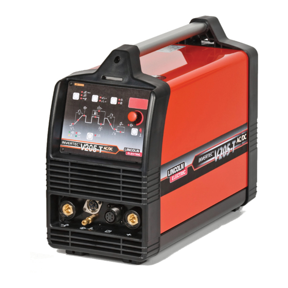
INVERTEC V205-T DC & V205-T AC/DC TIG
April, 2007
11426, 11430
For use with machines having Code Numbers:
Safety Depends on You
Lincoln arc welding and cutting
equipment is designed and built
with safety in mind. However, your
overall safety can be increased by
proper installation ... and thought-
ful operation on your part. DO
NOT INSTALL, OPERATE OR
REPAIR THIS EQUIPMENT
WITHOUT
READING
THIS
MANUAL AND THE SAFETY
PRECAUTIONS CONTAINED
THROUGHOUT. And, most
importantly, think before you act
and be careful.
OPERATOR'S MANUAL
Copyright © 2007 Lincoln Global Inc.
• World's Leader in Welding and Cutting Products •
• Sales and Service through Subsidiaries and Distributors Worldwide •
Cleveland, Ohio 44117-1199 U.S.A. TEL: 216.481.8100 FAX: 216.486.1751 WEB SITE: www.lincolnelectric.com
Advertisement
Table of Contents

Related Manuals for Lincoln Electric 205-TAC/DCTIG


Summary of Contents for Lincoln Electric 205-TAC/DCTIG
- Page 1 RETURN TO MAIN MENU IM937 ® INVERTEC V205-T DC & V205-T AC/DC TIG April, 2007 11426, 11430 For use with machines having Code Numbers: Safety Depends on You Lincoln arc welding and cutting equipment is designed and built with safety in mind. However, your overall safety can be increased by proper installation ...
-
Page 2: California Proposition 65 Warnings
351040, Miami, Florida 33135 or CSA Standard W117.2-1974. A Free copy of “Arc Welding Safety” booklet E205 is available from the Lincoln Electric Company, 22801 St. Clair Avenue, Cleveland, Ohio 44117-1199. BE SURE THAT ALL INSTALLATION, OPERATION, MAINTENANCE AND REPAIR PROCEDURES ARE PERFORMED ONLY BY QUALIFIED INDIVIDUALS. -
Page 3: Electric Shock Can Kill
ELECTRIC SHOCK can kill. 3.a. The electrode and work (or ground) circuits are electrically “hot” when the welder is on. Do not touch these “hot” parts with your bare skin or wet clothing. Wear dry, hole-free gloves to insulate hands. 3.b. - Page 4 WELDING and CUTTING SPARKS can cause fire or explosion. 6.a. Remove fire hazards from the welding area. If this is not possible, cover them to prevent the welding sparks from starting a fire. Remember that welding materials from welding can easily go through small cracks and openings to adjacent areas.
- Page 5 PRÉCAUTIONS DE SÛRETÉ Pour votre propre protection lire et observer toutes les instructions et les précautions de sûreté specifiques qui parraissent dans ce manuel aussi bien que les précautions de sûreté générales suiv- antes: Sûreté Pour Soudage A LʼArc 1. Protegez-vous contre la secousse électrique: a.
- Page 6 SAFETY EN 60974-10 V205-T DC & V205-T AC/DC TIG...
- Page 7 SAFETY EN 60974-10: V205-T DC & V205-T AC/DC TIG...
- Page 8 Electric for advice or information about their use of our products. We respond to our customers based on the best information in our posses- sion at that time. Lincoln Electric is not in a position to warrant or guarantee such advice, and assumes no liability, with respect to such infor- mation or advice.
-
Page 9: Table Of Contents
viii Installation...Section A Technical Specifications ...A-1 Select Suitable Location ...A-2 Stacking...A-2 Tilting ...A-2 Environmental Area ...A-2 Machine Grounding and High Frequency Interference Protection ...A-2 Input Connections ...A-3 Reconnect Procedure...A-3 230V Input ...A-4 115V Input ...A-4 Attachment Plug Installation, Engine Driven Generator ...A-4 Output Connections...A-5 Output and Gas Connection for Tig Welding...A-5 Work Cable Connection ...A-5... -
Page 10: Installation
TECHNICAL SPECIFICATIONS - V205-T DC TIG K2629-1 (Code Number 11426) Input Voltages * / 50 /60 Hz. Duty Cycle (115V) 35% 100% (115V) 40% 100% (230V) 35% 100% (230V) 40% 100% Output Current Range 6-200 Amps RECOMMENDED INPUT WIRE AND FUSE SIZES FOR MAXIMUM RATED OUTPUT INPUT VOLTAGE / FREQUENCY (HZ) -
Page 11: Select Suitable Location
Read entire installation section before starting installation. Safety Precautions WARNING ELECTRIC SHOCK can kill. • Only qualified personnel should per- form this installation. • Turn the input power OFF and unplug the machine from the recep- tacle before working on this equip- ment. -
Page 12: Input Connections
3. Be sure the torch and work cable rubber cover- ings are free of cuts and cracks that allow high frequency leakage. Cables with high natural rub- ber content, such as Lincoln Stable-Arc resist high frequency leakage than neoprene and other synthetic rubber insulated cables. -
Page 13: 230V Input
230V INPUT The equipment is provided with a 230/115V cable, 6.6ft.(2m) in length with a 230V 6-50P attachment plug. The Invertec V205-T performs best when connected to 230VAC inputs. This input allows full output of the machine (200 amps). 115V INPUT A suitable 115V attachment plug must be installed on the power cord to use the V205-T with a 115V input supply. -
Page 14: Output Connections
This unit does not include a TIG torch, but one may be purchased separately. The accessories section of this manual lists a number of Lincoln Electric TIG torches, and TIG Torch Starter Packs that are recommended for use with this machine; however, any similar TIG torch can be used. -
Page 15: Quick Disconnect Plug
QUICK DISCONNECT PLUG (FOR STICK ELEC- TRODE CABLE and WORK CABLE) A quick disconnect system is used for the welding cable connections. The stick electrode cable will need to have a plug attached. 1. Cut off welding cable lug, if present. 2. -
Page 16: Operation
Read and understand this entire section before operating your machine. SAFETY INSTRUCTIONS WARNING ELECTRIC SHOCK can kill. • Do not touch electrically live parts such as output terminals, electrode or internal wiring. • Insulate yourself from the work and ground. •... -
Page 17: Rear Control Panel
REAR CONTROL PANEL • I1: Off/On switch turns on the electric power to ------------------------------------------------------------------------ * With "l1" in the "I" (ON) position, the welding machine is operational and there is voltage between the positive (+) and negative (-) Terminals in stick welding. -
Page 18: Controls And Settings
CONTROLS AND SETTINGS All operator controls and adjustments are located on the case front of the V205-T machine. Refer to Figure B.2 and the corresponding explanations. VDR OFF VDR ON 1. Input Voltage warning light green LED - Indicates that the machine is on and input voltage is within acceptable range. - Page 19 6. Digital Display - displays currently set values for each mode or welding parameter. 7. Local/Remote push button - Selects the welding current adjusting system: • from front panel • from remote control The LED beside the symbol confirms the selection. 8.
-
Page 20: Welding Parameter Defaults And Ranges
4. Release the TIG torch trigger. The output current of the machine will turn OFF and the gas valve will remain open to continue the flow of the shielding gas. The duration of this postflow time is adjusted by the Postflow parameter. This operation is shown in (4 step diagram 1). -
Page 21: Set Up Menu
SET UP MENU Many additional parameters can be modified via the Set Up Menu. To access the Set Up Menu: • Position the ON/OFF switch to OFF “0”. • Depress and hold the Parameter select Push Button. • Position the On/Off switch to on "I" at the back of the machine;... -
Page 22: Output Limitations
OUTPUT LIMITATIONS The maximum output current as specified in the instal- lation section of this manual is derated in several situ- ations; alternate AC Wave Forms, elevated AC Frequencies and 115V input. • Alternate AC Wave Forms (See Set Up Menu)¹ Square 200 amps max. -
Page 23: Dc Electrode Positive Polarity
DC Electrode Positive Polarity. (Direct Current Reverse Polarity) (see Figure B.5) In this case, there is a continuous flow of electrons from the workpiece to the electrode. The reverse polarity is used for welding alloys covered with a layer of refractory oxide. With this polarity the electrode functions as anode and is subjected to a high degree of heat;... -
Page 24: Steel Tig Welding
STEEL TIG WELDING The TIG process is very effective for welding both car- bon steel and alloy steel, especially in applications requiring precision results. DC Electrode Negative Polarity is required. Since this process does not include the removal of impurities, proper cleaning and preparation of the edges is required. - Page 25 B-10 PROTECTIVE GAS Both argon and helium work when welding aluminum. Argon is preferred, due to its lower cost and consump- tion rate. This gas also tends to stabilize the arc, thus making it easy to operate. For some applications, however, the use of helium, or argon-helium blends, is recommended due to better weld penetration and faster travel speed.
-
Page 26: Ac Tig Welding Quick Start Up
B-11 AC TIG WELDING QUICK START UP (AC/DC model only) WARNING ELECTRIC SHOCK can kill. • Have an electrician install and service this equipment. • Turn the input power off at the fuse box, dis- connect or unplug supply lines and allow machine to sit for five minutes minimum to allow the power capacitors to discharge before working inside this equipment. -
Page 27: Dc Tig Welding Quick Start Up
B-12 DC TIG WELDING QUICK START UP WARNING ELECTRIC SHOCK can kill. • Have an electrician install and service this equipment. • Turn the input power off at the fuse box, dis- connect or unplug supply lines and allow machine to sit for five minutes minimum to allow the power capacitors to discharge before working inside this equipment. -
Page 28: Factory Installed
OPTIONAL ACCESSORIES AND COMPATIBLE EQUIPMENT Factory Installed Twist-Mate Cable Connectors 1 – standard for Ground Clamp 1 – Gas Pass through for Tig Torch Strap Packet Instruction Manual Field Installed K857 - Remote Output Control - For Stick welding. When the V205-Tʼs Output Control is in the "REMOTE"... -
Page 29: Maintenance
SAFETY PRECAUTIONS ELECTRIC SHOCK • Have an electrician install and ser- vice this equipment. • Turn the input power off at the fuse box, disconnect or unplug supply lines and allow machine to sit for five minutes minimum to allow the power capacitors to dis- charge before working inside this equipment. -
Page 30: How To Use Troubleshooting Guide
HOW TO USE TROUBLESHOOTING GUIDE Service and Repair should only be performed by Lincoln Electric Factory Trained Personnel. Unauthorized repairs performed on this equipment may result in danger to the technician and machine operator and will invalidate your factory warranty. For your safety and to avoid Electrical Shock, please observe all safety notes and precautions detailed throughout this manual. - Page 31 Observe all Safety Guidelines detailed throughout this manual PROBLEMS (SYMPTOMS) PROBLEMS IN STICK WELDING Excessive spatter Craters Inclusions Insufficient penetration Sticking Porosity Cracks If for any reason you do not understand the test procedures or are unable to perform the tests/repairs safely, contact your TROUBLESHOOTING POSSIBLE CAUSE...
- Page 32 Observe all Safety Guidelines detailed throughout this manual PROBLEMS (SYMPTOMS) PROBLEMS IN TIG WELDING Oxidation Tungsten inclusions Porosity Hot cracking If for any reason you do not understand the test procedures or are unable to perform the tests/repairs safely, contact your TROUBLESHOOTING POSSIBLE CAUSE...
-
Page 33: Electrical Failures
PLAY" • Welding circuit Inductance too high. 6. E20, E24, or E25 Flashing on "DIGITAL DISPLAY" • Internal memory errors. (Contact your local Lincoln Electric Authorized Service Facility.) CAUTION V205-T DC & V205-T AC/DC TIG RECOMMENDED COURSE OF ACTION If all recommended possible areas of... -
Page 34: Wiring Diagrams
WIRING DIAGRAMS V205-T DC & V205-T AC/DC TIG... -
Page 35: Wiring Diagram
WIRING DIAGRAM V205-T DC & V205-T AC/DC TIG... - Page 36 NOTES V205-T DC & V205-T AC/DC TIG...
- Page 37 NOTES V205-T DC & V205-T AC/DC TIG...
- Page 38 ● WARNING ● Spanish ● AVISO DE PRECAUCION ● French ● ATTENTION ● ● German WARNUNG ● Portuguese ● ATENÇÃO ● Japanese Chinese Korean Arabic ● ● ● ● ● ● ● ● ● ●...
- Page 39 ● ● ● ● ● ● ● ● ● ● ● ● ● ● ● ● ● ● Spanish ● PRECAUCION French ● ATTENTION ● German WARNUNG Portuguese ● ● Japanese Chinese Korean Arabic WARNING AVISO DE ATENÇÃO...
- Page 40 • World's Leader in Welding and Cutting Products • • Sales and Service through Subsidiaries and Distributors Worldwide • Cleveland, Ohio 44117-1199 U.S.A. TEL: 216.481.8100 FAX: 216.486.1751 WEB SITE: www.lincolnelectric.com...
Need help?
Do you have a question about the 205-TAC/DCTIG and is the answer not in the manual?
Questions and answers