Simrad AP28 Operator's Manual
Autopilot
Hide thumbs
Also See for AP28:
- Installation manual (54 pages) ,
- Installation manual (32 pages) ,
- Installation manual (28 pages)
Table of Contents
Advertisement
Quick Links
Advertisement
Table of Contents

Related Manuals for Simrad AP28


Summary of Contents for Simrad AP28
- Page 1 OPERATOR MANUAL AP28 AUTOPILOT 20222527 / A Sw.1.1 English...
-
Page 2: About This Manual
First issue Rev. A This manual is intended as a reference guide for operating and maintaining the Simrad AP28 autopilot. An autopilot is a complex control system so please take time to read this manual to get a thorough understanding of the operation, the system components and their relationship to a complete AP28 autopilot system. -
Page 3: Table Of Contents
2.4 Standby mode ........16 2.5 Automatic steering ......... 17 2.6 NoDrift mode......... 36 2.7 Navigating with the AP28 ......37 2.8 Wind vane steering (sailboats) ....41 2.9 Wind steering and navigation (sailboats) ... 45 2.10 Data pages.......... 48 2.11 Multiple station system ...... - Page 4 7.1 General ..........115 7.2 Control unit ......... 115 7.3 Autopilot Computer ......115 7.4 Rudder Feedback ......... 115 7.5 Compass..........116 7.6 Drive unit ........... 116 7.7 Exchange of software program ....116 8 Optional equipment ........ 117 4 | AP28 Manual...
- Page 5 8.1 R3000X Remote Control (NFU) ....117 8.2 S35 Steering Lever (NFU)...... 118 8.3 JS10 Joystick (NFU)......118 8.4 AP28 with MSD50 Stern Drive unit..118 9 Glossary..........121 10 Index ............ 125 AP28 Manual | 5...
- Page 6 Blank page 6 | AP28 Manual...
-
Page 7: System Description
30 and 50 feet with a host of features. The autopilot system can be expanded and enhanced with a selection of options and accessories. The brain in the AP28 autopilot system is the single "intelligent" autopilot computer that communicates on the proprietary SimNet data and control network to... -
Page 8: System Components
(SimNet cable without terminator) Multijoiner Non SimNet RF25 Rudder Feedback SimNet Figure 1-1 AP28 Basic system layout 1.3 AP28 Control Unit A compact autopilot control for panel, bulkhead or bracket mounting. A multifunction LCD display with two-color backlighting presents readout of autopilot and navigation... -
Page 9: Autopilot Computer
Multiple control units can be added to the system by daisy-chaining or drop cable to the SimNet network. 1.4 Autopilot Computer The autopilot computer is the main unit in the AP28 autopilot system. It contains the steering computer and drive electronics for the drive unit motor and clutch and provides interface to other system components. -
Page 10: Heading Sensors
1.6 Heading Sensors RC42 Rate Compass RC42 is a fluxgate compass with an integrated rate of turn sensor. It provides a significant improvement to the dynamic performance of both the autopilot and a stabilized radar display. A 5 m (16 feet) SimNet cable with connector is attached. -
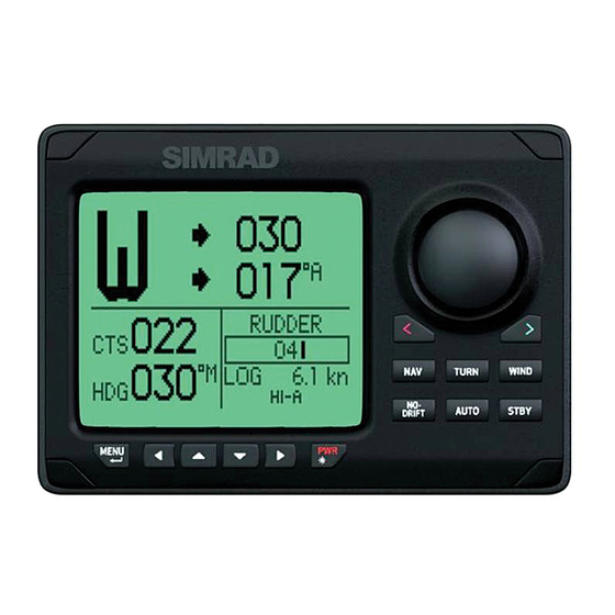
Page 11: Operation
• Verify at regular intervals course and position of vessel • Always switch to Standby mode and reduce speed in due time to avoid hazardous situations 2.1 Overview Figure 2-1 AP28 Front Panel Operation | 11... - Page 12 Description Power ON-OFF / Light key Standby key STBY Engage Standby mode Auto key AUTO Engage Auto mode NoDrift key DRIFT Engage NoDrift mode Nav key Engage NAV mode Wind key WIND Engage Wind mode Turn key TURN Enter turn sub-menu Tack or gybe in Wind mode Menu/Enter key MENU...
- Page 13 Port key Adjust the commanded course or wind angle 1 or 10 degrees Enable port power steering Action according to the softkey symbol Starboard key Adjust the commanded course or wind angle 1 or 10 degrees Enable starboard power steering Action according to the softkey symbol Softkeys When the basic operation of the keys is...
-
Page 14: On/Off
WIND mode. Each mode provides you with a multifunction mode display. User adjustable settings are found in the AP28 Main Menu (page 51). Alarms Alarms are presented in plain text to alert you of system and external data failure conditions. -
Page 15: Backlighting
• Product name • Software version and release date Software version and release date are examples only. After approximately 5 seconds, the system is operative and the unit that was turned on will show the Standby mode display. Other units in a multistation system will display . -
Page 16: Standby Mode
The Up/Down softkeys to increase/decrease the light level by one step The Day/Night softkey to toggle between day and night profiles If no adjustment is performed within 3 seconds, the Light level overlay window will close. For contrast and day/night settings, refer to page 60. 2.4 Standby mode STBY mode is the mode that is used when steering the boat at the helm. -
Page 17: Automatic Steering
2.5 Automatic steering AUTO (Compass) mode When the AUTO key is pressed, the AP28 automatically selects the current boat heading as the set course and maintains the rudder angle. This gives a bumpless transfer at the mode change. -
Page 18: Heading Capture
The AP28 will keep the boat on the set course until a new mode is selected or a new course is set with the course knob or the PORT or STBD keys. One revolution of the course knob equals a 45° course change. -
Page 19: Control Of Steering Performance
Dodging The AP28 has no specific dodge key. Simply press STBY and power steer or use the helm to pass any obstacle. When you return to AUTO mode within 60 seconds the following display is shown, offering two alternatives: Go back to AUTO mode... - Page 20 Speed Transition to LO parameters with increasing speed: 10 Knots Transition Speed set to 9 Knots Transition to HI parameters with decreasing speed: 8 Knots Display legend HI-A High response parameters set automatically LO-A Low response parameters set automatically HI-M High response parameters set manually LO-M Low response parameter set manually...
- Page 21 Response adjust The Autotune function in the AP28 is so refined that the majority of boats will need no further adjustments of the steering parameters. On some boats, however, or at particular sea conditions a fine tuning of the steering parameters may improve the performance of the autopilot.
- Page 22 Range Change per step Default Wind response (sailboats) Verify that the difference between Course To Steer (CTS) and the actual heading is at an acceptable minimum. If the difference between the set wind angle and the actual wind angle is too big, increase the ‘Wind response’ to reduce the difference.
- Page 23 Selection of HI/LO parameters MENU The “Manual select” item has three alternatives: Auto – HI – LO. • Auto is automatically set by speed input • HI or LO must be set manually when there is no speed input The sub-headline in the display shows the active parameter set and how it is selected.
- Page 24 U-Turn U-Turn changes the current set course to be 180 degrees in the opposite direction. This feature is very useful in a man overboard situation and whenever you want to steer back on a reciprocal heading. TURN Press either the key to select the direction to make the U-Turn and start the turn.
- Page 25 TURN Press the key to select the direction in which to make the C-turn and start. The turn rate (ROT) can be adjusted before the turn is initiated and during the turn. Increasing the turn rate yields to a smaller circle and vice versa. MENU Turn Change per...
- Page 26 Spiral-turn The spiral-turn feature may also be used for circling fish or when searching a particular object on the seabed. Spiral-turn makes the boat turn in a spiral with a decreasing or increasing radius. To enter Spiral-turn mode: TURN The “initial” radius can be set before the turn is started. Press either the key to select the direction in which to make the spiral-turn and start.
- Page 27 MENU Negative values indicate decreasing radius while positive values indicate increasing radius. Increasing radius Decreasing radius Change Turn parameter Range Default per step 33 ft - 3281 ft 164 ft Initial radius 10 m - 1000 m 50 m Change of radius -164 ft - +164 ft 66 ft per turn...
- Page 28 Zigzag-turns To enter zigzag-turn mode: TURN The course change can be set before the turn is initiated (2-70°). Press either the key to select the direction in which to make the first course change and start. While sailing in a zigzag pattern you can alter the course change, leg distance, and the main course.
- Page 29 Initial course change 20° Main course Course change 40° Leg distance Change Turn parameter Range Default per step Course change 4° - 140° 28° 82 ft - 9843 ft 1641 ft Leg distance 25 m - 3000 m 500 m The unit for leg distance is the same as the unit set for depth (feet or meter).
- Page 30 You can at any time change the main course. You can also at any time change the distance of the leg until the boat makes a new 90° turn. MENU Change Turn parameter Range Default per step 82 ft - 9843 ft 1641 ft Leg distance 25 m –...
-
Page 31: Lazy S-Turn
Lazy S-turn To enter Lazy S-turn mode: TURN The course change can be adjusted before the turn is initiated (2-80°). Press either the key to select the direction in which to make the first course change and start. While in a Lazy S pattern you can alter the course change magnitude, turn radius and the main (average) course. - Page 32 Adjust course change and radius as follows: MENU Initial course change Main course Course change Higher radius Main course Lower radius Change Turn parameter Range Default per step Course change 4° - 160° 28° 16 ft - 1641 ft 164 ft Radius 5 m –...
- Page 33 Depth Contour Tracking, DCT With input from an echo sounder, the autopilot can be set to steer the boat to a set depth. This is very useful if you want to follow a depth contour. Make sure you have depth reading available in the system. Smooth seabed Rocky waters Slope...
-
Page 34: Depth Gain
The actual depth reading is shown on the display. Steer the boat to the depth you want to track and in the direction of the depth contour (main course). When the wanted depth is shown in the display, activate the depth contour steering with the softkey (any of the two). - Page 35 Contour Cross Angle (CCA) With this parameter you can make the boat lazy s across your reference depth. With the CCA set to zero there is no S-ing. The CCA is an angle that is added to or subtracted from the set course. Each time the boat crosses the reference depth, the sign (+/-) of the CCA is changed and makes the boat turn to cross the reference depth contour in the opposite direction.
-
Page 36: Nodrift Mode
Tacking in Auto mode (sailboat) The tack function is only available when the system is set up for SAIL boat type in the installation setup. Tacking in AUTO mode is different from tacking in WIND mode. In AUTO mode the tack angle is fixed and can be set in the Setup/Sailing menu. -
Page 37: Navigating With The Ap28
The information received from the navigator automatically changes the course to steer to keep the boat on the track line and direct the AP28 to the destination waypoint. If the AP28 is connected to a navigation receiver that does not transmit a message with bearing to next waypoint, it will steer on Cross Track Error (XTE) only. - Page 38 Position source (GPS/Chart plotter) see page 57. Navigational steering should only be used in open waters. When selecting NAV mode, the AP28 maintains the current set course and prompts the user to accept the course change towards the destination waypoint.
- Page 39 GPS/chart plotter. Three decimals give a more accurate track keeping. When operating the AP28 in NAV mode to steer through a route of waypoints, the AP28 will steer to the nearest waypoint in the direction of the route after you accept the NAV mode prompt.
- Page 40 Setting the waypoint arrival circle For route navigation it is recommended to use automatic waypoint shift at a set waypoint arrival circle. The arrival circle should be adjusted according to boat speed. The higher the speed, the wider the circle. The intention is to make the autopilot start the heading change in due time to make a smooth turn onto the next leg.
-
Page 41: Wind Vane Steering (Sailboats)
Selecting a different navigation source If you have more than one navigator connected to the AP28, you will be able to choose any for navigation. Refer to the ‘Sources’ item in the Setup menu for details on how to select a different navigator (page 58). - Page 42 Adjustments to the set wind angle is as per below. Steer port Steer stbd Adjust set wind angle Major wind angle adjust 1°/ push CCW: Steer port CW: Steer stbd Regain manual steering by pressing the STBY key. STBY Tacking in Wind mode Tacking in WIND mode as compared to AUTO mode can be performed when sailing with apparent or true wind as the reference;...
- Page 43 TURN Gybing Gybing is possible when the true wind angle is larger than 120°. TURN The time to make a gybe is determined by the speed of the boat to make it as quick as possible within control. Tack and gybe prevent When beating and running, using the autopilot is most critical.
- Page 44 reduces the boat speed. Hence the boat will be more difficult to steer because the rudder will become less effective. The tack prevent function in WIND mode has been implemented to avoid such situations. It will react immediately when the apparent wind angle becomes 5° less than the set minimum wind angle, and more rudder will be commanded.
- Page 45 Blank page Operation | 45...
-
Page 46: Wind Steering And Navigation (Sailboats)
2.9 Wind steering and navigation (sailboats) The autopilot can also steer the boat given both wind data and track data from a GPS/chart plotter. In this mode called WIND mode the automatic steering is based on a set of criteria (see below). Wind steering and navigation is activated by pressing the NAV key when in Wind mode [1]. - Page 47 8. You are on the last leg directly to the waypoint. The autopilot is now keeping the boat on track (XTE) and displays bearing and distance to the waypoint. Figure 2-2 Operation | 47...
-
Page 48: Data
2.10 Data pages A number of data pages can be displayed if the information is available on SimNet (see page 109). When one of the main mode pages are displayed, access and scroll through the available data pages by pressing the Up/Down keys. -
Page 49: Multiple Station System
Main mode screen 2.11 Multiple station system In normal operation control is accessible from every control unit connected to the AP28 system. One control unit is "active" and provides the user with access to all functions. All remaining control units are "inactive"... - Page 50 Blank page 50 | Operation...
-
Page 51: Main Menu
Calibrate Offset Rudder feedback Max stbd/port Set rudder 0 Boat type Virtual feedback Rudder drive SimNet config SimNet groups Instance number Service SimNet status System data Resets Autopilot reset Global reset Demo About AP28 Remote lock Main menu | 51... -
Page 52: Data Pages Setup
The main menu is activated by a press on the MENU key. The main menu items give further access to sub menus and parameter settings. Parameter settings are usually presented to the right, but may also be listed in an overlay window. Language settings presented Unit settings presented in in an overlay window. - Page 53 Disabling pages Continue to select pages and repeat the procedure if more pages are to be disabled. Press and hold the Left key to leave the menu and return to last active page. Enabling pages A disabled page is only visible when using the Enable/disable command.
-
Page 54: Setup Menu
Restore all pages To restore all disabled data pages, select Restore data pages: 3.2 Setup menu The Setup menu contains items that the user may want to use on a less regular basis. The following items are described: Changing the damping factors Alarm setup Automatic and manual source selection Changing the display settings... - Page 55 Damping The damping factor indicates how fast the display will respond to changes. The higher the damping factor the more stable display reading on the instrument. Damping of the apparent wind angle is made by the Advanced Wind Filter (AWF) in the Autopilot Computer. Increasing the ‘Wind damping’, will make the AWF output depend more on heading and boat speed.
-
Page 56: Shallow Water
Alarms The AP28 may be set up to sound an alarm if vessel or environmental parameters exceeds preferred values. The alarm monitoring is disabled by setting the value to Off. Shallow water The setting of the alarm is global and can be made on any Simrad unit that has this function implemented. - Page 57 Range Change per step Default Off, 5-90° Alarm status Displays a list of present alarms Sources A data source can be a sensor or a device connected to SimNet providing data to other SimNet devices. Data can be of different type such as compass data, apparent wind data, calculated wind data, depth data, etc.
- Page 58 Automatic source update The Auto select function is mainly for situations where the automatic source selection needs to be updated because a selected data source is not supplying data or has been physically replaced with another one. The update secures that the existing source selections are valid and maintained.
- Page 59 See information about the selected data source. For data types which can be calibrated, an overlay screen displaying the data from the selected data source will appear first (Ref. Installation/Calibration). Enter the Calibrate and Offset menu. (Ref. Installation/Calibration). Proceed to display a list of available sources for the given data type.
- Page 60 The profiles are Day profile and Night profile. The profiles can be optimized for readability under different light conditions, and you can quickly switch between the two using the PWR key and the softkeys. Refer to Backlighting, page 15. Display contrast The contrast controls the difference between the text/graphics and the display background.
- Page 61 Setting Range Change per step Default Light level Off – 9 White (Day) Light color White/red Red (Night) Invert Yes/No display Language The language is set when the autopilot is turned on for the first time. Refer First time turn on, page 69. It is however possible to change the language at any time.
- Page 62 Units of measure Parameter Options Default Boat speed − kn − km/h − mph Wind speed − kn − m/s − mph Distance − nm − km − mi Depth − m − ft Heading − °M °M − °T Temperature −...
- Page 63 Seastate filter The Seastate filter is used to reduce rudder activity and autopilot sensitivity in rough weather. OFF: Seastate filter is disabled. This is default. AUTO: Reduces rudder activity and autopilot sensitivity in rough weather by an adaptive process. The AUTO setting is recommended if you want to use the seastate filter.
- Page 64 Tack time When performing a tack in WIND mode, the rate of turn (tack time) can be adjusted. This will give single-handed sailors time to handle the boat and the sails during a tack. A turn performed without shifting wind side, will also be made at a controlled turn rate.
- Page 65 Range Default Auto – Apparent - True Auto VMG optimizing Optimizing the VMG to wind will be active for 5–10 minutes after a new wind angle has been set and only when beating. ‘VMG’ will be displayed below the mode index when the VMG optimizing feature is active.
-
Page 66: Remote Lock
3.3 Remote lock The "Remote lock" function is a safety feature included in the AP28 system. It will disable all other control units. When the "Remote lock" function is in use, no transfer of command can take place; only the active control unit stays in command. - Page 67 • The active control unit unlocks the other ones and makes them inactive: • The system is switched OFF by any control unit (press PWR key for 2-3 seconds). Main menu | 67...
- Page 68 Blank page 68 | Main menu...
-
Page 69: Setup At Installation
Installation Setup, the hardware installation and electrical connections must be completed in accordance with the installation instructions. When the AP28 is powered on for the first time, the instrument will run through an automatic start-up sequence presenting: Product name, software version, release date... -
Page 70: Installation Menu
4.2 Installation Menu The installation settings must be performed as part of the commissioning of the AP28 system. Failure to do so correctly may prohibit the AP28 from functioning properly! The Installation menu can only be accessed in STBY mode. -
Page 71: Dockside Settings
Commissioning Dockside settings If the autopilot has no rudder feedback unit installed refer to Virtual Rudder Feedback on page 80-83. The following menu items are accessible and can be set up in the Dockside menu: Boat type Rudder feedback Virtual feedback Drive voltage Drive engage Rudder test... -
Page 72: Rudder Feedback Calibration
Select appropriate Boat type by using the Up and Down keys. Confirm by pressing the softkey. Rudder feedback calibration Make sure the unit is installed and aligned as per instruction in the AC12/42 Installation manual. The rudder feedback calibration will set the correct relationship between the physical rudder movement and the rudder angle readout. - Page 73 MENU Confirm Rudder feedback calibration to starboard by pressing the MENU key. Manually turn the helm/wheel to port until the rudder stops at port lock (H.O.). Adjust the displayed angle the same way as for starboard rudder. MENU Confirm Rudder feedback calibration to port by pressing the MENU key.
- Page 74 Special test of LF3000/LFI3000 Mk2 feedback Align engines to center position; “zero rudder”. Rev engines to 3-4000 rev/min and observe the rudder angle indicator on the autopilot, a 2° change in the reading should be accepted. If the rudder angle exceeds 2°, connect the screen on the TB1 cable (LFI3000) to the center block terminal and repeat item 2 (Refer to the AC12/AC42 Installation manual).
-
Page 75: Drive Engage
Hence, the voltage to the solenoids will be the same as the supply voltage. During the Rudder Test, the AP28 system will automatically detect whether the drive unit is a reversible motor or a solenoid is operated. - Page 76 Clutch: This is the default setting and it allows you to steer the boat with the helm or wheel when in STBY mode. The port will activate (go high) in all active steering modes, and typically engage a bypass valve on a hydraulic linear drive or a clutch on a mechanical drive.
-
Page 77: Depth Calibration
Depth calibration This adjustment only applies to “smart” depth transducers that outputs depth on NMEA2000 format. The default value for the depth offset is 0.0, which indicates the displayed depth from the transducer to the seabed (b). Refer to the illustration on next page. The value should be increased or decreased, depending on whether the depth reading should be from the water line or from the keel respectively:... - Page 78 The symbol in front of the depth reading will change to indicate that the depth is measured from: the keel line the water Range Step Default value Units -10 - +10 0 – ±5: 0.1 m, ft 5 – 10: 0.5 Press the MENU key to confirm the offset setting.
- Page 79 Steer to wind Wind steering is only available if ‘Boat type’ is set to ‘Sail’ in the Installation menu. The ‘Minimum wind angle’ is the minimum apparent wind angle that will keep the sails well shaped and give an acceptable thrust. This parameter will vary from boat to boat.
- Page 80 Range Change per step Default Units 10 - 30 ° Dockside settings when using Virtual Rudder Feedback The Virtual Feedback algorithms in the autopilot software enable your autopilot to steer without a conventional rudder feedback unit. These algorithms are designed for vessels up to 40 ft.
-
Page 81: Boat Type
Select “Dockside” menu and press the softkey to confirm. Boat type When the autopilot is configured for Virtual Feedback the Boat type is automatically set to Outboard. Virtual Feedback calibration The Virtual feedback calibration is entered as a numerical value equal to the physical rudder angle observed at the hard over position. - Page 82 Rudder test To perform the Virtual Feedback rudder test you must be able to view the movement of the engines/drives (“rudder”). Activate the automatic rudder test as shown, following the instructions on the display. Confirm by pressing the softkey. The next step is to enter the correct direction of the rudder movement.
- Page 83 Proceed as per display instructions and immediately release the key when the rudder reaches the port hard over position. The rudder will now be automatically centered. The Rudder test is verified by the display showing ‘Motor OK’ or ‘Failed’. If ‘Failed’ is given, check for correct electrical connection.
-
Page 84: Set Rudder Zero
Seatrial settings The Seatrial menu presents settings and automatic calibrations to be performed during seatrial. The seatrial must always be performed in open waters at a safe distance from other traffic. The Seatrial menu can only be accessed if the Dockside Settings are completed and confirmed. -
Page 85: Compass Calibration
Set the trim tabs and stabilizers to have no effect on the boat’s heading. Steer the boat manually on a steady course. If required, confirm the rudder ZERO position by pressing the softkey. Compass calibration Before the compass calibration is started, make sure that there is enough open water around the vessel to make a full turn. - Page 86 See illustration next page. Calibration is made on the compass that is active for the autopilot. If another model compass from Simrad or another manufacturer is installed, refer to the instruction for that compass regarding calibration. 86 | Setup at installation...
- Page 87 Lubber line Lubber line Magnitude of local field in % of earth’s magnetic field. Direction of local field with respect to lubber line. It can also be on the reciprocal. In certain areas and at high latitudes the local magnetic interference becomes more significant and heading errors exceeding ±3°...
- Page 88 Wind Calibration This calibration only applies if you have a wind transducer directly connected to SimNet (IS12TW) or a wind transducer that outputs data on NMEA2000 format. Any residual error in the apparent wind angle display can be corrected manually by entering the required offset. A positive value indicates starboard offset angle,- a negative value indicates port offset angle.
- Page 89 0.01 1.00 Transition speed The transition speed is the speed at which the AP28 will automatically change the steering parameter set from HI to LO parameters, or vice versa (page 19). The default setting of the transition speed is 6 knots.
-
Page 90: Automatic Tuning
Dockside menu. Automatic tuning is a procedure that is not required for the AP28 to function as it is preset with steering parameters that should steer most boats in the 30-50 foot range. It is, however, recommended to perform an automatic turning as part of the seatrial. -
Page 91: Commissioning Status
The parameter values calculated during Autotune becomes the HI parameters. The LO parameters are automatically set to 66% of the HI. After the Autotune has been completed the rudder must be controlled manually, as the autopilot has returned to STBY mode. The Automatic tuning function will take control of the boat and perform a number of S-turns. - Page 92 Return to the Installation menu item ‘Automatic steering’ if you want to adjust the steering parameters. See below for information. Automatic steering The Automatic steering menu contains steering parameters for course steering, wind steering and nav steering. Recall autotuned To recall the parameter values that were achieved during the Autotune procedure, select Recall autotuned under ‘Automatic Steering’, and press the key.
- Page 93 • LO value parameters for automatic steering at high speed and when sailing into the wind or reaching with a sailboat Confirm by pressing the softkey. Boat type Own boat Displayed Displacem. Planing & parameter Autotune Manual & Sail Outboard Rudder HI 0.50 0.30...
- Page 94 Rudder sets the rudder gain which is the ratio between the commanded angle and the heading error. Course to steer Too little Rudder Course to steer Too much rudder • Too little Rudder and the autopilot fails to keep a steady course •...
-
Page 95: Minimum Rudder
New course Counter rudder setting too high, sluggish and creeping response New course Correct setting of counter rudder, ideal response Autotrim standard value is 40 seconds which should work well on most boats. On boats operating on VRF it should be set to 20 seconds Rate Limit should be kept at 6.0°/second unless there is a need for more rapid response in turns. - Page 96 • Set waypoints into each navigator connected to the system, and verify that the AP28 steers in NAV mode for each NAV source • Try the NoDrift mode •...
- Page 97 • If the rudder response feels aggressive during the seatrial, you may want to reduce the rudder speed to get a smoother steering. Alternatively on a sailboat you may want to have a higher rudder speed when running • The motor Drive out (page 98) can be set with the above in mind.
- Page 98 • Locating the Mains circuit breaker and the separate SimNet circuit breaker if provided Calibration The Calibration is another entry to procedures for calibrating the compass, rudder feedback, depth, apparent wind angle and boat speed. These procedures are covered under ‘Commissioning’. Rudder drive The sub-menu items linked under ‘Rudder drive’...
- Page 99 If the auto-setting does not perform properly due to high inertia from the wheel or a loose steering gear, it can be adjusted manually. Find the lowest possible value that will prevent the rudder from continuous hunting. A wide deadband will cause inaccurate steering.
-
Page 100: Simnet Groups
Simrad, None, 1-6 Simrad Alarms Simrad, None, 1-6 Simrad Simrad: Default group for AP28 None: Not assigned to a group 1 – 6: Group numbers The figures on next page illustrates how the instruments on a flybridge and in a cockpit are assigned to separate language, damping and backlight groups, and how this affects the setup for the different instruments. - Page 101 LANGUAGE = FLYBRIDGE NONE DISPLAY = 1 DAMPING = 1 COCKPIT DISPLAY = 2 Setup at installation | 101...
-
Page 102: Service Information
The instance number is used to identify multiple units of the same model when connected to a SimNet or NMEA2000 network. The instance number is added to the product name e.g. AP28-1, AP28-2 for easy identification of the unit. Range... - Page 103 Confirm Demo mode by pressing the softkey. If the unit is turned off while in demo mode, the demo mode will still be active on next power on. Demo mode is deactivated by using the menu as illustrated above. The user will be notified with a ‘DEMO’...
- Page 104 Blank page 104 | Setup at installation...
-
Page 105: Alarm System
5 Alarm system 5.1 Alarm indication The alarm system in the AP28 autopilot is activated if any alarm settings are exceeded. Refer to Alarms, page 56. When an alarm is notified, the alarm will be indicated with an alarm text and with an audible alarm. -
Page 106: Acknowledging An Alarm
5.2 Acknowledging an alarm An alarm is acknowledged by pressing any key. This will remove the alarm notification (text, light and sound) from all units that belongs to the same alarm group. Refer to SimNet Groups, page 100. A reminder will reappear at given intervals as long as the alarm situation exists. - Page 107 Alarm ID Alarm Shallow water Deep water Anchor alarm Wind shift alarm True wind speed too high True wind speed too low Boat speed too low Voltage too high Voltage too low Depth data missing Wind data missing Navigation data missing Compass data missing Off course Rudder feedback data missing...
- Page 108 Blank page 108 | IS20 Alarm system...
-
Page 109: Troubleshooting
6 Troubleshooting An autopilot is a complex system. Its performance depends on a proper installation and a successful seatrial. The main menu includes a Service item that access several options to display data used when testing or troubleshooting the system. 6.1 SimNet status The SimNet status screen provides you with status information about the different SimNet messages used by... -
Page 110: Resets
In the event an Autopilot reset has been made, refer to chapter 4.2. Global reset A Global reset resets the entire SimNet setup in the Simrad Group and initiates a new automatic interface setup. See chapter 4.1. To confirm the Global reset press the softkey. The display will prompt you to repeat the interface setup. -
Page 111: Alarms
Autopilot failures In the event of an autopilot failure, the AP28’s numerous test features will assist you in isolating a probable fault. Audible and visual alarm are provided for every fault being detected, see chapter 5. Refer to the table below for hints and try to solve the problem yourself. - Page 112 Display Probable fault Recommended action readout Shallow water The depth is inside the set Carefully observe the actual limit or outside the range depth Depth data is missing Adjust the alarm limit if not hazardous Steer to safe depth, the alarm will reset automatically Turn off the shallow alarm if data is missing...
- Page 113 Display Probable fault Recommended action readout Rudder test Following conditions may Refer to recommended actions failed exist: for the specific probable faults Rudder feedback failure Autopilot Computer current overload Bypass/clutch overload Rudder moves in only one Check the connections direction Replace the autopilot computer Poor connection to one of the solenoids (continuously...
- Page 114 Display Probable fault Recommended action readout Bypass/clutch Clutch/bypass current Check actual current overload exceeds 3.3 Amps (overload Check voltage marking on coil or short circuit) Check coil resistance (through connecting wires) Bypass/clutch Poor connection or open Check connections disengaged circuit in bypass/clutch coil Replace bypass/clutch if open Perform new "Rudder test"...
-
Page 115: Maintenance
7 Maintenance 7.1 General The AP28 units are “repair by replacement” units, and the operator is therefore required to perform only a very limited amount of preventive maintenance. 7.2 Control unit The AP28 Control Unit will under normal use require little maintenance. -
Page 116: Compass
If the compass is exposed to the weather, make a visual inspection at 2-3 months intervals, and at the start of each season. 7.6 Drive unit Refer to the drive unit manual for maintenance instructions. 7.7 Exchange of software program Contact Simrad Customer Support about software updates. 116 | Maintenance... -
Page 117: Optional Equipment
If you keep the key pressed, it modes are will automatically change the active when the setting in increments of 3° per lamp is lit. second. Simrad R3000X Mode changes are as per table below. Initial press press mode NAV and WIND... -
Page 118: S35 Steering Lever (Nfu)
JS10 has no mode change feature. The rudder will move for as long as the lever is held in left (Port) or right (Starboard) position. 8.4 AP28 with MSD50 Stern Drive unit The information in this chapter only applies if your autopilot is driving a Simrad MSD50 Stern Drive. - Page 119 Zero point setting Unless you need a rudder angle display when leaving the dock, just steer the boat manually on a straight course and press the AUTO key. The zero point is then set automatically. If you prefer to use the rudder angle display when leaving the dock, proceed as follows: After turn-on the rudder angle display will alternate between 10...
- Page 120 Blank page 120 | Optional equipment...
-
Page 121: Glossary
9 Glossary Apparent wind – The speed and direction from which the wind appears to blow with reference to the bow when the boat is moving (also called relative wind). Arrival alarm – An alarm signal issued by a GPS/chart plotter that indicates arrival at or at a predetermined distance from a waypoint (see arrival circle). - Page 122 NMEA0183 sentences, e.g. XTE. Product ID – A number, suffix, acronym or term that can identify a product. Product name – The name of a Simrad product known from sales and other literature. Route - A stored sequence of waypoints. These waypoints will be listed in the order in which you desire to follow them.
- Page 123 Simrad Group, Class 2 products will automatically subordinate themselves to the Class 1 source selection. SimNet Group – A number of Simrad products that are selecting and sharing the same data sources via the SimNet network. SimNet Source – Any product or device directly connected to SimNet or NMEA2000, or interfaced to SimNet via NMEA0183 or Robnet2.
- Page 124 Blank page Glossary | 124...
-
Page 125: Index
10 Index about AP28, 103 damping, 55 alarm data pages, 48 codes, 107 data pages setup, 53 indication, 105 day profile, 60 listing, 111 demo mode, 102 shallow water, 56 depth calibration, 77 wind shift, 56 depth contour tracking, 33... - Page 126 motor output, 98 configuration, 99 groups, 100 multiple station, 49 instance number, 102 status, 109 software program, 116 nav change limit, 39, 79 version, 10 navigating, 38 sources, 57 NFU Steering lever, 118 speed over ground, 89 night profile, 60 spiral-turn, 26 NoDrift, 36 square-turn, 29...
Need help?
Do you have a question about the AP28 and is the answer not in the manual?
Questions and answers