Table of Contents
Advertisement
Advertisement
Table of Contents
Troubleshooting

Related Manuals for PGO BR-500


Summary of Contents for PGO BR-500
- Page 2 INDEX OF TOPICS TIME CHART...
-
Page 3: Preface Of Standard Operating Time Scale
6.If the parts repaired are not in the table , please find the nearest one to represent the repairing time. Motive Power Industry CO., LTD April,2007 P.12-2 PGO BR-500 ENGINE... -
Page 4: Parts List
AIR CLEANER ASSY FOR TK ªÅ®ðÂo²M¾¹²Õ¦X 0417 CARBURETTOR ASSY ¤Æªo¾¹Á`¦¨ 0418 MOTOR COMP. STARTER °_°Ê°¨¹F²Õ¦X 0419 INTAKE MANIFOLD ¶i®ðª[ºÞ 0420 COVER,SECOND AIR ªÅ®ð¶i®ð»\ 0421 SECOND AIR PIPE COMP ¶i®ð¾ÉºÞ²Õ¦X 0422 AIAC COMP ªÅ®ð¾É¤J±±¨î»Ö²Õ¦X 0423 INJECTOR ¼Qªo¼L 0424 THROTTLE BODY ¸`¬y»ÖÅé P.12-3 PGO BR-500 ENGINE... - Page 5 CYLINDER ASSY ¨T¬û²Õ¦X 0617 PISTON ASSY ¬¡¶ë²Õ¦X 0618 CRANKSHAFT COMP ¦±¬`¶bÁ`¦¨ 0619 ENGINE OIL ¤ÞÀº¾÷ªo 0620 OIL SEAL, LH CRANKSHAFT ¥ª¦±¬`¶bªo«Ê 0621 OIL SEAL, RH CRANKSHAFT ¥k¦±¬`¶bªo«Ê 0622 OIL COOLER COMP ¾÷ªo§N«o¾¹²Õ¦X 0623 COUNTERSHAFT COMP ¥-¿Å¶b P.12-4 PGO BR-500 ENGINE...
- Page 6 ³QÅX°Ê-±¥Ö±a½ü²Õ¦X 1219 TRANSMISSION COVER CASE ¶Ç°Ê½c»\ 1220 DRIVE SHAFT ÅX°Ê¶b 1221 FINAL GEAR ASSY ³Ì²×¾¦½ü²Õ¦X 1222 0.25 GEAR OIL ¾¦½üªo 1223 MUFFLER ASSY.(OR FRONT SECTION) ®ø-µ¾¹Á`¦¨(©Î«e¬q) 1224 MUFFLER REAR SECTION ®ø-µ¾¹«á¬q 1225 HEAT PROTECTOR, MUFFLER ®ø-µ¾¹Å@ªO P.12-5 PGO BR-500 ENGINE...
- Page 7 GASKET WATER PUMP ¤ô¬¦¹Ô¤ù 2012 SHAFT WATER PUMP ¤ô¬¦¼Ï¶b 2013 HOSE A,B WATER §N«o¤ôºÞ A,B 2014 THERMOSTAT ASSY «í·Å¾¹ 2015 COVER THERMOSTAT «í·Å¾¹»\ 2016 EARTH TERMINAL THERMO «í·Å¾¹®y 2017 THERMO UNIT ASSY ¦Û°Ê±±·Å¾¹ 2018 BY-PASS VALVE ®Ç³q»Ö P.12-6 PGO BR-500 ENGINE...
- Page 8 REVERSE GEAR BOX COMP -ËÀɾ¦½ü½cÁ`¦¨ B0116 BEARING, REVERSE GEAR BOX -ËÀɾ¦½ü½c¶b©Ó B0117 REVERSE CABLE -ËÀɾɽu B0118 HAND PARKING CABLE ¤â·Ù¨®¾É½u B0119 DRIVING SHAFT(CV JOINT) ¶Ç°Ê¶b B0120 DIFFERENTIAL CABLE ®t³t¾É½u B0121 SOLENDID VALVE CABLE ¹qºÏ»Ö¾É½u B0122 DIFFERENTIAL SHIFTING LEVER ®t³t§â¤â P.12-7 PGO BR-500 ENGINE...
- Page 9 BRAKE PAD SET (FRONT OR REAR) ·Ù¨®¤ù²Õ¦X(«e©Î«á) B0215 ªoÀ£«b¨®ºÞ(«e©Î«á) HOSE , HYDRAULIC BRAKE (FRONT OR REAR) B0216 PROTECTIVE COVER, DRIVING CHAIN Áå±ø«OÅ@»\ B0217 ¾÷±ñ·Ù¨®§¨Á`¦¨(«e©Î«á) PARK CALIPER COMP. (FRONT OR REAR) B0218 PADS OF PARK CALIPER ·Ù¨®¶ô(¾÷±ñ·Ù¨®§¨) P.12-8 PGO BR-500 ENGINE...
- Page 10 B0313 THROTTLE CABLE ¥[ªo¾É½uÁ`¦¨ B0314 INDUCT MAGNETO ·PÀ³ºÏÅK B0315 REAR MIRROR ASSY. «áµøÃèÁ`¦¨ 0.05 B0316 BRACKET 2, COUNTER INDUCT -p¼Æ¾¹·PÀ³©T©wªO2 B0317 BRACKET 1, COUNTER INDUCT -p¼Æ¾¹·PÀ³©T©wªO1 B0318 BRAKE SAFETY SWITCH ·Ù¨®¦w¥þ¶}Ãö B0319 BRAKE ADJUSTING PIN ¾É½u½Õ¾ã¶b¾P P.12-9 PGO BR-500 ENGINE...
- Page 11 ¤UÄa¦QÁ×¾_Ũ®M B0415 SWING ARM ASSEMBLY, UPPER ¤W·nÁu B0416 SWING ARM ASSEMBLY, LOWER ¤U·nÁu B0417 BUSH, SWING ARM ·nÁuŨ®M B0418 CONNECTING ROD(LH OR RH) ©Ô±ì, ¤W·nÁu(¥ª©Î¥k) B0419 GREASE VALVE ª`ªo»Ö 0.05 B0420 CUSHION BUSH, SWING ARM ·nÁu®MºÞŨ¹Ô P.12-10 PGO BR-500 ENGINE...
- Page 12 0.05 B0522 LICENSE LAMP COMP µP·Ó¿OÁ`¦¨ B0523 FRT SIGNAL LAMP ASSY (LH OR RH) «e¤è¦V¿O²Õ¦X(¥ª©Î¥k) B0524 REAR SIGNAL LAMP ASSY(LH OR RH) «á¤è¦V¿O²Õ¦X(¥ª©Î¥k) 0.05 B0525 RELAY Ä~¹q¾¹ B0526 SOLENDID VALVE ¹qºÏ»Ö B0527 3rd BRAKE LAMP ²Ä¤T·Ù¨®¿OÁ`¦¨ P.12-11 PGO BR-500 ENGINE...
- Page 14 INDEX OF TOPICS PRIOR TO DELIVERY...
- Page 18 Failure to suitable charge the battery before its first us at a low electrolyte level will cause an early failure of the battery. Caution: when installing the battery, connect the positive cable before connecting the negative one, and perform the reverse operation upon reoval. P.11-5 PGO BR-500 ENGINE...
- Page 19 Using fuses with inadequate capacity may cause damages to the kart or even cause fire hazards. Level Check: Hydraulic braking system fluid level Rear hub oil level Engine coolant level Engine oil level P.11-6 PGO BR-500 ENGINE...
- Page 20 INDEX OF TOPICS Automatic transmission… … … … … … … … … … … … … … … … … … … . . 1 0 -2 Final reduction… … … … … … … … … . . … … … … … … … … … … … … . . … 1 0 -22 Flywheel cover…...
-
Page 21: Automatic Transmission
- Unscrew the 4 fastening screws shown in the figure to remove the external air conveyor. Remove the External Air Conveyor - Unscrew the 2 fastening screws shown in the figure to remove the conveyor filter. P.10-2 PGO BR-500 ENGINE... - Page 22 -may damage the hexagon obtained on the shaft or break the bush itself. - Remove the six M6 screws. - Remove the four M8 screws. - Remove the transmission cover. - Check that the bearing rotates freely, otherwise replace it. P.10-3 PGO BR-500 ENGINE...
- Page 23 - Check that the roller is free from wear and that it rotates freely. - Remove the fastening screw by a 13-mm wrench. - Remove the roller and the bearing. N.B.: If the roller does not rotate freely, it requires replacement. P.10-4 PGO BR-500 ENGINE...
- Page 24 - Move the belt downwards. - Suitable support the roller contrast and extract the mobile driving half-pulley with the relevant bushing and the rear washer, being careful not to make the rollers come out. P.10-5 PGO BR-500 ENGINE...
- Page 25 - Check that the clutch bell is not worn or damaged. - Measure the clutch bell inside diameter. Standard value: 160.2 Max value: 160.5 mm N.B.: Check the eccentricity measured, 0.2 mm max. - Extract the driven pulley unit with the belt. P.10-6 PGO BR-500 ENGINE...
- Page 26 - Loosen the tool screw and disassemble thedriven pulley unit, clutch, spring with sheath. Specificequipment and tools: Drivenpulley spring compressor: 020444Y 55-mmwrench: 020444Y009 Ring:020444Y010 -Extract the collar using 2 screwdrivers. -Remove the 4 guide pins. - Extract the mobile driven half- pulley. P.10-7 PGO BR-500 ENGINE...
- Page 27 N.B.: If you need to overhaul the bearings on an assembleddriven pulley unit, it is necessary to support the unit by 001467Y002. the bell - Remove the roller bearing by the specific tool, supporting the fixed half-pulley with the bell. Specific equipment and tools: Handle 020376Y Adapter 28x30 mm 020375Y 25-mm guide 020364Y Bell 001467Y002 P.10-8 PGO BR-500 ENGINE...
- Page 28 Punchfor driven pulley roller casing 020478Y Bell001467Y002 - Install a new ball bearing by the specific tool. Specific equipment and tools: Handle 020376Y Adapter 37 mm 020477Y 20-mm guide 020363Y - Insert the snap ring to lock. P.10-9 PGO BR-500 ENGINE...
- Page 29 N.B.: Upon running-in, the masses must exhibit a central contact surface and must not be different from one another. Different conditions may cause the clutch tearing. - Do not open the masses using tools to prevent a variation in the return spring load. P.10-10 PGO BR-500 ENGINE...
- Page 30 Automatic Transmission - Check that the driving belt is not damaged. - Check the belt width. Minimum width: 25 mm Standard width: 26.2 mm P.10-11 PGO BR-500 ENGINE...
- Page 31 24,5 mm Standard diameter: 24,9 mm - Check that the roller contrast plate slide blocks are not damaged. - Check the wear of the roller housings and of the belt contact surfaces on both half- pulleys. P.10-12 PGO BR-500 ENGINE...
- Page 32 - The covered side must rest onto the inside thrust side of the roller container. - Assemble the half-pulley with the roller contrast and the sliding blocks. - Insert the half-pulley on the driving shaft. - Insert the spacer bushing. P.10-13 PGO BR-500 ENGINE...
- Page 33 Automatic Transmission P.10-14 PGO BR-500 ENGINE...
- Page 34 - Tighten the central screw at the prescribed torque. N.B.: Turn the driven and/or driving pulley to properly tension the belt. Tightening torque: Anti-flapping roller screw: 16,7 ~19,6 Nm P.10-15 PGO BR-500 ENGINE...
-
Page 35: Tightening Torque
Specific equipment and tools: 55-mm wrench: 020444Y009 - To facilitate reassembly on the engine, turn the mobile driven pulley and insert the belt onto the smaller diameter. - Insert the driven pulley unit with the belt. P.10-16 PGO BR-500 ENGINE... - Page 36 - Remove the flat washer and the spring washer as shown in the figure. - Insert the nut in the original position (nut side in contact with the spring washer). P.10-17 PGO BR-500 ENGINE...
- Page 37 - Tighten the driving pulley fastening nut at the prescribed torque - Remove the specific tool. Tightening torque: Driven pulley shaft nut: 160 ~175 Nm P.10-18 PGO BR-500 ENGINE...
- Page 38 - Insert the bell and the spacer. Note: due to the high tightening torque, using different wrenches -such as a conventional polygonal bush ?may damage the hexagon obtained on the shaft or break the bush itself. P.10-19 PGO BR-500 ENGINE...
- Page 39 - Insert the flanged nut. - Prepare the dynamometric wrench for LH locking using a machine hexagon wrench. - Tighten the driven pulley shaft fastening nut using a misaligned wrench. Tightening torque: Driven pulley nut: 92 ~ 100 Nm P.10-20 PGO BR-500 ENGINE...
- Page 40 N.B.: Check that the air inlet and the air outlets are totally free. - Insert the outside plastic transmission cover. - Tighten the 4 fastening screws at the prescribed torque. Tightening torque: Outside transmission cover screws: 7~9 Nm P.10-21 PGO BR-500 ENGINE...
- Page 41 Final Reduction LUBRICATE WITH OIL CLEAN CAREFULLY CAUTION: HANDLE WITH CARE LUBRICATE WITH GREASE ALWAYS REPLACE APPLY PRODUCT REFERENCE QUANTITY TORQUE Nm 24~27 15~17 P.10-22 PGO BR-500 ENGINE...
- Page 42 Specific equipment and tools: 15-mm pliers: 001467Y34 or 001467Y014 Bell: 001467Y031 To remove the lay shaft bearing on the engine crankcase, use the special removing tool. Specific equipment and tools: 20-mm pliers: 001467Y006 Bell: 001467Y035 P.10-23 PGO BR-500 ENGINE...
- Page 43 - Pull out the bearing by the specific tool. Specific equipment and tools: Column kit: 020476Y Handle: 020376Y Adapter 37 mm: 020477Y 30-mm guide: 020483Y - Remove the oil guard by a screwdriver. P.10-24 PGO BR-500 ENGINE...
- Page 44 - Remove the snap ring shown in the figure. - Pull out the driven pulley shaft bearing from the engine crankcase using the specific tool. Specific equipment and tools: Handle for punches: 020376Y Adapter 37 - 40 mm: 020358Y 25 mm guide: 020364Y P.10-25 PGO BR-500 ENGINE...
- Page 45 N.B.: Place it with the balls facing the hub (this applies to bearings with plastic cage). Specific equipment and tools: Handle 020376Y Adapter 42x47 mm 020359Y 15-mm guide 020412Y P.10-26 PGO BR-500 ENGINE...
- Page 46 25 mm guide: 020364Y - Heat the crankcase by the thermal gun. Specific equipment and tools: Heater 020151Y - Check that the matching surface exhibits nodeformations. - Check the bearing capacity. Incase of faults, replace the hub cover. P.10-27 PGO BR-500 ENGINE...
- Page 47 - Replace the snap ring - Heat the wheel axle bearing seat from the cover outside. - Insert the wheel axle bearing on the cover by the specific punch until abutment. Specific equipment and tools: Handle 020376Y Adapter 52x55 mm P.10-28 PGO BR-500 ENGINE...
- Page 48 Adapter 52x55 mm 020360Y 20-mm guide 020363Y - Heat the bearing seats on the cover using the thermal gun. - Support the hub cover using the column kit. Specific equipment and tools: Heater 020151Y Column kit 020476Y P.10-29 PGO BR-500 ENGINE...
- Page 49 - Place the 7 fastening screws, tighten them atthe prescribed torque checking the position of the vent pipe sealing bands andof the 3 shorter screws as shown in the figure - Refill with the prescribed oil to the maximumlevel. Tighteningtorque: Hubcover screws: 24 ~ 27 Nm Prescribed oil: TUTELA ZC90 Quantity:~ 250 cc P.10-30 PGO BR-500 ENGINE...
- Page 50 Flywheel Cover LUBRICATE WITH CLEAN CAREFULLY CAUTION: HANDLE WITH CARE LUBRICATE WITH GREASE ALWAYS REPLACE APPLY PRODUCT REFERENCE QUANTITY TORQUe P.10-31 PGO BR-500 ENGINE...
- Page 51 Be careful not to damage the plastic unions. - Unscrew the 6 fixing screws and remove the water pump cover. N.B.: It is possible to remove the pump cover with sleeves, if required. P.10-32 PGO BR-500 ENGINE...
- Page 52 - Loosen the 14 fastening screws. - Remove the flywheel cover with the relevant gasket and the cooling system sleeve support. N.B.: The screws are of 4 different lengths. Note P.10-33 PGO BR-500 ENGINE...
- Page 53 Caution: Remove the cover avoiding any possible interferences between stator androtor. Caution: Be careful to prevent slippage of the by-pass valve and of the relevantspring. - Remove the by-pass and the relevant spring. - Remove the sealing gasket. P.10-34 PGO BR-500 ENGINE...
- Page 54 - Unscrew the 3 fastening screws and remove stator and its wiring. - Unscrew the 2 fastening screws and remove the reed valve support with head. - Remove the blow-by reed valve with the relevant sealing gasket. P.10-35 PGO BR-500 ENGINE...
- Page 55 N.B.: threading clockwise. It is advisable to prevent the shaft rotation by inserting a 12-mm wrench into the drive. - Extract the shaft with the relevant abutment washer. P.10-36 PGO BR-500 ENGINE...
- Page 56 Flywheel Cover - Remove the sealing ring. - Remove the ceramic ring and the relevant gasket. - Remove the sealing ring for the pump shaft lubrication using a suitably shaped tool. P.10-37 PGO BR-500 ENGINE...
- Page 57 Flywheel Cover - Remove the engine oil filling cap/bar and the reference oil cap for the timing. - Remove the minimum oil pressure sensor. P.10-38 PGO BR-500 ENGINE...
- Page 58 2 cables: stiff cables close to the stator and soft cables to the connector. - Check that the winding is placed so as to not interfere with the fastening screw heads. P.10-39 PGO BR-500 ENGINE...
- Page 59 Flywheel Cover P.10-40 PGO BR-500 ENGINE...
- Page 60 Check that plastic impeller is perfectly integral with the metal part. - Check that the water pump cover is free from deformation or cracks. - Check that the sealing O-rings are in good working order. P.10-41 PGO BR-500 ENGINE...
- Page 61 Flywheel Cover - Check that the blow-by circuit reed closes properly. P.10-42 PGO BR-500 ENGINE...
- Page 62 - For the cover case, carefully check all lubrication paths, in particular: - the 3 by-pass ducts. - Oil feeding duct at the water pump shaft connection. - Pump drainage duct. - Oil pressure sensor feeding duct. P.10-43 PGO BR-500 ENGINE...
- Page 63 Tightening torque: Support screws with head: 0.3 ~0.4 Nm - Install a new pump shaft sealing using the specific tool. Install minimum pressure sensor and tighten at the prescribed torque. Tightening torque: Minimum pressure P.10-44 PGO BR-500 ENGINE...
- Page 64 N.B.: The final introduction depth will be determined by the impeller. - Screw the impeller and tighten prescribed torque. Tightening torque: Water pump impeller: 4 ~ 5 Nm P.10-45 PGO BR-500 ENGINE...
- Page 65 Flywheel Cover P.10-46 PGO BR-500 ENGINE...
- Page 66 - Tighten the screw at the prescribed torque. Tightening torque: Blow-by recovery duct fastening screws: 3 ~4 N - Insert the spring and the by- pass piston on the flywheel cover. N.B.: Lubricate the by-pass valve. P.10-47 PGO BR-500 ENGINE...
- Page 67 Flywheel Cover P.10-48 PGO BR-500 ENGINE...
- Page 68 3 shorter ones are in the position shown in the figure. - the longer one is placed under the engine oil filling cap. - the intermediate ones are for the remaining attachments, except for P.10-49 PGO BR-500 ENGINE...
- Page 69 Caution - Failure to observe this regulation can cause irreversible deformation to the O-ring. - Install the water pump cover and tighten the 6 fastening screws at the prescribed torque. Tighteningtorque: Flywheelcover fastening screws: 3 ~4 Nm P.10-50 PGO BR-500 ENGINE...
- Page 70 - Install the pre-filter and the engine oil drainage cap and tighten at the prescribed torque. - Refill the engine with the prescribed oil type. Tightening torques: Oil drainage cap: 24 ~30 Recommended oil: Selenia HI Scooter 4 Tech 5W/40 P.10-51 PGO BR-500 ENGINE...
- Page 71 Flywheel and Start-up LUBRICATE WITH OIL CLEAN CAREFULLY CAUTION: HANDLE WITH CARE LUBRICATE WITH GREASE ALWAYS REPLACE APPLY PRODUCT REFERENCE QUANTITY TORQUE Nm P.10-52 PGO BR-500 ENGINE...
- Page 72 Be careful not to damage the plastic unions. N.B.: This operation may also be carried with flywheel cover assembled. - Loosen the two fastening screws. - Extract the complete starter motor. P.10-53 PGO BR-500 ENGINE...
- Page 73 Specific equipment and tools: Flywheel lock tool 020472Y - Loosen the magneto flywheel fastening nut. - Remove the specific tool and the fastening nut. P.10-54 PGO BR-500 ENGINE...
- Page 74 19-mm bushing, release the magneto flywheel. Specific equipment and tools: Flywheel removing tool 020467Y - Remove the removing tool. - Remove the nut and extract the magneto flywheel with the start-up rim. - Remove the driving shaft key. P.10-55 PGO BR-500 ENGINE...
- Page 75 - The free wheel is coupled to flywheel with high precision; if removal is difficult, use 2 screws as gripping points and as removing tools, if required. P.10-56 PGO BR-500 ENGINE...
- Page 76 - Extract the intermediate gear provided with torque limiter. - Check the integrity of the magnets. - Check that the magnet support cage is free from deformation or cracks. - Check that the flywheel nailing exhibits no loosening. P.10-57 PGO BR-500 ENGINE...
- Page 77 If only the brass is worn, it is possible to replace only the complete start- up rim. In that case, check also the diameter and the surface of the connection on the driving shaft. In case or irregularities, replace the driving shaft. P.10-58 PGO BR-500 ENGINE...
- Page 78 The limiter assembly cannot be overhauled. Incase of irregularities on the toothed discs, replace the assembly. P.10-59 PGO BR-500 ENGINE...
- Page 79 13 ~15 Nm - Lubricate the free wheel "rollers" - Lubricate the inside brass and the start-up rim hub surface. - Install the start-up rim on the flywheel turning it clockwise and inserting at the same time. P.10-60 PGO BR-500 ENGINE...
- Page 80 Flywheel and Start-up - Lubricate the gear housing on the engine crankcase. - Insert the intermediate gear with torque limiter P.10-61 PGO BR-500 ENGINE...
- Page 81 - Align the 2 holes of the magneto flywheel with the case housing to allow the introduction of the specific tool. - Insert the specific tool checking that the pins are perfectly introduced into the seat. Specific equipment and tools: Flywheel lock tool 020472Y P.10-62 PGO BR-500 ENGINE...
- Page 82 N.B.: Before tightening the screws, move the start-up rim in contact with the crankcase and check that it is free to rotate in counter-clockwise direction. Tightening torque: Chain guide sliding block retain plate fastening screws: 3 ~4 Nm P.10-63 PGO BR-500 ENGINE...
- Page 83 ( Engine Flywheel Cover Assembly ) chapter. - Remove the Automatic transmission - Remove the Removal of flywheel ,the cover Flywheel and start-up and the Removal of flywheel cover P.10-64 PGO BR-500 ENGINE...
- Page 84 TDC - Repeat the reference between driving pulley and transmission cover - Replace the inspection cap on the flywheel side. - Connect the diagnostic tester dwg. 020460Y. P.10-65 PGO BR-500 ENGINE...
- Page 85 4-stroke engine position (1 spark 2 revolutions). - Check that the real values of rpm and ignition advance match those measured by the diagnostic tester. Ifthe values do not match, check: - timing - stroke-revolution sensor - injection controller P.10-66 PGO BR-500 ENGINE...
- Page 86 Thermal Unit & timing system - Loosen the 3 fastening screws. - Remove the intake manifold unit. - Loosen the 6 special screws with abutment and the relevant rubber gaskets. - Remove the tappet cover with relevant gasket. P.10-67 PGO BR-500 ENGINE...
- Page 87 - Align the references located on the wheel speed sensor and on the head. - Loosen the tightener central screw. - Unscrew the 2 fastening screws and remove the tightener with relevant gasket. P.10-68 PGO BR-500 ENGINE...
- Page 88 - Remove the engine stroke-revolution sensor and relevant O-ring by loosening the fastening screw and removing the fixing band from the special hole obtained on the head gasket. N.B.: To check this component, see Injection chapter. P.10-69 PGO BR-500 ENGINE...
- Page 89 N.B.: Removing the fastening screws may be difficult. Be careful not to damage the inside hexagon. In case of need, separate the threads in advance. - Remove the camshaft. - Remove pins and rockers by the transmission side holes. P.10-70 PGO BR-500 ENGINE...
- Page 90 - Loosen the 4 head-cylinder fastening nuts in 2 or 3 times and in a crossed sequence. - Remove the head, the 2 centering dowels, the gasket and the lower chain guide sliding block. P.10-71 PGO BR-500 ENGINE...
- Page 91 - Remove the oil guards by the specific tool. Specific equipment and tools: Removing tool for oil guards 020431Y - Remove the spring supports. N.B.: Blow the seats with compressed air to? facilitate the spring support removal. P.10-72 PGO BR-500 ENGINE...
- Page 92 - Remove the piston sealing rings and the scraper ring. Caution ?Note the assembly positions of the linings to prevent inverting the position in case of reuse. N.B.: Be careful not to damage the sealing P.10-73 PGO BR-500 ENGINE...
- Page 93 + 0,025+0,015 Standard diameter: 22 N.B.: If the connecting rod small end diameter exceeds the standard diameter, exhibits wear or overheating, proceed to replace the driving shaft as described in Chapter Driving shaft oil sump P.10-74 PGO BR-500 ENGINE...
- Page 94 A = 43,2 mm Piston diameter: 92 mm - Using a bore gauge, measure the cylinder inside diameter according to the directions shown in the figure at three different heights. Standard diameter: 92 0,018 +0,010 P.10-75 PGO BR-500 ENGINE...
- Page 95 First compression - 0,005 -0,030 + 0,03 +0,01 A=0,9 C=0,9 lining - 0,005 -0,03 + 0,05 -0,02 B=1,5 Second compression - 0,005 + 0,03 1,25 lining Scraper ring lining - 0,005 + 0,03 P.10-76 PGO BR-500 ENGINE...
- Page 96 - cylindercoupling clearances are respected. In any case, new sealing rings coupled witha second-hand cylinder may require adjustment conditions different fromstandard ones. N.B.: The tool for installing the locking rings must beused manually. Caution :Using a hammer may damage the lock housings. P.10-77 PGO BR-500 ENGINE...
- Page 97 S = left D = right - Move the locking ring into position by the punch. - Install the pin lock using the pin shown in the figure. Specific equipment and tools: Pin lock installation tool 020470Y P.10-78 PGO BR-500 ENGINE...
- Page 98 To do so, repeat the tool installation by inverting its position. Recess / Projection measured Gasket thickness - 0,185 ~- 0,10 0,4 ~0,05 - 0,10 ~+ 0,10 0,6 ~0,05 + 0,10 ~+ 0,185 0,8 ~0,05 P.10-79 PGO BR-500 ENGINE...
- Page 99 - Misalign the lining openings at 120 as shown in the figure. - Lubricate the parts with engine oil. - The engine uses the first compression lining with an L section. P.10-80 PGO BR-500 ENGINE...
- Page 100 - Check that the cooling fluid sealing pad exhibits no oxidation. Standard diameter + 0,018 0 + 0,021 0 + 0,025 0 - In case of irregularities, replace the headand check also the corresponding component. P.10-81 PGO BR-500 ENGINE...
- Page 101 - If the impression width on the valve seat is larger than the prescribed limits, true the seats with a 45degree mill and then grind. - In case of excessive wear or damages, replace the head. P.10-82 PGO BR-500 ENGINE...
- Page 102 Admissible limit: 0.01 mm - Check the concentricity of the valve head by arranging a comparator at right angle relative to the valve head and rotate it on a "V" shaped abutment. Admissible limit: 0.03 mm P.10-83 PGO BR-500 ENGINE...
- Page 103 Warning: To prevent scratching the contact surface, do not force the valve rotation when the emery paste finishes. Carefully clean the head and the valves using a suitable product for the type of emery paste used. N.B.: Do not change the valve assembly position. P.10-84 PGO BR-500 ENGINE...
- Page 104 - Check that the spring upper support plates and half-cones are free from irregular wear. - Measure the free length of the spring. Standard length: 44.4 Admissible limit after use: 42.4 mm P.10-85 PGO BR-500 ENGINE...
- Page 105 Specific equipment and tools: Valve installation tool 020382Y Adapter 020382Y012 N.B.: Do not change the valve assembly position. Fit thevalves with the reference colour on the half-cones side (larger step curls). P.10-86 PGO BR-500 ENGINE...
- Page 106 - In case of wear, replace the worn parts. - Check that the rocker pins exhibit no scratches or wear. Standard diameter: d13 0.010 +.018 - Measure the inside diameter of each rocker. Standard diameter: d13 +0.026 +0.015 mm P.10-87 PGO BR-500 ENGINE...
- Page 107 - Remove the central screw with the washer and the tightener spring. Check that the unidirectional gear is not worn. - Check the integrity of the tightener spring. - In case of wear, replace the entire assembly. P.10-88 PGO BR-500 ENGINE...
- Page 108 7 Nm. - Tighten the 4 screws by 90 degree in the sequence shown in the figure. - Further tighten by 90?in the sequence shown in the figure. Tightening torque: Head fastening columns: 7 Nm P.10-89 PGO BR-500 ENGINE...
- Page 109 Install the cooling fluid temperature sensor with the washer and tighten at the prescribed torque. Caution - Failure to observe the tightening torque can damage the sensor. Tightening torque: Cooling fluid temperature sensor: 10 ~12 Nm P.10-90 PGO BR-500 ENGINE...
- Page 110 - Remove any residues of LOCTITE from the camshaft retain bracket fastening screws by a brush. - Apply LOCTITE 243 to the fastening screws and remove any residues of previous thread products. - Insert the camshaft retain P.10-91 PGO BR-500 ENGINE...
- Page 111 O-Ring, orientating it as shown in the figure. Tighten the 2 fastening screws at the prescribed torque. N.B.: To check this component, see Chapter 9 - Injection. Tightening torques: Stroke revolution sensor fastening screws: 3 ~4 N P.10-92 PGO BR-500 ENGINE...
- Page 112 - Insert the belt on the camshaft control timing rim. - Insert the timing rim on the camshaft checking that the references are aligned. P.10-93 PGO BR-500 ENGINE...
- Page 113 - Lubricate the mass and de- compressor control pin. - Install the return spring and load it by about 3/4 turn. - Turn the engine to move the references to the top as P.10-94 PGO BR-500 ENGINE...
- Page 114 0.15 mm (with cold engine) exhaust 0.15 mm (with cold engine) - In case of different values, adjust by loosening the lock nut and using a screwdriver for the adjuster, as shown in the figure. P.10-95 PGO BR-500 ENGINE...
- Page 115 Tightening torque: Tightener fastening screws: 11 ~13 Nm - Insert the spring with the central screw and the washer. - Tighten the central screw at the prescribed torque. Tightening torque: Tightener screw: 5 ~6 N P.10-96 PGO BR-500 ENGINE...
- Page 116 - Install the transmission cover and the relevant net filter and the outside transmission cover as described in the(Automatic transmission chapter. - Install the cooling system sleeves using new bands, as described in the(Flywheel cover chapter. P.10-97 PGO BR-500 ENGINE...
- Page 117 Once you have restored the engine, check that the CO % value at idling is within the prescribed values. If the CO % is not conforming, calibrate as described in chapter "Adjusting carburetion at idle speed". P.10-98 PGO BR-500 ENGINE...
- Page 118 - Install the intake manifold on the engine. - Insert the 3 fastening screws, one of which with a support band for the cooling system sleeve, and tighten at the prescribed torque. Tightening torque: Intake manifold fastening screws: 11 ~13 Nm P.10-99 PGO BR-500 ENGINE...
- Page 119 Crankcase & Driving shaft LUBRICATE WITH OIL CLEAN CAREFULLY CAUTION: HANDLE WITH CARE LUBRICATE WITH GREASE ALWAYS REPLACE APPLY PRODUCT REFERENCE QUANTITY TORQUE N m 25?9 10?2 10?2 P.10-100...
- Page 120 - Remove the magneto flywheel with start-up control as described in the (Flywheel and start -up chapter. - Remove the thermal unit (cylinder, head, piston) as described in the (Thermal unit and timing system ) hapter. P.10-101 PGO BR-500 ENGINE...
- Page 121 Standardclearance: 0.10 ?0.50 mm Admissibleincrease limit after use: 0.60 mm - Higher clearance denotes wear of the crankcasedriving shaft rest surfaces. - For a correct measurement, fully recover theclearance in both directions by operating between crankcase and engine. P.10-102 PGO BR-500 ENGINE...
- Page 122 Note their correct position. - Split the crankcases while keeping the driving shaft inserted on the flywheel side half-crankcase. - Remove the coupling gasket. N.B.: The bushing support can be left in the flywheel side half-crankcase. P.10-103 PGO BR-500 ENGINE...
- Page 123 LOCTITE. Be careful not to damage the control hexagon. To obtain better results it is preferable to use an inside hexagon socket wrench. Remove the gear only if actually required. P.10-104 PGO BR-500 ENGINE...
- Page 124 - Place the specific tool as shown in the figure. Specific equipment and tools Counter-shaft lock wrench: 020479Y - Remove the fastening nut with relevant washer. - Remove the specific tool and extract the counter-shaft with the control gear. P.10-105 PGO BR-500 ENGINE...
- Page 125 2 fastening screws with the relevant washers. - Remove the oil pump with the gear, loosening the 2 fastening screws, through the slits obtained on the gear. - Remove the gasket. P.10-106 PGO BR-500 ENGINE...
- Page 126 Specific equipment and tools: Pliers 001467Y008 Bell 001467Y007 - Before installing a new bearing, heat the flywheel side half-crankcase by the specific tool. - Place the half-crankcase on a wooden base. Specific equipment and tools: Heater 020151Y P.10-107 PGO BR-500 ENGINE...
- Page 127 - Install the new bearing on the engine crankcase by the specific tool. N.B.: If a bearing with plastic cage is used, keep the balls visible from the crankcase internal side. P.10-108 PGO BR-500 ENGINE...
- Page 128 Crankcase & Driving shaft Specificequipment and tools: Handlefor punches 020376Y Adapter42x47 mm 020359Y 17-mmguide 020439Y P.10-109 PGO BR-500 ENGINE...
- Page 129 - Check the diameters of both the driving shaft ends according to the axes and planes shown in the figure. Half-shafts are classified into P.10-110 PGO BR-500 ENGINE...
- Page 130 (shaft and crankcase) with the same category. - To check the gear on the driving shaft, see chapter (Thermal unit and timing system P.10-111 PGO BR-500 ENGINE...
- Page 131 - Check that the driving shaft axial clearancecontainment surfaces are free from wear. For the dimensional check, refer tothe instructions relating to the axial clearance and dimensions check on thedriving shaft P.10-112 PGO BR-500 ENGINE...
- Page 132 A spare crankcase cannot be combined with adriving shaft with mixed categories. Spare shafts have half-shafts of the samecategory. N.B.: To replace the half-shafts, remove the counter-shaftbearings as described above. Remove the complete driven pulley and theanti-flapping roller from the transmission side half-crankcase, as described inChapter 3 ? Legal Notes P.10-113 PGO BR-500 ENGINE...
- Page 133 - To check the oil pump, see the Lubrication chapter. - Using a micrometer, measure the 2 capacities of the counter- shaft as shown in the figure. Standard diameter: 17 0.01 -0.02 - Check that the water pump drive is not worn. P.10-114 PGO BR-500 ENGINE...
- Page 134 - Keep the counter-shaft into position and insert the washer with the nut. - Tighten the nut at the prescribed torque, using LOCTITE 243. - Remove the specific tool. Tightening torque: Counter-shaft fastening nut: 25 ~29 Nm P.10-115 PGO BR-500 ENGINE...
- Page 135 N.B.: When inserting the shaft on the half-crankcase, be careful not to damage the bench brass with the threaded tang of the driving shaft and with the timing control toothed pinion. - Install the oil pump closing P.10-116 PGO BR-500 ENGINE...
- Page 136 Crankcase & Driving shaft plate. - Tighten the 2 flanged fastening screws at the prescribed torque. Tightening torque Closing plate fastening screws: 8 ~10 Nm P.10-117 PGO BR-500 ENGINE...
- Page 137 - Couple the 2 half- crankcases being careful not to damage the brass on the transmission side half-crankcase with the threaded tang of the driving shaft. - Insert the engine support retain screw on the flywheel P.10-118 PGO BR-500 ENGINE...
- Page 138 Install the magneto flywheel with start-up control as described in the (Flywheel and start-up chapter. - Install the flywheel cover with the cooling system sleeves, as described in the Flywheel cover chapter. P.10-119 PGO BR-500 ENGINE...
- Page 139 Crankcase & Driving shaft - Install the complete driving pulley, the transmission cover and the relevant net filter and the outside transmission cover as described in the Automatic transmission chapter. P.10-120 PGO BR-500 ENGINE...
- Page 140 0,3 ?0,6 bar indicator light switch Head lubrication control jet Diameter -0,05 +0,057 Tightening torque 5~7 Nm Piston cooling nozzle Diameter -0,05 d 0,8 +0,057 mm Base ventilation check Device decantation chamber and metal reed valve P.10-121 PGO BR-500 ENGINE...
- Page 141 Lubrication Camshaft Cylinder-head plane Cylinder-crankcase plane Water pump impeller Minimum oil pressure sensor Oil filter cartridge To the oil sump By-pass valve Oil pump Net pre-filter Driving shaft Connecting rod P.10-122 PGO BR-500 ENGINE...
- Page 142 The lubrication circuit doers not concern thecounter-shaft, which is lubricated by the oil carried by the gears or by theoil centrifuged by the driving shaft. The same occurs for the piston or pin, eventhough in this case the cooling nozzle is especially important. P.10-123 PGO BR-500 ENGINE...
- Page 143 14- Check whether there is an irregular clearance on the driving shaft: - axial clearance (see the "Crankcase and driving shaft" chapter) - radial clearance, especially in the direction of the cylinder axis - clearance according to the direction of rotation with the connecting rod in quadrature P.10-124 PGO BR-500 ENGINE...
- Page 144 The failures may become evidentby an increase of noise. NOTE:In case of irregular pressure on the base, carry out a visual and dimensionalinspection of the timing components (see Thermal unit and timing system chapter). P.10-125 PGO BR-500 ENGINE...
- Page 145 2 references visible. - Insert the shaft with the gear and install the lock ring; then, turn it with the opening opposed to the shaft face. - Check any irregular clearance between shaft and pump body. P.10-126 PGO BR-500 ENGINE...
- Page 146 - Install the pump cover so as to allow the alignment of the holes for the crankcase fixing screws. - Tighten the two fastening screws at the prescribed torque. Tightening torque: Oilpump coupling screws 0.7 ~0.9 Nm P.10-127 PGO BR-500 ENGINE...
- Page 147 3 -Check the unidirectional reed valve and the decantation chamber drainage hole. o to 4 go to 5 4 -Check the thermal unit seals (piston rings, valve guides and oil guards), see "Thermal unit and timing system" chapter. 5 -Restore the valve or the drainage hole efficiency. P.10-128 PGO BR-500 ENGINE...
- Page 148 INDEX OF TOPICS Introduction… … … … … … … … … … … … … … … … … … … … … … … … … . … 9 -2 Precautions … … … … … … … … … … … … … … … … … … … … … … … … … . … . 9 -4 Troubleshooting …...
- Page 149 At the end of every check carried out with thediagnostic tester, protect the system connector with the specific cap. 14. Beforereconnecting the quick unions of the power supply system, check that theterminals are perfectly clean. P.9-2 PGO BR-500 ENGINE...
- Page 150 020460Y. In any case, when the fault has been fixed the stored value is automatically deleted after 16 usage cycles (cold start, running in temperature, stop). The diagnostic tester is also P.9-3 PGO BR-500 ENGINE...
- Page 151 In any case, when the fault has been fixed the stored value is automatically deleted after 16 usage cycles (cold start, running in temperature, stop). The diagnostic tester is also required for adjusting the idle carburetion. P.9-4 PGO BR-500 ENGINE...
- Page 152 4 -For troubleshooting, use a multimeter with aninternal resistance of more than 10K(ohm)/V. Improper instruments may damage the EMScontroller. The instruments to be preferred have adefinition of more than 0.1V and 0.5Ω and an accuracy of more than ?2%. P.9-5 PGO BR-500 ENGINE...
- Page 153 SENSOR POWER SUPPLY (-) EMS DIAGNOSTIC CONNECTOR CONTROLLER NEGATIVE THROTTLE POTENTIOMETER SIGNAL STEPPER MOTOR ENGINE RPM SENSOR INJECTOR CONTROL (NEGATIVE) UNDER-PANEL POWER SUPPLY (POSITIV DECODER N. FUNCTION 2 IMMOBILIZER LED CONTROL (NEGATIVE) 3 BASE POWER SUPPLY P.9-6 PGO BR-500 ENGINE...
- Page 154 Immobilizer and EMS Controller (POSITIVE) 4 NEGATIVE 6 EMS CONTROLLER (SERIAL) 8 UNDER-PANEL POWER SUPPLY (POSITIVE) IMMOBILIZER ANTENNA IMMOBILIZER ANTENNA P.9-7 PGO BR-500 ENGINE...
- Page 155 18) Emergency switch 19) Diode 2A 20) Fuse 3A 21) Engine stop remote control switch 22) Master remote control switch 23) Key switch 24) Rectifier regulator 25) Fuse 10A 26) Fuse 30A 27) Fuse 5A 28) Utilities P.9-8 PGO BR-500 ENGINE...
- Page 156 Activation of the fuel pump Fuel pressure (low) Injector capacity (low) Spark plug power supply H.V. coil screened cap spark plug (secondary insulation) Compression end pressure Parameter reliability Cooling fluid temperature Injection ignition timing Sucked air temperature P.9-9 PGO BR-500 ENGINE...
- Page 157 Injector capacity (low) Injector seal (poor) Parameter correctness Cooling fluid temperature Sucked air temperature Gas valve position Stepper (effective steps and opening) Cleaning of the auxiliary air duct and of the gas valve Air filter efficiency P.9-10 PGO BR-500 ENGINE...
- Page 158 Intake system seal (infiltrations) Intake manifold - head Throttle body - manifold Intake manifold Filter box Fuel feeding (low pressure) Fuel pump Pressure regulator Fuel filter Injector capacity Exhaust gas analysis before catalytic Trimmer value adjustment (CO% converter adjustment) P.9-11 PGO BR-500 ENGINE...
- Page 159 Intake system seal (infiltrations) Intake manifold - head Throttle body - manifold Intake manifold Filter box Fuel feeding (low pressure) Fuel pump Pressure regulator Fuel filter Injector capacity Exhaust gas analysis before catalytic Trimmer value adjustment (CO% converter adjustment) P.9-12 PGO BR-500 ENGINE...
- Page 160 Fuel feeding (low pressure) Fuel pump Pressure regulator Fuel filter Injector capacity Exhaust system seal (infiltrations) Manifold - head Manifold - silencer Analyzer socket Silencer welding Exhaust gas analysis before catalytic Trimmer value adjustment (CO% converter adjustment) P.9-13 PGO BR-500 ENGINE...
- Page 161 Spark plug wear check Parameter reliability Gas valve position signal Cooling fluid temperature signal Sucked air temperature signal Ignition advance TPS reset performed successfully Exhaust gas analysis collected before the Trimmer value adjustment (CO% catalytic converter adjustment) P.9-14 PGO BR-500 ENGINE...
- Page 162 Air filter Filter box (seal) Intake manifold (seal) Parameter reliability Gas valve position signal Cooling fluid temperature signal Sucked air temperature signal Ignition advance Fuel feeding Fuel level in the tank Fuel pressure Fuel filter Injector capacity P.9-15 PGO BR-500 ENGINE...
- Page 163 Cooling fluid temperature signal Sucked air temperature signal Ignition advance Intake system cleaning Intake manifold Filter box TPS reset performed successfully Fuel feeding Fuel pressure Fuel filter Injector capacity Fuel quality Selection of the cylinder base gasket thickness P.9-16 PGO BR-500 ENGINE...
- Page 164 Immobilizer system The EMS system is integrated with the immobilizer anti-theft device. Its functions are: - Start-up enabled by key recognition. - Deterrent flashing. P.9-17 PGO BR-500 ENGINE...
- Page 165 INJECTION SYSTEM 12 INSTRUMENT UNIT FUSE 3A 13 IMMOBILIZER LED FUSE 5A 14 DECODER STAND SWITCH 15 IMMOBILIZER ANTENNA EMERGENCY SWITCH 16 ECU CONTROLLER KEY SWITCH ENGINE STOP REMOTE CONTROL SWITCH MAIN REMOTE CONTROL SWITCH P.9-18 PGO BR-500 ENGINE...
- Page 166 NOTE:A blank system cannot be detected upon first assembly, or in case of concurrentreplacement of decoder and controller. The information will be as follows: Blank controller ON Start-up disabled ON Number of keys Zero > 250 P.9-19 PGO BR-500 ENGINE...
- Page 167 NOTE: An accidental loss of the service key programmingcan arise from general faults of the ignition system. In this case, check theH.V. line shielding. In any case it is advisable to use resistivespark plugs. P.9-20 PGO BR-500 ENGINE...
- Page 168 Scroll the pages the find the data. The information will be as follows: - Blank controller OFF - Start-up disabled OFF - Number of keys 2* *The number denotes how many keys have been usedfor programming, master key included. P.9-21 PGO BR-500 ENGINE...
- Page 169 A copy may also be requested using the vehicle'sCODE CARD. Program the system again using the master keyand all service keys (see System programming). NOTE: The CODE CARD can only be used when the originalMASTER key is available. P.9-22 PGO BR-500 ENGINE...
- Page 170 5 ?Replace the decoder. Connect the battery. Repeat the programming. go to 7 ?/span>NO go to 6 6 ?Disconnect the battery, replace the controller, connect the battery. Repeat the programming. 7 - The system is OK. P.9-23 PGO BR-500 ENGINE...
- Page 171 6 6 ?Replace the antenna 7 ?Check the proper position of the antenna. go to9 go to 8 8 ?Place it in proper position. 9 ?Replace the decoder and check the presence of the code. P.9-24 PGO BR-500 ENGINE...
- Page 172 2-Program again using all service keys 3 -Check that all components (keys - decoder - controller) are properly matched. YESgo to 5 ?/font>NOgo to 4 4- Restore 5- Replace decoders and controller. Program the components again. P.9-25 PGO BR-500 ENGINE...
- Page 173 Code no. 4 denotes a system where the decoder is blank and the controller is programmed. The key is recognised by the controller. - Start-up disabled - Indicator light Repeat thekey programming procedure using the original MASTER key. P.9-26 PGO BR-500 ENGINE...
- Page 174 YESgo to 9 NOgo to 10 9 -Faulty led, replace the instrument unit 10 - Fix or replace the wiring. 11 -If the injection indicator does not turn on, check the decoder and controller power supply circuit P.9-27 PGO BR-500 ENGINE...
- Page 175 Immobilizer system This section describes the operations to be carried out to check the power supplycircuit. P.9-28 PGO BR-500 ENGINE...
- Page 176 10 go to 8 8 -Fix any wiring short circuits and replace the fuse. go to 1 go to 9 9 -Check any short circuit on decoder or controller and replace, if needed. go to 1 P.9-29 PGO BR-500 ENGINE...
- Page 177 Detect the presence of the battery positive on Pin 17 of the specific tool and on pin 3 of the decoder connector. go to 12 go to 14 go to 11 14 -Fix the wiring. P.9-30 PGO BR-500 ENGINE...
- Page 178 Use the specific tool 020481Y to check the controller under-panel power supply. Switch set to "ON", switch to "RUN" and side stand raised. Pin 26 = battery positive Pin 23 = battery negative go to 9oNO go to 10 P.9-31 PGO BR-500 ENGINE...
- Page 179 11 ix the wiring or the connection. YESgo to 10 12 roper under-panel power supply YESgo to 13 13 -Check the connector and the continuity of the key switch set to "ON" Pin 1 - 2 = continuity YESgo to 14 P.9-32 PGO BR-500 ENGINE...
- Page 180 Check the diode installed on the earth connection of the main remote control switch pickup. 86 - earth = continuity with high resistance (connect the tester: positive with 86; negative with earth). When the polarity is inverted there should be no continuity. P.9-33 PGO BR-500 ENGINE...
- Page 181 Theinjection indicator light is controlled upon every switching to "ON" bythe 3-second timing generated by the digital instrument. This step is normallyinterrupted by the injection controller control. The timing lasts 5 seconds. The diagnostic tester dwg. 020460Y is notprogrammed to check this circuit. Proceed as follows: P.9-34 PGO BR-500 ENGINE...
- Page 182 When thefailure is fixed, the indicator turns off again, but the relevant functionalchecks must be carried out. The indicator may turn on regardless of the engineoperation. P.9-35 PGO BR-500 ENGINE...
- Page 183 - Signals panel (stroke -revolution signal unsteady cycle) Underlined failures cause the engine to stop. In the other cases, the engine works managed bythe basic data. - Deleting stored failures After fixing any failures, connect the diagnostic tester P.9-36 PGO BR-500 ENGINE...
- Page 184 Select the menu on the "errors deleting" function. Press OK and follow the instructions. Perform a trial cycle and check whether the failure occurs again. For further information on troubleshooting, referto the relevant sections of the chapter. P.9-37 PGO BR-500 ENGINE...
- Page 185 - Do not use the vehicle in reserve for a longtime, up to the possibility of running out of fuel. - If the vehicle is expected to remain unusedfor a long time, refill the tank at least to half the level. Failureto observe these rule can damage the pump. P.9-38 PGO BR-500 ENGINE...
- Page 186 The initial timing is useful to bleed the systemespecially after a stop with engine in temperature. In these conditions, thefuel altered by boiling will be mixed with that in the tank. During use, the pump operation will be subjectto the engine revolution. P.9-39 PGO BR-500 ENGINE...
- Page 187 14 13 - Install the specific tool dwg. 020481Y between controller and the injection system. YESgo to 15 14 -Delete the code and check from the beginning. 15- Set the switch to "ON" with P.9-40 PGO BR-500 ENGINE...
- Page 188 19 -Disconnect the following connectors: fuel pump, H.V. coil, injector YESgo to 22 20 -Check the efficiency of the pump remote control switch. Check the wiring continuity between remote control switch and pump. 87 (remote control switch) - green/black (pump) = continuity NOgo to 21 P.9-41 PGO BR-500 ENGINE...
- Page 189 When thefailure is fixed, the indicator turns off again, but the relevant functionalchecks must be carried out. The indicator may turn on regardless of the engineoperation. P.9-42 PGO BR-500 ENGINE...
- Page 190 Connect the pressure gauge to the delivery duct (right side) and the extension pipe to the return duct (left side). Note: before assembly, check that the tool ducts are clean. P.9-43 PGO BR-500 ENGINE...
- Page 191 (the serial pipe does not allow this operation). fuel pressure = over 300 KPa (3 BAR) go to 8 NOgo to 9 8- Replace the pressure regulator. 9 -Replace the fuel pump. P.9-44 PGO BR-500 ENGINE...
- Page 192 This causes an increase of the fuel pressure. to 7 7 -Check whether the pressure decreases with the same trend as the system when free from bottlenecks to 8 P.9-45 PGO BR-500 ENGINE...
- Page 193 17 -Introduce the return pipe into a graduated container. Using the diagnostic tester dwg. 020460Y, start the fuel pump for 10 seconds. Make sure that the power supply voltage is more than 12V. Measure the amount of fuel delivered. P.9-46 PGO BR-500 ENGINE...
- Page 194 18 -The fuel filter is not clogged. The vehicle can be used respecting the limit of 48000 Km. 19 -The flow rate is less than 250 cc. The fuel filter is dirty. Replace the pump support. P.9-47 PGO BR-500 ENGINE...
- Page 195 In case of infinite resistance, replace the pump. With infinite resistance, the pump does notrotate. With resistance close to 0 Ω the pumpabsorbs too much, with the possibility of burning the 10-A fuse no. 2. Performthe following check. P.9-48 PGO BR-500 ENGINE...
- Page 196 The a dirty filter causes an increase of the absorption. If the overpressure valve opens, the pump absorbs ~ 6? A. In case of excessive absorption(5A), replace the filter. See pump support overhaul. If the fault continues, replace the pump. P.9-49 PGO BR-500 ENGINE...
- Page 197 To check the fuel filter inspect the following: - Free flow - Current absorbed by the pump A clogged filter causes: - Poor performance especially- Pump absorption increase NOTE:Do not blow the filter with compressed air. A damaged filter may cause theinjector clogging. P.9-50 PGO BR-500 ENGINE...
- Page 198 (1) Level indicators: - Note the assembly position and the path of the two connecting wires. pos 2 = wire connected to the circuit pos 3 = wire connected to the mobile arm P.9-51 PGO BR-500 ENGINE...
- Page 199 - Recharge the system with at least 4~5 timings (key switch OFF-ON) NOTE: do not start the pump before refilling the tank. Failure to observe this rule can damage the pump. - Check that the feeding system quick couplings seal is efficient. P.9-52 PGO BR-500 ENGINE...
- Page 200 (2) Pressure regulator: - Remove the locking spring - Extract the pressure regulator with sealing rings. NOTE: to overcome the resistance of the O-rings, lever with a screwdriver through the openings obtained on the stop P.9-53 PGO BR-500 ENGINE...
- Page 201 1 = positive (red) pos 4 = negative (black) NOTE: the pump connections are not interchangeable. -Disconnect the power supply cables - Cut the delivery pipe fixing band on the support. - Remove the pump fixing washer P.9-54 PGO BR-500 ENGINE...
- Page 202 - For re-assembly, perform the removal operations in the reverse order using a new band for the delivery pipe and a new pump fixing washer. NOTE: To clean the pre- filter, use gasoline and compressed air. Orientate the pump properly. P.9-55 PGO BR-500 ENGINE...
- Page 203 The fuel filter is supplied already assembled with the pump support. To replace the support, move the level indicator, the pressure regulator and the pump from the old to the new support. For these operations, follows the instructions given above. P.9-56 PGO BR-500 ENGINE...
- Page 204 YESgo to 8 7 - The injector control circuit is efficient. Perform the injector hydraulic check. 8- The injector control circuit is efficient. Repeat the acoustic check and perform the injector hydraulic check for safety reasons. P.9-57 PGO BR-500 ENGINE...
- Page 205 17- Disconnect the controller connector. Check the resistance between pin 13 and pin 87 (black/green wire) of the pump remote control switch. 13 - black/green = 14.5Ω +- 5% (injector resistance) go to 19 go to 18 P.9-58 PGO BR-500 ENGINE...
- Page 206 NOgo to 20 20 -Fix or replace the wiring. 21 -Check the continuity between the injector power supply connector (red - yellow) and pin 13. Restore the continuity, if required, or replace the wiring 22 -Replace the injector. P.9-59 PGO BR-500 ENGINE...
- Page 207 The injector is provided with 5 holes whose angulation forms a jet with a taper of about 80degree The jet thus formed impinges both intake valves. NOTE: - An injector with low flow rate affects the P.9-60 PGO BR-500 ENGINE...
- Page 208 - In case of clogging of the injector, it is necessary to replace it, along with the fuel filter contained in the tank. Carefully clean the system and the tank. P.9-61 PGO BR-500 ENGINE...
- Page 209 YESgo to 8 NOgo to 7 7 - Indication = 1-3 The stroke revolution signal is conforming 8 -The value increases gradually over time if you insist trying to start the engine. Check the circuit and the sensor. GOto 9 P.9-62 PGO BR-500 ENGINE...
- Page 210 14 -Higher or infinite resistance. go to 15 go to 16 15 -Check the connectors carefully Disconnect and check the continuity between connector and pin 7-12 Connector-7 = continuity Connector-12 = continuity Fix the connectors or replace the wiring. P.9-63 PGO BR-500 ENGINE...
- Page 211 If the magnetic activity is null, replace the sensor. NOTE -The sensor cable must be properly installed for servicing. -Do not force the cable. -A poor cable shielding can impair the engine performance at high speed. P.9-64 PGO BR-500 ENGINE...
- Page 212 8 7- The coil primary control circuit is efficient. Carefully check the connectors to the controller and to the coil. Replace the controller, if necessary. 8 -Disconnect the connector to the H.V. coil primary. P.9-65 PGO BR-500 ENGINE...
- Page 213 "ACTIVE DIAGNOSIS" H.V. coil control simulation. Delete the errors stored in memory. 15 - Check the continuity of the H.V. coil primary. See figure. Primary resistance = 0.5?8% YESgo to 16 NOgo to 19 P.9-66 PGO BR-500 ENGINE...
- Page 214 17 -Check the secondary resistance. Measure the resistance between one of the primary terminals and the spark plug cable output. Primary-HV cable output = 3.1K?9% YESgo to 18 NOgo to 19 18- The coil is conforming. 19 -Replace the coil P.9-67 PGO BR-500 ENGINE...
- Page 215 Resistance = 5 KΩ If different values are measured (<1; >20KΩ), replace the screened cap. NOTE An unscreened cap or spark plug can affect the injection system. For further information on the spark plug,see[01]Characteristics [03] Maintenance P.9-68 PGO BR-500 ENGINE...
- Page 216 - By the driving pulley, turn the engine to find the alignment of the references to identify the TDC. - Repeat for the reference between driving pulley and engine crankcase. See figure - Replace the inspection cap on the flywheel side. P.9-69 PGO BR-500 ENGINE...
- Page 217 4-stroke engine position (1 spark 2 revolutions). - Check that the real values of rpm and ignition advance match those measured by the diagnostic tester. -If the values do not match, check: timing stroke-revolution sensor ?φοντσιζε=1 φαχε=∀Τιµεσ Νεω Ροµαν∀> injectioncontroller P.9-70 PGO BR-500 ENGINE...
- Page 218 6 -The temperature sensor is providing an incorrect information. Check at ~80?C. 7- Install the specific tool dwg. 020481Y. Do not connect the controller connector. YESgo to 8 8-Disconnect the cooling fluid temperature sensor connector. Measure the sensor resistance P.9-71 PGO BR-500 ENGINE...
- Page 219 YESgo to 12 12 -Replace or fix the wiring. YESgo to 10 13 ?Check that the sensor circuit is earth insulated. 4-23 = W infinity (>1MW.) 22-23 = W infinity (>1MW.) YESgo to 15 NOgo to 14 P.9-72 PGO BR-500 ENGINE...
- Page 220 Repeat the sensor and circuit earth insulation check. SIgo to 19 NOgo to 20 19 -Check the controller connection connector. Check the controller power supply. Replace the controller, if necessary. 20 -Replace or fix the wiring. P.9-73 PGO BR-500 ENGINE...
- Page 221 Using a suitable container, immerse the metal portion of the sensor in water, heat gradually and read the temperature and resistance values. Check the matching as per table P.9-74 PGO BR-500 ENGINE...
- Page 222 7-Install the specific tool dwg. 020481Y. Do not connect the controller connector. YESgo to 8 8 -Disconnect the sucked air temperature sensor connector. Measure the resistance between the sensor terminals. Check that the resistance matches the values declared according to the temperature. TEMPERATURE P.9-75 PGO BR-500 ENGINE...
- Page 223 YESgo to 12 12 -Replace or fix the wiring. YESgo to 10 13 -Check that the sensor circuit is earth insulated. 18-23 = W infinity (>1MW) 22-23 = W infinity (>1MW) YESgo to 15 NOgo to 14 P.9-76 PGO BR-500 ENGINE...
- Page 224 21 -Start the engine and check that voltage decreases gradually according to the air filter box temperature increase. NOTE: With mild weather, 30degree C can be easily reached after a few minutes of stop with idle engine. P.9-77 PGO BR-500 ENGINE...
- Page 225 Check that the pressure value in mm/Hg matches that of another vehicle or of an external barometer. Max error: +-20 mmHg go to 4 go to 5 4 -The ambient pressure signal is correct. 5 -Replace the injection controller. P.9-78 PGO BR-500 ENGINE...
- Page 226 Disconnect the gas valve position sensor connector. Check the continuity between the connector's terminals and the relevant pins on the controller. Light blue ?green -22 = 0 Ω (continuity) Brown-yellow-1 = 0 Ω (continuity) Orange-light blue-11 = 0 Ω (continuity) P.9-79 PGO BR-500 ENGINE...
- Page 227 11-22 = V (progressive variation) NOTE:by way of an indication, voltage may vary from ~700mV at minimum, and above 4V at maximum. The possible variations of the limit values are caused by the sensor installation tolerances. P.9-80 PGO BR-500 ENGINE...
- Page 228 15 -Check that the voltage measured at pins 11 and 22 matches that indicated by the diagnostic tester set to "parameters". go to 16 NOgo to 17 16-The gas valve position sensor and relevant circuit are conforming. 17 -Replace the controller. P.9-81 PGO BR-500 ENGINE...
- Page 229 "TPS reset". Check that the gas valve has the control abutted against the abutment screw. In this position, confirm the TPS reset procedure. Select the "parameters" function and check that the TPS reset "YES" is displayed. P.9-82 PGO BR-500 ENGINE...
- Page 230 - in case of replacement of the throttle body - in case of replacement of injectioncontroller. NOTE TheTPS reset procedure must not be carried out with old throttle bodies since thepossible valve and abutment wear make the air flow rate different from that ofpre-calibration. P.9-83 PGO BR-500 ENGINE...
- Page 231 4-Check the cooling fluid temperature sensor signal. Check the controller, if necessary. 5 - Select the menu on the "active diagnosis" function. Select "stepper" diagnosis. Start the diagnosis with idle engine at the working temperature. Check whether the stepper P.9-84 PGO BR-500 ENGINE...
- Page 232 YESgo to 12 NOgo to 13 12 -Check the earth insulation of the 4 stepper lines 14-23 = >1MW (infinity) 6-23 = >1 MW (infinity) 21-23 = >1 MW (infinity) 24-23 = >1 MW (infinity) YESgo to 14 go to 13 P.9-85 PGO BR-500 ENGINE...
- Page 233 NOTE: pulses are used to change the stepper position. After reaching the optimum position, the power supply voltage becomes null. YESgo to 17 NOgo to 18 17- The stepper circuit is efficient. 18 -Check the controller connection connector. Replace the controller if needed. P.9-86 PGO BR-500 ENGINE...
- Page 234 10- If non-conforming CO values are detected, adjust the injection time to minimum. YESgo to 11 11- Select the diagnostic tester menu on the "CO CALIBRATION" function. Start the adjustment function. YESgo to 12 12 -The display reads P.9-87 PGO BR-500 ENGINE...
- Page 235 When adjustment is correct, press OK to store the value in the controller. YESgo to 15 15 -Select the menu on "PARAMETERS" and on "ECU INFORMATION" to have the confirmation of the new trimmer adjustment storage. P.9-88 PGO BR-500 ENGINE...
- Page 236 - spark plug - valve clearance - timing - exhaust valve seal If the controller needs replacement, reset theTPS and preset the trimmer value of the original controller (if available). In any case, check the CO value again. P.9-89 PGO BR-500 ENGINE...
- Page 237 6 - Test successful. The fan failed. YESgo to 7 7- The remote control switch circuit is efficient. Check the electric fan connection circuit, the remote control switch contacts efficiency, the positive lines, the negative line and the electric fan motor. P.9-90 PGO BR-500 ENGINE...
- Page 238 5 of the controller. 86 (green/white) - 5 = 0W (continuity) YESgo to 14 go to 15 14 -Check the earth insulation. 5 - 23 > 1 MW (infinity) YESgo to 16 go to 15 P.9-91 PGO BR-500 ENGINE...
- Page 239 5 - 23 = battery voltage with panel set to "ON" YESgo to 17 17-Repeat the check with connected controller and cold engine. 5 - 23 = battery voltage with panel set to "ON" If the fault continues, replace the controller. P.9-92 PGO BR-500 ENGINE...
- Page 240 INDEX OF TOPICS BRAKING SYSTEM...
- Page 241 5. There is about 500 c.c. of brake fluid inside the whole brake circuit. Brake hose When install the brake hose, take care there are 1 washer in each side of the hose joint. 2.0~3.0 kg-m Lock torque of the bolt: P.8-2 PGO BR-500 ENGINE...
- Page 242 1.5mm, you have to replace a new pairs. Install 1. Be careful the big pad shall locate outside the lock pin of the yoke. Reverse the dismantle procedure to install the pads. Lock pin P.8-3 PGO BR-500 ENGINE...
- Page 243 6. Withdraw the brake pads. Inspect If the pads almost reach the grove bottom, or less than 1.5mm, you have to replace a new pairs. Install Reverse the dismantle procedure to install the pads. P.8-4 PGO BR-500 ENGINE...
- Page 244 4. Punch the 2 lock pin(~6mm diameter) according to the figure shown direction. 5. Withdraw the pads. Inspect If the pads almost reach the bottom, or less than 1.5mm, you have to replace a ne w pairs. Install Reverse the dismantle procedure to install the pads. P.8-5 PGO BR-500 ENGINE...
- Page 245 INDEX OF TOPICS STEERING WHEEL AND SUSPENSIONS...
- Page 246 (See Figure)Tighten the nuts after replacing the wheels. B. Rear Wheel Replacement Do not disassemble the castle nuts when you replace the rear wheels. It is only necessary to remove the 4 lug nuts to remove the wheel. P.7-2 PGO BR-500 ENGINE...
- Page 247 B smaller, turn the rod to the left. Adjust the rod to right direction to make dimension B larger. After adjusting to the desired length, tighten the lock nut against the rod end. 3. Recheck the dimensions for proper alignment. Right tie rod Left tie rod P.7-3 PGO BR-500 ENGINE...
- Page 248 2. Then lock the bolts of A arms with: Lock torque: 4.0~4.5 kg- m 3. Check the bush, make sure there is no any crack occurs. 4. Check the clip of upper A-arm, don’t miss it. P.7-4 PGO BR-500 ENGINE...
- Page 249 Check the rubber of turn mechanism assembly, if worn-out or grease leaking out, that will make you harder to operate turning. Check the tie-rod of turn mechanism assembly, lock tight the cotter hexagon nut with: Locking torque: 3.5~4.0 kg-m P.7-5 PGO BR-500 ENGINE...
- Page 250 INDEX OF TOPICS VEHICLE ENGINE...
-
Page 251: Engine Removal
Engine removal Warning- The following operations should be carried out on cold engine. Disconnect the battery, and drain the cooling fluid. Remove the rear rack. Remove the complete air cleaner assembly. Disconnect the electric devices and the starter motor power supply cable. ... - Page 252 Vehicle Engine assembly Perform the operations for removal in the reverse order according to the tightening torques indicated in chapter “Characteristics””. Check the engine oil level and top up using the recommended brand, if required. Fill the cooling circuit. ...
- Page 253 INDEX OF TOPICS VEHICLE ENGINE...
- Page 254 Engine removal Warning- The following operations should be carried out on cold engine. Disconnect the battery, and drain the cooling fluid. Remove the rear rack. Remove the complete air cleaner assembly. Disconnect the electric devices and the starter motor power supply cable. Disconnect the fuel delivery and return pipes from the intake manifold, and cooling system piping(outlet from the head and the inlet to the thermostat).
- Page 255 Vehicle Engine assembly Perform the operations for removal in the reverse order according to the tightening torques indicated in chapter “Characteristics””. Check the engine oil level and top up using the recommended brand, if required. Fill the cooling circuit. Check that accelerator and electric devices are in good working order. Caution: Be very careful to ensure that the fuel control layout is in proper position.
- Page 256 Transmission gear box removal Take off the CV joints Loosen the bolts of rear muffler section, and dismantle muffler Loosen the bolt of transmission with the chassis, loosen the bolts of reverse gear box bracket with the engine. Loosen the socket nut of transmission with engine assembly, take off the complete transmission away from engine.
- Page 257 Transmission Gear box explosive diagram: P.6-5...
- Page 258 P.6-6...
- Page 259 INDEX OF TOPICS ELECTRIC SYSTEM...
-
Page 260: Fuel Pump
Otherwise it might damage the fuel pump for long time lacking fuel. Fuel filter Fuel pump return outlet Fuel pump Fuel gauge & gauge P.5-2 PGO BR-500 ENGINE... - Page 261 3.Ignition coil Ignition coil 4.Neutral sensor Neutral sensor 5.Oil pressure sensor Oil pressure sensor P.5-3 PGO BR-500 ENGINE...
- Page 262 Right illustrated is the related circuit: Brake sensor sensor ground ground Gear shift Relay (gear Solenoid valve controller shift) To gear shift indicator P.5-4 PGO BR-500 ENGINE...
- Page 263 Connect green/white cable to positive pole of battery, connect black cable of negative pole of battery, It means starter is function well if above connection and both Red Black cable of staring motor have currency passing through. P.5-5 PGO BR-500 ENGINE...
- Page 264 1A*1 3A*2 10A*2 15A*3 25A*1 NOTE: when replacing the fuses, always use the specification as original manufactured. right is the individual fuse and related parts indication: fuses Starting circuit relay P.5-6 PGO BR-500 ENGINE...
- Page 265 injector Air temperature sensor Engine speed Throttle position sensor sensor Coolant sensor Fuel pump Coolant sensor injector Throttle position sensor Ignition coil Air temperature sensor Generator coupling Engine speed pick- up coupling P.5-7 PGO BR-500 ENGINE...
- Page 266 Relay of control Brake circuit sensor Starting Ignition relay Brake sensor switch 12.Cooling fan control Cooling fan coupling Cooling fan coupling locates above the radiator; Cooling fan is controlled by ECU: 100¢JON¡F95¢JOFF Throttle cable Thermal sensor P.5-8 PGO BR-500 ENGINE...
- Page 267 This battery is totally sealed. Do not remove seal bolt when recharging. Notice: Keep away from fire when recharging. The “ON” or “OFF” of recharging. currency must be operated by the switch of recharge. It will cause spark or explosive if plug or unplug the cable directly. P.5-9 PGO BR-500 ENGINE...
- Page 268 Set the head lamp switch at “OFF”, engine revolution is at 2000 rpm while testing. Then increase the rpm slowly. (Assume the battery is fully charged. situation) Head Lamp Switch 1,500rpm 3,000prm OFF(DAY) 0.8A(MIN) 1.0A(MIN) ON(NIGHT) 0.4A(MIN) 0.7A(MIN) d. System layout: regulator Fuse cable coupler To generator P.5-10 PGO BR-500 ENGINE...
- Page 269 from the electrolyte container. !CAUTION Handle the removed cap carefully after filling electrolyte as the cap is reused for sealing the battery filler holes. Do not remove or pierce the sealed areas of the electrolyte container. P.5-11 PGO BR-500 ENGINE...
- Page 270 ! CAUTION Wipe completely if the filler hole is wet with electrolyte. Do not remove the caps once it has been installed to the battery. PGO BR-500 ENGINE P.5-12...
- Page 271 For MF battery and therefore do not use a battery of other specification. BATTERY REMOVAL 1. Remove the battery fixing band, take off the cover. 2. Disconnect the battery £K lead first. 3. Disconnect the battery ¡ò lead. 4. Remove the battery. P.5-13 PGO BR-500 ENGINE...
- Page 272 PGO BR-500 ENGINE P.5-14...
- Page 273 INDEX OF TOPICS COOLING SYSTEM...
-
Page 274: System Description
For thesystem venting during the circuit filling step, there is a specific union atthe top of the head (see filling rules). To ensurecooling in case of poor dynamic ventilation, there is an electric fancontrolled by the injection system. P.4-2 PGO BR-500 ENGINE... - Page 275 - Restore the level with cold engine. Caution ?Electric ventilation is controlled by thetemperature measured at the head. The electric ventilation start does not mean that theventing has been completed. Venting is complete when the expansion tanktemperature rises. P.4-3 PGO BR-500 ENGINE...
- Page 276 82 ?2蚓 ELECTRIC VENTILATION Type Piston Electric ventilation start 107蚓 Electric ventilation end 103蚓 WATER PUMP Type Centrifugal Control Coaxial countershaft RADIATOR Type Aluminium, with horizontal circulation EXPANSION TANK Calibration Automatic venting, parallel with the radiator P.4-4 PGO BR-500 ENGINE...
- Page 277 - Let water and thermostat cool down. - Progressively heat the water keeping the thermostat immersed by the wire. - Check the opening temperature when the thermostat releases from the wire. Opening start temperature ~ 80?C Specific equipment and tools: P.4-5 PGO BR-500 ENGINE...
- Page 278 - Heat to obtain the thermostat full opening. N.B.: Heating should be gradual. Caution ? Avoid contact between thermostat and container for a correct test performance. - If incorrect values are detected, replace the thermostat. - Repeat the filling and venting procedure. P.4-6 PGO BR-500 ENGINE...
- Page 279 In case of increase of the electric ventilation time, check the thermostat opening temperature and check that the cooling fluid density is correct. The optimum density is obtained with a 50% water and cooling circuit fluid mixture. P.4-7 PGO BR-500 ENGINE...
- Page 280 2- Check the head gasket seal (see "Thermal unit and timing system" chapter) - If water leaks are detected in the engine oil, inspect the pad on the head cooling circuit. 3 - Fix any damaged seals. P.4-8 P.1-2 PGO BR-500 ENGINE PGO BR-500 ENGINE...
- Page 281 INDEX OF TOPICS MAINTENANCE...
-
Page 282: Periodical Maintenance Table
In order to achieve safe riding, good performance and reduce pollution, please execute the following recommended maintenance table base upon average driving condition. Driving in unusual dusty areas, require more frequent servicing. 1. BR-500 periodical maintenance table: MONTHS/DISTANCE(IN KM)FOR CHECKING 1 or... - Page 283 I: inspect, or replace if necessary L: lubricate R: replace 1. Items with “*” mark indicate our recommendation to have it done by PGO dealer. 2. “P” denotes that function check or replace it when the engine performance reduces significantly.
-
Page 284: Service Information
Anti-freezing fluid base on monoethylene glycol, CUNA NC 956-16 Tire: Front 25*8-12 Rear 27*10-12 Transmission reduction: Engine: 1 (direct) gear box: 50/20 * 47/14 gear box “L” : 2.439 gear box “H” 1.594 2.593 reverse gear box: P.3-4 PGO BR-500 ENGINE... -
Page 285: Cooling System Service
(right lower), or the drain cap of radiator (left lower). c. Reinstall the drain bolt and inlet hose of front radiator. inlet hose of radiator Engine coolant drain bolt DRAINING: P.3-5 PGO BR-500 ENGINE... - Page 286 5. when the coolant flow out from the ventilation screw , start the engine and keep in idle speed, refill the coolant until the flow is steady and without any bubbles. Lock the ventilation screw. 6. The total coolant capacity(step#2 & #3) is about 3,500 C.C. Fill in coolant from radiator cap P.3-6 PGO BR-500 ENGINE...
- Page 287 Check the blow-by and condensate exhaust pipe and empty it, if full. Cleaning The element of BR-500 is sponge type, that means you can maintain it to multiple usage. a. Wash the sponge with water and shampoo. b. Dry up by small compressed air jets and a clean cloth.
- Page 288 Engine oil draining bolt: 24~30 N-m Oil filter: 12~16 N-m 4. Replace a new oil filter after lubricating the O-ring, then screw it up to touching the gasket and tighten further the recommended torque. P.3-8 PGO BR-500 ENGINE...
-
Page 289: Service Gear Oil/Air Cleaner Assembly
1. dismantle the rear rack first to make the air cleaner body could be removed or installed easily. 2. Pay attention to the front housing of air cleaner assy., it shall be engaged to the engine case bracket properly, then lock the screw. P.3-9 PGO BR-500 ENGINE... -
Page 290: Service Draining Pcv Tube Oil
V-belt, you have to maintain the air inlet. So we recommended you to clean the inlet about per 1,000 kilometers. 3. Even clean it every time after using in off Anti-dust cover road environment. Fresh air inlet P.3-10 PGO BR-500 ENGINE... -
Page 291: Cleaning Inside/Check Parts
1. There are 2 sections of the muffler, and they are coupled by a clamp as shown: 2. There is a gasket inside the clamp to avoid leakage, be sure to replace it when leakage occurs. P.3-11 PGO BR-500 ENGINE... - Page 292 2. Make sure the rear section is well nut locked as below figure shown, adjust the clearance by moving the nut if necessary. 3. The recommended idle speed is 1,600RPM (BR-500), make sure the throttle cable clearance and can snap back suddenly after release for your safety ! P.3-12...
- Page 293 2. Check the rubber, make sure there is no any grease comes out from it . If the rubber is wear defect, contact your dealer to replace a new one. engine side of CV joint Wheel side of CV joint P.3-1 3 PGO BR-500 ENGINE...
- Page 294 2. Lubricate engine cylinder by removing the air cleaner, then spray engine fogging oil though the carburetor until motor dies. 3. Do not save or store gasoline over winter. Using old gasoline, which has deteriorated from storage, will cause hard starting and affect engine performance. P.3-14 PGO BR-500 ENGINE...
- Page 295 - Insert the spark plug with the proper inclination, and screw it thoroughly by hand, then tighten it using the special wrench. Tightening torque: 12 ~14 N-M - Insert the cap over the spark plug thoroughly and proceed to re-assembly. P.3-15 PGO BR-500 ENGINE PGO BR-500 ENGINE...
- Page 296 Caution: If the vehicle has ridden on dusty roads, the air filter must be cleaned more frequently than what indicated in the scheduled maintenance table. Caution:Never let the engine run without air filter. This would cause an excessive wear of cylinder and piston and would damage the carburettor. P.3-16 PGO BR-500 ENGINE PGO BR-500 ENGINE...
- Page 297 However, this light should switch off once the engine has been started. If the light turns on during braking, at idling speed or while turning a corner, it is necessary to check the oil level and the lubrication system. P.3-17 PGO BR-500 ENGINE PGO BR-500 ENGINE...
- Page 298 1700 cc since a part of the lubrication circuit is still full. Tightening torque: Engine oil drainage cap: 24 ~30 N-M Oil filter: 12 ~16 N-M Oil used: Selenia HI Scooter 4 Tech P.3-18 PGO BR-500 ENGINE PGO BR-500 ENGINE...
- Page 299 - Tighten the drainage cap again and fill the hub with oil. -Remove the oil loading cap . Recommended oil: TUTELA ZC 90 Prescribed oil quantity ~ 250 cc P.3-19 PGO BR-500 ENGINE PGO BR-500 ENGINE...
- Page 300 The recommended fluid is also protective for aluminium alloys, and over time this feature may decrease. Periodical replacement is therefore advisable. N.B.To replace the cooling fluid and vent air from thecircuit, see Chapter. P.3-20 PGO BR-500 ENGINE PGO BR-500 ENGINE...
- Page 301 -Ifthe pressure is less than what indicated, check the rpm at which the test iscarried out; ifit is less than 450 rpm, check the start-up system; if not, check thefollowing: -Timing -Valveclearance -Valveseal -Liningseal -Propercompression ratio selection >Tighteningtorque: Compression test union: 10 N-M P.3-21 PGO BR-500 ENGINE PGO BR-500 ENGINE...
- Page 302 - Follow theinstructions provided in the "Engine" chapter to partly discharge thesystem and to inspect the pump. - Once thefault has been fixed and all components have been replaced, fill and drain thesystem again. N.B.: To replace the cooling fluid, see the charter. P.3-22 PGO BR-500 ENGINE PGO BR-500 ENGINE...
- Page 303 INDEX OF TOPICS OPERATION...
- Page 304 2. The engine will warm up within 5 minutes and the engine choke will close automatically. 3. Don’t crank starter more than 5 seconds at one time). P.2-2 PGO BR-500 ENGINE...
- Page 305 For your safety, please usually choose a flat area to park the vehicle. Before leave the vehicle, besides shifting the gear to “P” position, remember to pull the Parking lever up. e. Control panel of BR-500 Cooling Water Temp. display Parking...
- Page 306 Fuel cap The fuel cap is located at the rear-right side of the buggy, insert the main key, turn it clockwise to open the cap, fill with unleaded fuel only. P.2-4 PGO BR-500 ENGINE...
- Page 307 ¢Ñ Neutral gear indicator lamp: only at this position that you can start the engine. ¢Ò .You can’t shift the gear until this bulb lights ON. That means you have to push the brake pedal and keep the engine speed below 3,000 rpm first! P.2-5 PGO BR-500 ENGINE...
- Page 308 MAX RPM: maximum engine speed after last RESET, press RESET to zero again. ODO: accumulated distance from this speedometer been used, it can not be RESET. TT: operating time from this speedometer been used, it can not be RESET. P.2-6 PGO BR-500 ENGINE...
- Page 309 Cooling water warning RED area When the indicator reaches RED area, that warns you the temperature of cooling water is too high, you have to stop the engine and cold down the temperature immediately. P.2-7 PGO BR-500 ENGINE...
- Page 310 2.Engine No. is located (stamped)on the rear side of the left crankcase. NOTE: The upper row is model type, the lower row is production serial numbers. Your dealer need this number for ordering the parts, please write down the engine no. for their reference. P.2-8 PGO BR-500 ENGINE...
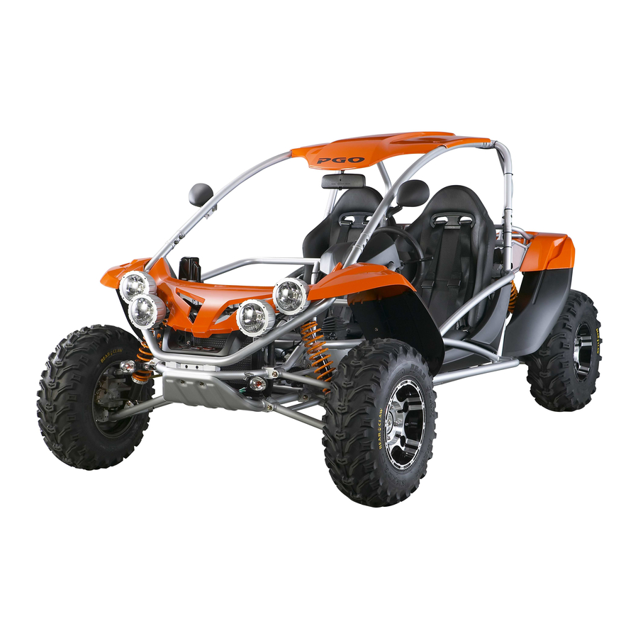
- Page 311 3. Basic Component locations Interior Mirror Seat Belt Back Mirror Steering Wheel Head Lamp Front Absorber Rear Signal Lamp Fuel Tank Rear absorber Rear/Brake Lamp Driving Shaft Muffler P.2-9 PGO BR-500 ENGINE...
- Page 312 When shifting the lever to “R”, you have to brake the vehicle (by the brake pedal)simultaneously, otherwise the engine will stop automatically for your safety. the above figure shows 3 controls levers, be aware they all shall be only operated when the vehicle is completely stationery! P.2-10 PGO BR-500 ENGINE...
- Page 313 Low speed range forward, heavy duty condition. UNLOCK: means the differential gear box is effective, usually used in High speed range forward, on-road condition. Shift the gear Only when the buggy is stationary for the machine’s good. P.2-11 PGO BR-500 ENGINE...
- Page 314 Attention! Although the vehicle allows you to start the engine at any gear positions, but keep in mind always shifting at “N” or “P” to start the engine is much safer for you! P.2-12 PGO BR-500 ENGINE...
- Page 315 Hand park adjusting nut Hand park cable adjusting nut Clearance adjusting nut for throttle Lock nut for throttle cable Stop bolt for “GO” pedal Adjusting nut for shifting cable Lock nut for differential control cable P.2-1 3 PGO BR-500 ENGINE...
- Page 316 PREFACE This manual offers all service specialists with the technological procedures of operation, maintenance, repairing for BugRacer (BR-500) show those whom may concern how to maintain in detail, repair, change parts, troubleshoot and reassemble, etc. At every important section we illustrate by assembly, explosion diagrams and photographs, if necessary, please check the diagrams already shown..
- Page 317 INDEX OF TOPICS CHARACTERISTICS OPERATION MAINTENANCE COOLING SYSTEM ELECTRIC SYSTEM VEHICLE ENGINE STEERING WHEEL AND SUSPENSIONS BRAKING SYSTEM INJECTION ENGINE PRIOR TO DELIVERY TIME CHART...
- Page 318 INDEX OF TOPICS CHARACTERISTICS...
- Page 319 12V-21W*2 BORE £p92 mm STROKE 69 mm COMPRESSION RATIO 10.5¡G 1 MAX. POWER/RPM 14.8kw/7250rpm AMX. TORQUE/RPM 24.0N-M/6000rpm IDLE RPM 1600¡Ó100 RPM IGNITION TRANSISTOR SPARK PLUG CR7EKB COOLING LIQUID STARTER ELECTRIC FUEL SUPPLY ELECTRIC PUMP LUBRICATION SEPARATED P.1-2 PGO BR-500 ENGINE...
- Page 320 When tighten screws or nuts, lock tightly as per specified locking torque, and in the sequence of cross direction. Use PGO, or PGO Recommended parts. After dismantling please wash all parts necessary for checking and grease all contact surface when reassembling.
- Page 321 Tightener fastening screws 11~13 Head fastening screws 10~12 FLYWHEEL COVER Flywheel fastening nut 115~125 Stator fastening screws 8~10 Blow-by recovery duct fastening screws Screws for fixing the free wheel on the 13~15 flywheel Stator wiring guide bracket screws P.1-4 PGO BR-500 ENGINE...
- Page 322 Anti- flapping roller fastening screw 17~19 Clutch ring nut 65~75 Internal air conveyor screws Water pump cover screws Outside transmission cover screws Flywheel cover screws 11~13 LUBRICATION Oil pump coupling screws 0.7~0.9 Oil pump fastening screws P.1-5 PGO BR-500 ENGINE...
- Page 323 Locking Torques Major Service Engine parts: Engine oil drain bolt Oil filter Hub gear oil drain bolt Engine coolant water drain bolt Bolts for cylinder head cover Reverse gear oil drain bolt P.1-6 PGO BR-500 ENGINE...
- Page 324 17 Park Brake fixture 2.0~3.0 18 Brake hose bolt 2.0~3.0 19 Braking sensor 2.5~3.0 20 Neutral sensor 3.5~4.0 21 Reverse gear socket nut 10.0~11.0 22 Muffler fixing bolts & nuts 3.5~4.0 23 Brake disk bolts 2.0~3.0 P.1-7 PGO BR-500 ENGINE...
- Page 325 Locking Torques Chassis parts: nut for tie-rod V.S. A-arm adjusting nut for tie rod Nuts for wheel rim Bolt for balance bracket Bolts for A-arm Bolts for cushion(lower & upper) P.1-8 PGO BR-500 ENGINE...
- Page 326 Nuts for rear swing arm V.S. brake hub Bolt for rear swing arm Nut for engine hanger V.S. engine Bolts for Reverse gear V.S. bracket Bolts for fixing muffler Bolts for engine V.S. engine upper bracket P.1-9 PGO BR-500 ENGINE...
- Page 327 Lithium soap and zinc oxide TUTELA ZETA 2 bearings, pin seats and grease NLG12 for the oscillating oscillating arm Reverse gear box oil Oil SAE 80W/90 of higher quality TUTELA ZC 90 than API GL3 specifications P.1-10 PGO BR-500 ENGINE...
- Page 328 **** NAME DIMENSION CLEARANCE CLEARANCE WHEN CLEARANCE NAME SEATED AFTER USE First compression lining 92 x 1,5 0,15 ~0,35 Second lining 92 x 1,25 0,25 ~0,50 0,65 Scraper ring lining 92 x 2,5 0,25 ~0,50 0,65 P.1-11 PGO BR-500 ENGINE...
- Page 329 0,4 +- 0,05 - 0,10 -+ 0,10 0,6 +- 0,05 + 0,10 -+ 0,185 0,8 +- 0,05 The values indicated with ??refer to recesses Driving shaft / crankcase axial clearance: 0.1 ~ 0.5 mm (when cold) P.1-12 PGO BR-500 ENGINE...
- Page 330 40,010 ~ 40,016 Cat. 2 40,016 ~ 40,022 Drivingshaft alignment Max admissible displacement: A = 0,15 mm B = 0,010 mm C = 0,010 mm D = 0,10 mm Specificequipment and tools: Driving shaft support.: 020074Y P.1-13 Comparator: 020335Y PGO BR-500 ENGINE...
Need help?
Do you have a question about the BR-500 and is the answer not in the manual?
Questions and answers