Table of Contents
Advertisement
Quick Links
DEAR CUSTOMERS¡G
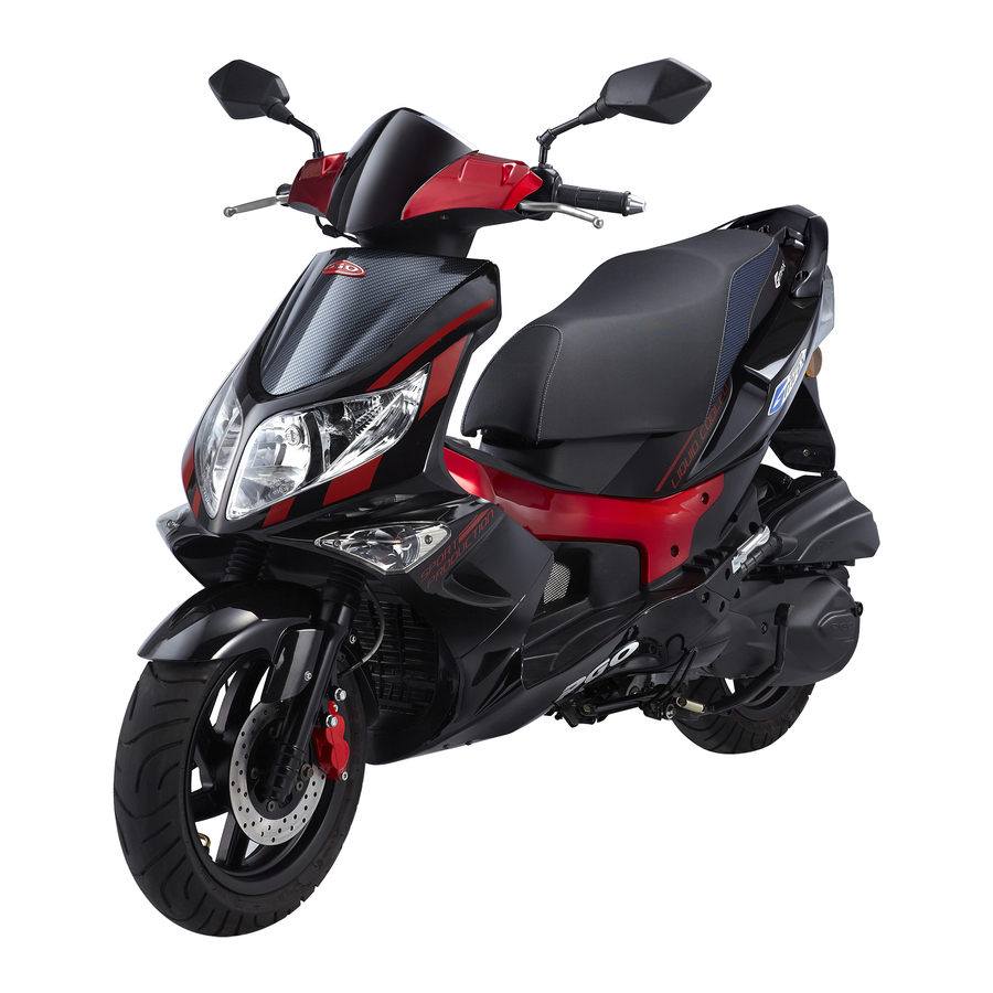
Thank you for buying G-MAX (ALLORO) of PGO
scooter. It is a fact that the efficiency and sustaining life of each
scooter depend heavily on the operating method of each user.
Thus this owner's manual will provide you a precise knowledge
of easy adjusting, sustaining and precaution for your scooter.
We hope you will read and check it carefully.
This manual includes 3 kinds of engine displacement:
l G-MAX 50 (ALLORO 50): abbreviated as "M2-50" is 2
stroke engine (2T), 50cc displacement.
l G-MAX 125 (ALLORO 125): abbreviated as "M2-125" is 4
stroke engine (4T), 125cc displacement.
l G-MAX 150 (ALLORO 150): abbreviated as "M2-150" is 4
stroke engine (4T), 150cc displacement.
Please recognize your scooter model clearly in order to read
the following instruments.
If there is any question, please do not hesitate to ask
your dealer for assistance.
Advertisement
Table of Contents

Related Manuals for PGO G-MAX 50


Summary of Contents for PGO G-MAX 50
- Page 1 We hope you will read and check it carefully. This manual includes 3 kinds of engine displacement: l G-MAX 50 (ALLORO 50): abbreviated as “M2-50” is 2 stroke engine (2T), 50cc displacement. l G-MAX 125 (ALLORO 125): abbreviated as “M2-125” is 4 stroke engine (4T), 125cc displacement.
-
Page 2: Table Of Contents
CONTENT Warranty Card.............1 Catalyst ............26 Scooter safety............2 Notation for operation and riding ...... 27 Part location............4 Starting the engine ......... 27 Identification............6 Warming up the engine........28 The function of switch & controller ....9 Brake operation..........29 Main switch............9 Engine initial run- in........ - Page 3 Check List before Delivery Name¡G Tel¡G Age¡G Sex¡G Address¡G Model¡G Engine No¡G VIN No¡G Delivery date¡G Year Month Dealer¡G N NO Check Item Check Item 1 Steering of Handle Bar 7 Tire Pressure 2 Gap of Brake Lever 8 Confirm Engine No & Document 3 Lights and Horn 9 Owner’s Manual 4 Fuel Tank and Fuel Kind...
-
Page 4: Warranty Card
PGO Warranty Card Name Telephone Registration date Address Displacement Engine NO . VIN. Model Customer Signature Dealer Signature... -
Page 5: Scooter Safety
SCOOTER SAFETY ¡¶WARNING .Scooter riding requires special afford on your part to ensure your safety. Know these requirements before you ride: SAFE RIDING RULES 1. Always make a pre-ride inspection(page 13) and perform any needed adjustments or repairs before you ride the scooter. - Page 6 5. Don't let other motorists surprise you. Use extra caution at intersections , parking lot entrances and exits, and driveways. 6. Keep both hands on the handlebars and both feet on the floorboards while riding. A passenger should hold on to the scooter or the feet on then passenger foot pegs. 7.
-
Page 7: Part Location
SEAT Part location: REAR RACK BACK MIRROR THROTTLE GRIP REAR LAMP FRT BRAKE LEVER AIR CLEANER REAR BRAKE LEVER KICK STARTER HEAD LAMP MAIN STAND FRT SIGNAL LAMP FUEL CAP SIDE STAND FRT BRAKE DISK... -
Page 8: Identification
IDENTIFICATION 1. Recognize your vehicle model according to license document or manufacturing document. Because this manual is suitable for all G-MAX (ALLORO) serial models, there are many different operations between every model. Once you see a model indication bar appears above the page, for example: The “... - Page 9 IDENTIFICATION 2.Engine No. is located (stamped) on the rear side of the left crankcase. 50 CC 125 / 150 CC NOTE: The upper row is model type, the lower row is the production serial numbers. Your dealer need this number for ordering the parts, please write down the engine no. for the ir reference.
- Page 10 IDENTIFICATION 3.Vehicle Identification Number (VIN) is located (stamped) inside the inner front cover. NOTE: The first 9 digitals are model type, the last 8 digitals are production serial numbers. Your dealer need this number for ordering the parts, please write down the engine no. for the ir reference.
-
Page 11: Main Switch
THE FUNCTION OF SWITCHES 1. MAIN SWITCH The main switch controls the ignition and lighting system, followings are the operation instruction. The power is on, engine can be started. The key can not be pulled out at this position. All the power is cut off. The key can be pulled out at this position. -
Page 12: 2.1 Speedometer
2.1 SPEEDOMETER 7 a b 1 SIGNAL INDICATOR (GREEN) When the blinker switch is shifted, this indicator will flash and tickling. 2 HIGH BEAM INDICATOR (BLUE) When the HI/LO beam switch is set on ‘HI’, this indicator will light on 3.ENGINE-OFF INDICATOR If this ind icator lights, the engine can not be started. - Page 13 2.2 SPEEDOMETER 6. ENGINE SPEED INDICATOR 7 b a Multiply the indicated digital by 1,000 rpm. (round per minute) 7. DIGITAL CLOCK this clock is powered by vehicle battery, there is not any individual battery inside it. Once replace the battery, you have to settle the present time again a.
- Page 14 2.3 SPEEDOMETER 1. SIGNAL INDICATOR (GREEN) When the blinker switch is shifted, this indicator will flash and tickling. 2. Engine oil replacement indicator When appear Red color, replace the 4T engine oil as soon as possible. 3. Insert the key to reset the engine oil replacement counter, it will become Green color again.
-
Page 15: Handlebar Controls
HANDLE-BAR CONTROLS 1. HI/LO BEAM SWITCH HI-The high beam is on LO-The low beam is on Press the lower part to make a passing signal. 2. Turn Signal Switch Move to ¡ö to signal a left turn, ¡÷ to signal a right turn. -
Page 16: Steering Lock
STEERING LOCK SEATLOCK To lock the steering, turn the handle all the way to Push the key and turn counterclockwise to open the left and turn the key from seat. then remove the key. NOTE: Do not turn the key to , while riding. -
Page 17: Fuel Tank Cap
FUEL TANK CAP KICK STARTER LEVER Insert the key into ignition switch, and keep Swing the lever outwardly. Kick the lever position. Push the key and turn down slowly till the gear stop, then kick the clockwise to open the fuel cap. lever down strongly to star the engine. -
Page 18: Luggage Compartment
LUGGAGE COMPARTMENT The luggage compartment is under the seat. NOTE: Whenever the seat is opened, there is a lamp 1.The max loading weight is 5 KGS. inside the luggage will light on. 2.If engine has been operating over a long time. The luggage compartment become hot. -
Page 19: Pre-Riding Inspection
PRE-RIDING INSPECTION Please do the inspection as following before riding: ITEM PROCEDURE PAGE FRONT BRAKE Check the brake function, clearance , brake oil level, see if it is leaking. 29,40 If necessary, may refill FMVSS DOT3(4) OR SAEJ 1703 brake oil. REAR BRAKE Check the brake function and clearance, proper adjustment if necessary. -
Page 20: Brake
BRAKE FRONT BRAKE Adjustment: The front brake will be on function when 1.Measure the distance of the rear brake lever hold the handle and pull the right hand lever. play before the brake starts to take hold. Free play should be:10¡ã20mm. 2.Make free play adjustments by turning the adjusting nut at the brake arm. -
Page 21: Brake Fluid
Go to the PGO dealer immediately when find the brake fluid is leaking. 3.DISK BRAKE PAD The leakage means the braking system has Please refer to page 36. Pl e ase go to the PGO deadly dangerous problem. Dealer when this brake needed repairing. ~19~... - Page 22 2T Engine ENGINE OIL for l Oil warning indicator This lamp will make self test (light ON) for about 2 seconds whenever turn on the main key, if it lights on again after self test, that reminds you have to fill the oil as soon as possible.
-
Page 23: Engine Oil
ENGINE OIL 1. 4T Engine (125 / 150 CC) l Engine oil shall be replaced per 1,000 kilometers. l Engine oil volume must be examined after engine warn- up 2¡ã3 minutes. Be sure to execute on flat road. l Draw out and examine the oil gauge. Please refill if the volume below the low warning line. -
Page 24: Air Cleaner
AIR-CLEANER 1. 4T Engine (100 / 125 CC) Wet paper filter element The air filter will keep dust away from the engine and also protect it against wearing out. Please ask the dealer to check & clean the filter periodically, or by yourself. (ref:page 33) ~22~... - Page 25 AIR-CLEANER The air filter will keep dust away from the engine and also protect it against wearing out. Please ask the dealer to check & clean the filter periodically, or by yourself. (ref:page 33) 2. 2T Engine (50 CC) Sponge filter element ~23~...
-
Page 26: Tire
TIRE 2.SIMPLE CHECK: To secure the best performance & extend Check the tire appearance before riding. life-span, please pay your attention to the Please ask your dealer for repairing or following: replacing if the appearance has been detected 1.TIRE PRESSURE significant worn out or stabbed by nails, or Be sure that tire pressure in accordance with glass. -
Page 27: Throttle Grip
THROTTLE GRIP l Turn the grip and check the clearance & operation situation. l Make sure the grip will automatically return to the original position. Ask your dealers for adjusting advice if necessary. LAMPS & SIGNAL LIGHTS Make sure the front lamp, rear lamp, brake lamp, turn signal lamp, tail lamp and all other indicator lights working well. -
Page 28: Catalyst
CATALYSTER (OPTIONAL DEVICE) Catalyst device is designed for decreasing air pollution from exhaust system and it is mounted inside the muffler. 1. Make sure to park your scooter away from flammable material, pedestrian or child to avoid danger due to yielding hot from muffler cover. 2. -
Page 29: Notation For Operation And Riding
NOTATION FOR OPERATION & RIDING 1. Please make sure you are familiar with all the operation system & function before riding. Please contact with your dealers if there’s any question. 2. Do not start the engine in a closed place due to potential gas, threat from poisonous exhaust amassed. 3. -
Page 30: Warming Up The Engine
WARMING UP THE ENGINE To protect the engine, please warm up the engine 1¡ã3 minutes before riding. Do not immediately accelerate when the engine is cold. NOTE: Please read the instruction “engine initial run- in” page26 before initial riding. Scooter riding (after warning up the engine): 1. -
Page 31: Brake Operation
BRAKE OPERATION 1. Release the throttle grip. 2. Press front and rear brake levers gradually. REAR FRONT NOTE: 1. Sudden stop will cause sliding or falling down. 2. Use the braking carefully while you are turning, improper use of brake may cause sliding. 3. -
Page 32: Engine Initial Run-In
ENGINE INITIAL RUN-IN 0~1,000 km riding will be the critical period regarding scooter life span. The new engine can’t afford too much loading during the first 1,000kms. Every part of the engine will be run- in to obtain the correct clearance in this period. Be sure to avoid prolonging the throttling out totally or any operation causing high temperature in the engine. - Page 33 PARKING: Turn off the engine and pull out the key when parking the scooter. NOTE: 1. Please park your scooter away from the child & pedestrians if the muffler is hot. Do not park your scooter on a slop or soft ground to avoid falling down. ~31~...
-
Page 34: Periodical Maintenance
2. This scooter is equipped with side stand safety switch, whenever you park it with side stand, then the engine can not be started for your safety. PERIODICAL MAINTENANCE To secure the most safe & effective performance, please check, adjust and lubricate your scooter periodically. Periodical maintenance and lubrication should be acknowledge as an important instruction. -
Page 35: Periodical Maintenance Table
Front fork* Leaking and function check ¡³ ¡³ ¡³ ¡³ ¡³ ¡³ ¡³ Steering head bearing* Check looseness. Adjust it if ¡³ ¡³ ¡³ required NOTE¡G 1.Items with “*” mark indicate our recommendation to have it done by PGO dealer. ~33~... - Page 36 ¡³ ¡³ ¡³ ¡³ ¡³ Adjustment* CO/HC Percentage. NOTE¡G 1. Items with “*” mark indicate our recommendation to have it done by PGO dealer. 2. “A” denotes that function check or replace it when the engine performance reduces significantly. ~34~...
- Page 37 NOTE 1¡G For 4T engine, the engine oil shall be changed completely after run- in period 300km or one month later. This can make sure the engine runs smoothly. NOTE 2¡G The exchange of brake fluid 1. After disassembling of brake main cylinder or caliper, do change the new fluid. 2.
-
Page 38: Exhaust Control System
Exhaust control system (only be valid for the bike equipped catalyst): Catalyster will not be possible to be withdrawn individual, the only you have to do is to maintain fuel, ignition, intake/exhaust system periodically. 1. Maintenance procedure of air clearer (see page 33). 2. -
Page 39: The Air Cleaner
THE AIR-CLEANER 4T Engine(125/150 cc) 2T Engine (50 cc) If there is too much accumulation of dust inside the air cleaner, it will reduce the output of engine performance and cause abnormal consumption of fuel. Procedures of changing the air element: 1. -
Page 40: The Spark Plug
THE SPARK PLUG Spark plug is one of the important parts of the engine and it is easy to be checked. According to spark plug condition, you may infer the situation of the engine. The ideal color of the electrode should be light brown. -
Page 41: Brake Adjustment
(a) Front brake: 10~20 mm (b) Rear brake: 10~20 mm Adjust the nut if necessary. NOTE: Please contact to PGO dealer if the clearance is incorrect. Rear brake check (only for Drum brake model) The indicator will help you to easily screen the status of brake function. -
Page 42: Brake Fluid Check
Front brake check Please acting the brake for checking. If the indicator almost reach M2-50 the disk, please ask your dealers to change it. NOTE: If the brake area is wet (getting water), the brake will be out of order and jeopardizing you. BRAKE FLUID CHECK M2-125/150 Insufficient brake fluid will make the air into the brake system and... -
Page 43: Front Fork Check
4.To avoid the water getting into the main cylinder, otherwise the boiling temperature of the brake oil will be declining make the air be obstructed. 5.Brake oil could reode the painting surface and plastic parts. If any oil were spilled out, please clean it immediately. -
Page 44: Fuse Replacement
FUSE REPLACEMENT 1. The fuse is located beside the battery. M2-50 2. Open the battery cover. 3. If the fuse is burned out, turn off the main switch and related switches, replace a correct fuse, then turn on and check the circuit function, please contact with your dealers if the problem remains. -
Page 45: Periodic Maintenance Record
Periodic Maintenance Record Plan Actual Dealer Plan Actual Dealer Date Date Sign. Sign. 14,000 1,000 15,000 2,000 16,000 3,000 17,000 4,000 18,000 5,000 19,000 6,000 20,000 7,000 21,000 8,000 22,000 9,000 23,000 10,000 24,000 11,000 25,000 12,000 26,000 13,000 27,000 Please decrease maintenance period when often driving in dusty areas. - Page 46 SPECIFICATIONS TYPE M2-50 M2-125 M2-150 DIMENSION overall length 1855mm 1855mm 1855mm overall width 730mm 730mm 730mm overall height 1170mm 1170mm 1170mm axles distance 1365 mm 1365 mm 1365 mm DRY WEIGHT 105KG 130KG 132KG ENGINE type 2 stroke 4stroke 4stroke model no.
-
Page 47: Specifications
SPECIFICATIONS TYPE M2-50 M2-125 M2-150 GEAR OIL model SAE 140 SAE 140 SAE 140 min. volume 90cc 90cc 90cc total volume 110cc 110cc 110cc AIR CLEANER SPONGE PAPER ELEMENT PAPER ELEMENT FUEL: gasoline UNLEADED ONLY UNLEADED ONLY UNLEADED ONLY capacity of tank 7.5L 7.5L 7.5L... - Page 48 SPECIFICATIONS TYPE M2-50 M2-125 M2-150 BULB VOL / WATT * Q’TY head lamp ( HI /LO) 12V 35W / 35W * 1 12V 35W / 35W * 1 12V 35W / 35W * 1 rear lamp / 12V 5W / 12V 5W / 12V 5W / stop lamp...
Need help?
Do you have a question about the G-MAX 50 and is the answer not in the manual?
Questions and answers