
Related Manuals for Grant Aerona HPAW65


Summary of Contents for Grant Aerona HPAW65
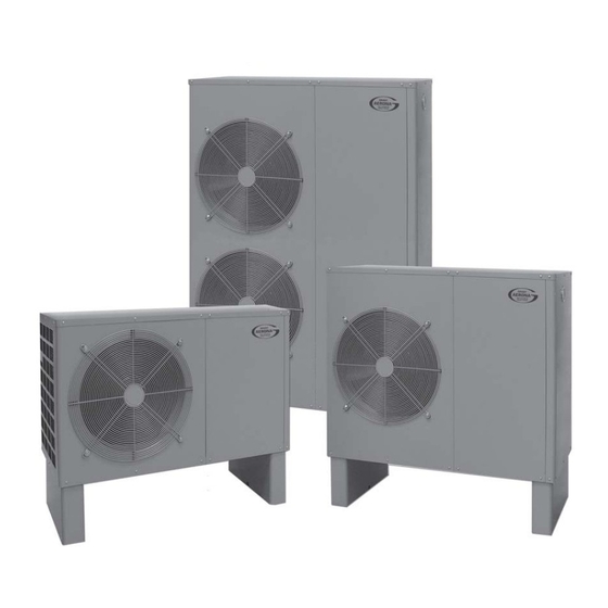
- Page 1 Grant Aerona Air Source Heat Pump Air to Water Heat Pump Range Installation & User Instructions Tested to BS EN 14511 Part No. DOC.87 Rev.05 January 2011...
- Page 2 STOP! Before continuing with the installation of your new Aerona Heat pump, please spend a few minutes confirming the suitability of the Heat Pump to your system. Failure to do so may result in poor performance and wasted time. Has a heat loss calculation been carried out? Is this system designed for Mono or Bivalent If Mono, total heating capacity? If Bivalent, what is the load capacity of Heat Pump?
- Page 3 Failure to follow this legislation will invalidate all warranties. Please seek advice from a competent person before commencing any electrical work. CE Marking The Grant Aerona range of Air Source Heat Pumps are CE marked and conform to the requirements of the following Directives and Standards: Low Voltage 73/23 EEC, modified 93/68 EEC.
-
Page 4: Table Of Contents
Contents Stop! Domestic Hot Water 9.1 Temperature Control Legislation 9.2 Heat Pump Cylinders Contents 9.3 Temperature Boost Introduction 10 Filling the System 1.1 General Information 10.1 Filling and Venting - Sealed Systems 1.2 Warranty 10.2 Flushing and Corrosion Protection 1.3 Important Advice 10.3 Antifreeze 1.4 Immersion Heater 11 Commissioning... -
Page 5: Introduction
Description of fault together with any 3. The heat pump contains high relevant fault codes pressures and high temperatures The Grant Aerona Heat Pump is a low during normal working conditions. water content – low temperature heat Please ensure that the caller is... -
Page 6: Specifications And Controls
2 Specifications and Controls 2.1 Specifications Model HPAW65 HPAW85 HPAW110 HPAW130 HPAW155 Heating Capacity 6.78 8.73 11.32 12.58 15.5 Max. Running Current at 240V* Power supply 220/240 220/240 220/240 220/240 220/240 Phase Single Single Single Single Single Frequency Mechanical Protection IP X4 IP X4 IP X4... -
Page 7: Main Components
2.2 Dimensions 1120 Flow Electrical inlet glands Return Front View Rear View Figure 2-3: HPAW155 model 2.3 Main Components Evaporator coil Control panel Position of Immersion (cover removed) heater with Auto air vent Mains supply terminals Heating controls terminals ATC controller connection plug Compressor... -
Page 8: Heat Pump Curves
Figure 2-6: Grant HPAW85 Figure 2-9: Grant HPAW155 NOTE Water Flow Temperature 35˚C All Grant Aerona heat pumps have been independently third party 50˚C tested to BS EN 14511. The COP data given above is based on 7˚C ambient air and 35˚C water temperature. -
Page 9: Pump Curves
2.5 Pump Curves Wilo-Classic Star Flow (m Figure 2-10: Pump curve for HPAW65, HPAW85, HPAW110 & HPAW130 15.5kW Pump Curve PUN-200E Flow (m Figure 2-11: Pump curve for HPAW155 2.6 Heat Pump Operating Sequences Pump Pump Compressor Compressor 4-way Valve 4-way Valve Heat Defrost... -
Page 10: Controls
The BTC allows for 2 different design temperatures to be entered, maximising the efficiency of the Grant Aerona heat pump. The details of these settings can be found in Section 11 of this manual. All other controls (programmers,... -
Page 11: Siting The Heat Pump
3 Siting the Heat Pump 3.1 Position 1. Base The heat pump should be installed on a flat trowelled finished concrete base 150mm thick. This base should extend at least 100mm beyond the unit on three sides. The edge of the concrete base on the 300mm side closest to the building should minimum... -
Page 12: Orientation
To ensure maximum efficiency Cooler ambient air from the Grant Aerona heat pump, position the unit on a warmer side. In order of preference, site the unit on a South face followed by either South East or South West, then by East or West. -
Page 13: Hydraulic Diagrams
Programmer drawings. They are not intended to describe complete systems, nor any particular system. Cylinder It is the responsibility of the Stat system designer, not Grant Room Stat Engineering UK Ltd., to determine the necessary components for and Heating Load... -
Page 14: S-Plan Type - Bivalent
They are not intended to describe complete systems, nor any particular system. It is the responsibility of the system designer, not Grant Engineering UK Ltd., to determine the necessary components for and configuration of the particular system being designed including any additional... -
Page 15: Extended S-Plan Type - Bivalent
Heating Load for 2 mins. Refer Maximum return temp. Outside to Section 11.4 wall 48˚C Room Stat Boiler Circulating Flow Pump (see note below) Grant Aerona Heat Pump Isolating valve Return Primary Auto Bypass Valve Flexible Pump pipe Isolating valve... -
Page 16: Buffer Tanks
It is the responsibility of the should be used. system designer, not Grant Engineering UK Ltd., to NOTE 1. It may act as an initial boost when a determine the necessary... -
Page 17: Extended S-Plan With Buffer - Monovalent
Internal wiring centre Programmer Cylinder Stat Room Stat Flow Heating Load Heat Pump Room Outside Stat wall Flow Grant Aerona Buffer Heat Pump tank Isolating valve Cylinder Stat Flexible Primary pipe Pump Isolating valve Return Figure 4-6: Monovalent system - with Buffer and extended S-Plan type controls... -
Page 18: System Design Criteria
-3˚C and that the house comfort temperature will be 21˚C. Refer to Section 6 to determine the size Example: A Grant Aerona HPAW65 The BTC incorporated in the heat of radiators required for your Heat Pump with a rated output of pump will adjust the output installation. -
Page 19: Calculating Radiator Sizes
6 Calculating Radiator Sizes Existing Systems Most existing wet heating systems will With the advent of condensing boilers, However, as heat pumps work at use radiators as emitters. When the most installations were found to have temperatures lower than even this, it is original system was installed, the oversized radiators and as such, little or important that each radiator is checked... -
Page 20: Sealed Systems
The following components are required These items may already be installed on The filling loop can be sited anywhere in to use the Grant Aerona heat pump as the existing system. If so, they should the system, but it must always be sited part of a sealed heating system. -
Page 21: Electrical
8.1 General The Grant Aerona Heat Pump is very simple to install and to wire. The units are designed NOTE to meet the need for simplicity – both in installation and in servicing. As a result, the wiring involved is both minimal and simple compared to other heat pumps available. -
Page 22: Controller
8 Electrical Heat pump S-Plan controls connections C CH HW Earth connections have been excluded for clarity. Ensure all earth connections are made Limit Control prior to energising. Room Programmer Thermostat Figure 8-2: S-Plan type system for connection to Aerona heat pump 8.3 Controller NOTE Note that both wires from Gr (grey) -
Page 23: Mains Supply Cable
8.4 Mains Supply Cable Always assume maximum possible load when considering cable sizing. All Grant Aerona Heat Pumps contain a 3kW immersion element as a boost The cable supplying power from the heat source. This element will energise consumer unit to the heat pump must... -
Page 24: Heat Pump Wiring Diagrams
8 Electrical 8.5 Heat Pump Wiring Diagrams Heat pump with 3kW electric element 230 Vac 24 Vac Fuse Compressor Heater Compressor Orange motor 4-way valve Relay Expansion Valve Pump Ret Gas Sensor Ext Temp Sensor Coil Temp Sensor Dis Gas Sensor Ret Temp Sensor Disconnect Electric Element... - Page 25 Heat pump with 6kW electric element 230 Vac 24 Vac The 6kW immersion Fuse Compressor element is ONLY Heater available as a factory fitted option Compressor Orange motor 4-way valve Relay Expansion Valve Pump Ret Gas Sensor Ext Temp Sensor Coil Temp Sensor Dis Gas Sensor Ret Temp Sensor...
-
Page 26: System Control Wiring Diagrams
8 Electrical 8.6 System Control Wiring Diagrams Heat pump S-Plan controls connections Fused Isolator CH HW 9 10 Limit Control Room Programmer Thermostat Earth connections have been excluded for clarity. Ensure all earth connections are made 230V 50Hz prior to energising. Figure 8-10: Domestic hot water connection diagram Heat pump S-Plan controls... -
Page 27: Wiring Diagrams
8.7 Wiring Diagrams Return sensor Supply sensor 230V/24 Vac Transformer Outdoor sensor Heat pump S-Plan controls C CH HW connections Heating Zone Valve Zone Valve Fused Isolator 6 7 8 9 10 Limit Control Cylinder Thermostat Room Programmer Thermostat 3 kW Immersion element Circulating Pump... - Page 28 8 Electrical 8.7 Wiring Diagrams Return sensor Supply sensor 230V/24 Vac Transformer Outdoor sensor Heat pump S-Plan controls C CH HW connections Heating Zone Valve Zone Valve Fused Isolator 6 7 8 9 10 Limit Control Cylinder Thermostat Room Programmer Thermostat Fused double Circulating Pump...
-
Page 29: Bivalent Systems
Heat pump S-Plan controls connections CH HW Cylinder Thermostat Room Programmer Thermostat Heat pump 1 2 3 S-Plan controls 230V C CH HW connections Cylinder 50Hz Thermostat Figure 8-14: Connection diagram for Grant solar thermal system Figure 8-15: Buffer tank thermostat... -
Page 30: Domestic Hot Water
HPAW130 13.0 transfer the heat efficiently. HPAW85 HPAW155 15.5 HPAW110 11.0 Grant has a range of seven single coil HPAW130 13.0 (from 120 to 400 litres) and five twin coil 9.3 Temperature Boost HPAW155 15.5 (from 170 to 400 litres) unvented... - Page 31 HW Where a 3-phase supply is present, kit from Grant Engineering UK Ltd. For channel of the programmer is in an ON ensure that BOTH the Immersion details of this Automatic Domestic Hot condition.
-
Page 32: Filling The System
7. Check the operation of the safety valve (as supplied in the Sealed 1. To vent the heat pump – All Grant Both the thermal fluid and biocide System kit) by turning the head... -
Page 33: Commissioning
Switch off power to the heat pump immediately, and purge any remaining air from the system. IMPORTANT Grant Aerona heat pumps should be stored and transported in an upright position. If not, the heat pump MUST be positioned in an upright position for... -
Page 34: Setting The Atc Controller
11 Commissioning 11.2 Setting the ATC Controller Note – It is possible to switch from NOTE when the ATC is The main purpose of the ATC controller switched OFF by pressing the M is to give an overall maximum button. temperature control over the heat If no button is pressed for a period pump. -
Page 35: Additional Operating Information About The Atc
Take a note of these settings and write them in the table on page 34. backup heater (and trace heater) will be energised to increase the heat output of IMPORTANT - Only set parameters as shown above unless the heat pump. instructed otherwise by Grant UK. - Page 36 11 Commissioning To check for Heat Pump operation: NOTE When is shown on the display, this indicates Heat pump is operating. This increase in efficiency, due to When ‘Dem’, are not weather compensation in the CH showing on the display indicates no mode, has NOT been taken into demand from either Heating or DHW, account in determining the COP’s...
-
Page 37: Setting The Btc Controller
DIFF parameter may not be displayed Take a note of these settings and write them in the table on page 34. IMPORTANT - Only set parameters as shown above unless instructed otherwise by Grant UK... -
Page 38: Record Of Atc And Btc Settings
11 Commissioning 11.5 Record of ATC and BTC Settings Please complete the following settings: Parameter Description Set Value Return water temperature to start electrical heater ˚C Max return water temperature setting ˚C Defrost cycle mins Coil temperature point to start defrosting ˚C Coil temperature point to stop defrosting ˚C... -
Page 39: Servicing & Maintenance
12 Servicing & Maintenance 12.1 General 12.3 Condensate Disposal WARNING Grant Aerona Heat Pumps require only Check that condensate drain holes in the minimum of routine servicing and the bottom of the unit are not blocked. maintenance. This basically consists of If it is necessary to carry out any 12.4 Heating System... -
Page 40: Fault Finding
– and not either room or cylinder thermostats the Grant technical helpline, as we to the CH and DHW motorised will only direct you to contact an DO NOT attempt to test the (zone) valves. - Page 41 13.7 General Notes 230 Vac 24 Vac Fuse For diagram of 6kW Compressor immersion heater Heater refer to Figure 8-9. Compressor Orange motor 4-way valve Relay Expansion Valve Pump Ret Gas Sensor Ext Temp Sensor Coil Temp Sensor Dis Gas Sensor Ret Temp Sensor Disconnect Electric Element...
- Page 42 13 Fault Finding Temperature Resistance Temperature Resistance Temperature Resistance Temperature Resistance ˚C ˚C ˚C ˚C 37.4111 13.0055 5.1978 2.3276 35.5384 12.4391 5.0000 2.2493 33.7705 11.9008 4.8109 2.1740 31.1009 11.3890 4.6300 2.1017 30.5237 10.9023 4.4569 2.0320 29.0333 10.4393 4.2912 1.9651 27.6246 9.9987 4.1327 1.9007...
-
Page 43: 14 Spare Parts
14 Spare Parts List 12 Vac Transformer Relay Power capacitor 24 Vac Transformer Relay Figure 14-1: Heat pump control panel components Part Number Description HPAW65 HPAW85 HPAW110 HPAW130 HPAW155 HPAS10 Power Capacitor 50µF HPAS11 Power Capacitor 60µF HPAS12 Power Capacitor 70µF HPAS13 Power Capacitor 100µF HPAS14... -
Page 44: Accessories
Kit 3 (Grant Ref. HPAW55K50) 15.2 Immersion Heater Kits 50 litre expansion vessel kit These are required when the Grant Kit 4 (Grant Ref. HPDHWBK1) For use on heating systems with a Aerona Heat Pump is used as part of... -
Page 45: Glossary Of Terms
16 Glossary of Terms Efficiency Heat Exchanger The word “efficiency” is defined as the A component that allows the ratio of useful heat output to energy transference of heat from one circuit to input. For example, if we use 1 kW of another without the two circuits mixing. -
Page 46: Warranty
4. The Grant Heat Pump must be months from the date of purchase Free of Charge Repairs: installed by a competent installer provided the heat pump is installed in... -
Page 47: Extended Warranty
17.2 Extended Warranty For further peace of mind Grant Engineering (UK) Ltd offer the option to insure all the components of your Grant Air Source Heat Pump for a further three years, following on from the two year product warranty period. For a... - Page 48 GRANT ENGINEERING (UK) LTD Hopton House, Hopton Industrial Estate, Devizes, Wiltshire. SN10 2EU Telephone: 01380 736920 Fax: 01380 736991 Email: info@grantuk.com Website: www.grantuk.com...
Need help?
Do you have a question about the Aerona HPAW65 and is the answer not in the manual?
Questions and answers