
Related Manuals for Grant Aerona 290


Summary of Contents for Grant Aerona 290
- Page 1 Grant Aerona 290 Air to Water Air Source Heat Pump Range Installation & Operating Instructions UK | DOC 0204 | Rev 1.0 | October 2024...
- Page 2 This manual is accurate at the date of printing but will be superseded and should be disregarded if specifications and/or appearances are changed in the interests of continued product improvement. However, no responsibility of any kind for any injury, death, loss, damage or delay however caused resulting from the use of this manual can be accepted by Grant Engineering (UK) Limited, the author or others involved in its publication.
-
Page 3: Table Of Contents
Conformity - HPR2904 & HPR29065 3.14 Completion 13.2 UKCA - Safety Declaration of 3.15 Installation Checklist Conformity - HPR2909, HPR29012 & 3.16 Aerona 290 Packaging HPR290155 SEALED SYSTEMS 14 HEALTH & SAFETY INFORMATION Introduction 14.1 General Filling the Sealed System 14.2... -
Page 4: Introduction
This will not provide antifreeze protection to the entire The Grant Aerona 290 heat pump is to be used only with the system. Grant Aerona Smart heat pump system controller which is... -
Page 5: Dno Application
Full details on application/notification process can be found by scanning the following QR code. Refer to Table 1-1 for details. PRODUCT CONTENTS The Aerona 290 comes supplied on a single pallet. The items that Table 1-1: Connect direct QR code are included are indicated in Table 1-3. -
Page 6: Remote Controller Kits
1.8.1 GRANT AERONA SMART CONTROLLER mixing valve with non pre-plumbed cylinder. The Grant Aerona 290 is designed to work exclusively with the Grant Aerona Smart heat pump system controller. Table 1-7: Installation Pack Q If you are using a Grant QR Smart Pre-plumbed cylinder with the... -
Page 7: Heat Pump Components
1.10 HEAT PUMP COMPONENTS 1.10.1 HPR2904 Refrigerant leakage sensor DC fan Automatic air vent Four way valve Water flow switch Water pressure sensor Water side heat exchanger DC inverter compressor Electric expansion valve Air side heat exchanger Chassis heater Electric control box Variable frequency pump Figure 1-1: Main components - HPR2904 1.10.2... - Page 8 Refrigerant leakage sensor 1.10.3 HPR29012 Automatic air vent DC fan Refrigerant leakage sensor Automatic air vent Water flow switch Four way valve Water flow switch Four way valve Water side heat exchanger Water pressure sensor Water side heat exchanger Safety valve DC inverter compressor Water pressure sensor Safety valve...
- Page 9 DC fan Refrigerant leakage sensor 1.10.4 HPR290155 DC fan Refrigerant leakage sensor Automatic air vent Automatic air vent Four way valve Water flow switch Four way valve Water flow switch Water side heat exchanger Water side heat exchanger Water pressure sensor Safety valve Water pressure sensor DC inverter compressor...
-
Page 10: Hydraulic Module
1.11 HYDRAULIC MODULE Components of the hydraulic module of each unit model: 1.11.1 HPR2904 1.11.3 HPR2909 Figure 1-5: Hydraulic module - 4kW Figure 1-7: Hydraulic module - 9kW 1.11.2 HPR29065 1.11.4 HPR29012 & HPR290155 Figure 1-6: Hydraulic module - 6.5kW Figure 1-8: Hydraulic module - 12kW &... - Page 11 Table 1-10: Key items for Figures 1-5 to 1-8 Code Assembly unit Explanation Automatic air purge valve Remaining air in the water circuit will be automatically removed from the water circuit Refrigerant gas pipe Conducts refrigerant in gas state Three temperature sensors determine the water and refrigerant temperature at various Temperature sensor points in the water circuit Refrigerant liquid pipe...
-
Page 12: Technical Data
2 TECHNICAL DATA HEAT PUMP TECHNICAL DATA Table 2-1: Technical Data Model Unit HPR2904 HPR29065 HPR2909 HPR29012 HPR290155 Heating capacity (BS EN 14511 - air: -5°C / water: 55°C) 4.10 6.76 9.21 12.00 15.57 COP (BS EN 14511 - air. -5°C / water 55°C) 2.48 2.27 2.31... -
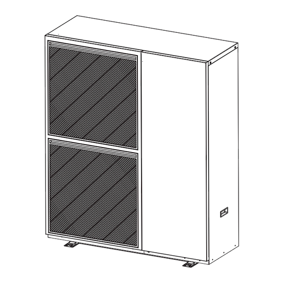
Page 13: Heat Pump Dimensions
HEAT PUMP DIMENSIONS 1155 Figure 2-1: HPR2904 heat pump dimensions 1223 Figure 2-2: HPR29065 & HPR2909 heat pump dimensions Section 2: Technical Data Page 13... - Page 14 1155 Figure 2-3: HPR29012 & HPR290155 heat pump dimensions Page 14 Section 2: Technical Data...
-
Page 15: Installation Information
Aerona 290 4 kW shipping company. Aerona 290 6.5 & 9 kW Aerona 290 12 & 15.5 kW ! NOTE ! Check that the model, specifications and quantity of units delivered as ordered. -
Page 16: Introduction
A typical condensing oil or gas fired boiler operates with a flow For the heat pump to operate satisfactorily, install it as outlined in of 70°C and a return of 50°C, i.e. with a DT of 20°C. The Grant this installation manual. -
Page 17: Regulations
REGULATIONS Installation of a Grant Aerona 290 heat pump must be in accordance with the following recommendations: Strong wind Strong wind • National Building Regulations, e.g. Approved Documents L & G. • Local Bylaws (Check with the Local Authority for the area). -
Page 18: Preparation For Installation
3.5.1 R290 REFRIGERANT The Grant Aerona 290 heat pump contains R290 refrigerant gas. The density of this gas is greater than that of air, so in the event of leakage it tends to disperse and stratify, accumulating in niches, depressions in the ground or underground regions. - Page 19 3.6.3 GROUND INSTALLATION IN A BUILDING CORNER 3.6.4 WALL INSTALLATION IN A LOW POSITION Figure 3-8: Ground installation in a corner Figure 3-9: Wall installation in a low position Table 3-5: Ground installation in a corner protective zone Table 3-6: Wall installation in a low position protective zone Item Distance (mm) Dimension...
- Page 20 3.6.5 WALL INSTALLATION IN A RAISED POSITION 3.6.7 RAISED WALL INSTALLATION IN A RIGHT-HAND CORNER Figure 3-10: Raised wall installation Figure 3-12: Raised Wall installation in a right-hand corner Table 3-7: Raised wall installation protective zone Table 3-9: Raised wall installation in a right corner protective zone Dimension Distance (mm) Dimension...
- Page 21 3.6.9 CLEARANCES The following minimum clearances must be used to enable the product to be easily commissioned, serviced and maintained and allow adequate air flow in and out of the heat pump. For ground installation clearances, refer to Table 3-10 and Figure 3-13.
-
Page 22: Wall Mounted Installations
WALL MOUNTED INSTALLATIONS 3.7.2 CONNECTING THE HEATING SYSTEM TO THE All five sizes of Grant Aerona 290 heat pump can be wall mounted HEAT PUMP at a safe height, with the top of the unit no more than 2m above... -
Page 23: System Connections
Grant UK offer an insulated 50 litre Internal volumiser fitted with a 3kW immersion heater to be installed on the return to the heat pump. This is designed to provide both the necessary volume and, when required, assistance for defrost functions in cold ambient temperatures. -
Page 24: Hydraulic Diagrams
Grant UK expect the user to take adequate manufacturer’s instructions. precautions to protect their home and contents in the event of a power cut;... -
Page 25: Completion
For wall mounted installations, help lessen the environmental impact of our products. improper installation work may result in accidents due to The packaging for your Aerona 290 air source heat pump should equipment falling. be handled as follows:... -
Page 26: Sealed Systems
All fittings used in the system must be able to withstand pressures up to 3 bar. Radiator valves must comply with the requirements of All Grant Aerona 290 heat pumps must be used with sealed BS 2767:1991. systems complying with the requirements of BS EN 12828, BS EN 12831 and BS EN 14336. -
Page 27: Pressure Relief (Safety) Valve Operation
This valve is opened from factory, when doing the installation in jobsite, this valve will automatically discharge the air in the water system during the pump operation. Figure 4-1: Automatic Air Vent Figure 4-2: Water circuit connection ! NOTE ! ! NOTE ! The air charge pressure may be checked using a tyre Never use Zinc-plated parts in the water circuit. -
Page 28: Domestic Hot Water
DHW cylinder Reheat V x ρ x c x ΔT Time with the use of a Grant Immersion relay. If required, the user can Time set temperature and time limits on when the immersion relay will Reheat 210 x 1 x 4.182 x 20... -
Page 29: Legionella
For protection against Legionella the temperature can be periodically to 60°C using the supplied Grant Aerona Smart Controller. It is possible to use the Aerona 290 heat pump to raise the DHW cylinder to around 50 to 55°C during the standard operating modes. -
Page 30: Electrical
Figure 6-1: Heat pump, isolator and consumer unit ! NOTE ! A Type F Residual current device (RCD) can be used with all Aerona 290 heat pumps with DC residual current measuring under 10mA across all models. Table 6-1: Electrical supply details... - Page 31 6.1.1 CONNECTING MAINS SUPPLY Guide the cable into the hydraulic PCB housing through the holes in the bottom. Remove the side panel of the R290 heat pump (left side panel when viewing from the rear) and the Open the cable clamp and pass the power cable Hydraulic PCB module panel.
- Page 32 Strip the ends of connecting cables in accordance with Figure 6-6. Crimp terminals with insulating sleeves can be used if required as illustrated in Figure 6-6 for connecting the wires to the terminal block. Stranded conductors shall not be soldered. •...
-
Page 33: Tightening Torques
Smart Controller, Refer to Section 7. INTERNAL ELECTRIC HEATERS The Grant Aerona 290 comes factory fitted with a number of electric heaters that aid various internal functions within the heat pump. Refer to table 6-4 for heaters and related electrical specifications. - Page 34 Page intentionally left blank. Page 34...
-
Page 35: Smart Controller
G2 socket. For more information refer to For information relating to the installation requirements of the Section 5 of your supplied manual: Grant Aerona Smart controller, refer to Section 3 of your supplied • DOC 0203 - for systems without Grant QR pre-plumbed... -
Page 36: Operation
8 OPERATION STOP OPERATION 8.3.3 STARTUP CONTROL FOR SPACE HEATING AND DHW OPERATION The stop operation occurs for one of the following reasons: Refer to Table 8-1 for the Component control during startup in Normal shutdown: The heat pump will stop running when the space heating and DHW modes. -
Page 37: Protection Control
WATER CIRCUIT ANTI-FREEZE system displays P02 protection and the unit stops running. When The Grant Aerona 290 software includes special functions that the discharge pressure drops below 2.8Mpa, the compressor use the heat pump to protect the entire system against freezing. -
Page 38: Special Control
If the water flow temperature in the system drops below 4°C and 8.6.2.1 DEFROST ENTER CONDITIONS the ambient air temperature is below 4° (Refer to section 3.12.2), In order to recover heating capacity, the defrosting operation the unit will activate the plate heat exchanger heater. is conducted when the air side heat exchanger of the unit is performing as a condenser. - Page 39 Plate heat exchanger Water out Flow temperature Balance tank Low pressure sensor 4-way valve T4 Ambient temp. sensor Water in Discharge temp. sensor Return temperature Suction temp. sensor Filter DC fan high pressure sensor T5 Heating liquid temp. sensor Electronic expansion valve High pressure switch Air side heat exchanger Filter...
-
Page 40: Commissioning
9.1.3 TURNING THE SMART CONTROLLER ON manual: The power switch for the Grant Aerona Smart controller is located on the left side of the wiring centre, when facing it from the front. • DOC 0203 - for systems without Grant QR pre-plumbed... -
Page 41: User Settings
BALANCING THE PRIMARY CIRCUIT 9.3.1 USER SETTINGS For information relating to the User settings menu on of the Grant With the heat pump installed as described in these installation Aerona Smart controller, refer to Section 7.9 of your supplied instructions, any hot water cylinders connected to the system... -
Page 42: Servicing
Checks to electrical devices Repair and maintenance to electrical components shall Prior to performing any annual service or repair work on a Grant include initial safety checks and component inspection Aerona 290 heat pump the following guidance must be followed: procedures. -
Page 43: Servicing & Maintenance Procedure
Leak detection fluids are suitable for use with most refrigerants but the use of detergents containing chlorine Grant Aerona 290 heat pumps require only the minimum of shall be avoided as the chlorine may react with the routine maintenance. This should be carried out on an annual refrigerant and corrode the copper pipework. -
Page 44: Condensate Disposal
Operation of pressure relief valve For information relating to the Heat pump accessibility on the • Heating system pressure – top up if necessary Grant Aerona Smart controller, refer to Section 9 of your supplied manual: • Correct concentration of corrosion inhibitor/biocide protection •... -
Page 45: Hydraulic Pcb Dip Switches
Table 10-3: Dip switch Block 3 (SW3) Switch Description OFF / OFF Enable 3kW Internal Electric pipe heater. (not available on UK Aerona 290 models) 1 & 2* ON / ON Disable 3kW Internal Electric pipe heater (not available on UK Aerona 290 models) 3 &... -
Page 46: Fault Finding
11 FAULT FINDING 11.1 ERROR CODE DISPLAY ! NOTE ! When there is a fault with the heat pump, an error code will be displayed on the touch screen display. A list of all error codes and corrective actions can be found in Error codes displayed may be due to incorrect dip switch Table 11-1. - Page 47 Fault number Fault name Failure analysis Diagnosis method Solution Refrigerant Leak in refrigerant circuit Check whether there is Repair leak in refrigerant circuit leakage fault leakage in refrigerant circuit Refrigerant leakage sensor Replace refrigerant leakage failure Check whether refrigerant sensor leakage sensor is normal Hydraulic PCB is faulty Replace Hydraulic PCB...
- Page 48 Fault number Fault name Failure analysis Diagnosis method Solution DC bus voltage is too low DC bus voltage is too high AC current protection (input current) IPM module is abnormal PFC abnormal Compressor failed to start Compressor phase loss E22* Inverter Module reset Compressor...
- Page 49 Fault number Fault name Failure analysis Diagnosis method Solution AC input voltage is abnormal E35* Drive EEPROM error Power off reset Check all connections from the Refrigerant PCB (or Ensure all connections are Cables incorrectly connected Refrigerant & Drive PCB for E37* Reserved made correctly.
-
Page 50: Spare Parts
12 SPARE PARTS 12.1 HPR2904 - 4KW Product Product Item Description Item Description code code Front panel HPR481 Evaporator coil temperature sensor (T3) - 4kW, HPR600 6.5kW & 9kW Grill HPR380 Refrigerant suction temperature sensor (TH/TA) HPR360 HPR602 - 4kW, 6.5kW & 9kW Fan Motor HPR460 Liquid Tube temperature sensor (T5/TB)- 4kW,... - Page 51 12.1.1 EXPLODED DIAGRAM - HPR2904 - 4KW Section 12: Spare Parts Page 51...
-
Page 52: Hpr29065 - 6.5Kw
12.2 HPR29065 - 6.5KW Product Product Item Description Item Description code code Front panel - 6.5kW & 9kW HPR483 Refrigerant suction temperature sensor (TH/TA) HPR602 - 4kW, 6.5kW & 9kW Grill - 6.5kW & 9kW HPR381 Liquid Tube temperature sensor (T5/TB) - 4kW, HPR603 Fan - 6.5kW &... - Page 53 12.2.1 EXPLODED DIAGRAM - HPR29065 - 6.5KW Section 12: Spare Parts Page 53...
-
Page 54: Hpr2909 - 9Kw
12.3 HPR2909 - 9KW Product Product Item Description Item Description code code Front panel - 6.5kW & 9kW HPR483 Refrigerant suction temperature sensor (TH/TA) HPR602 - 4kW, 6.5kW & 9kW Grill - 6.5kW & 9kW HPR381 Liquid Tube temperature sensor (T5/TB) - 4kW, HPR603 Fan - 6.5kW &... - Page 55 12.3.1 EXPLODED DIAGRAM - HPR2909 - 9KW Section 12: Spare Parts Page 55...
-
Page 56: Hpr29012 - 12Kw
12.4 HPR29012 - 12KW Product Product Item Description Item Description code code Front panel - 12kW & 15.5kW HPR488 Liquid Tube temperature sensor (T5) - 12kW & HPR611 15.5kW Grill - 12kW & 15.5kW HPR382 Return temperature sensor (TA) - 12kW & HPR609 Fan - 12kW &... - Page 57 12.4.1 EXPLODED DIAGRAM - HPR29012 - 12KW Section 12: Spare Parts Page 57...
-
Page 58: Hpr290155 - 15.5Kw
12.5 HPR290155 - 15.5KW Product Product Item Description Item Description code code Front panel - 12kW & 15.5kW HPR488 Evaporator coil temperature sensor (T3) - 12kW HPR607 & 15.5kW Grill - 12kW & 15.5kW HPR382 Refrigerant suction temperature sensor (TH) - HPR616 Fan - 12kW &... - Page 59 12.5.1 EXPLODED DIAGRAM - HPR290155 - 15.5KW Section 12: Spare Parts Page 59...
-
Page 60: Declaration Of Conformity
Regulations as below The Technical Construction Files are retained at the Manufacturer's location. Product: Air to Water Heat Pump Model: GRANT AERONA HPR2904 GRANT AERONA HPR29065 2012 Grant Engineering (UK) Ltd Frankland Road | Blagrove | Swindon |SN5 8YG +44(0)1380 736920 | info@grantuk.com |www.grantuk.com... - Page 61 Date of issue Authorised Signatory Neil Sawers Technical Manager Grant Engineering (UK) Ltd Frankland Road | Blagrove | Swindon |SN5 8YG +44(0)1380 736920 | info@grantuk.com |www.grantuk.com REGISTERED IN ENGLAND No: 3196757. REGISTERED OFFICE: AS ABOVE Section 13: Declaration of Conformity...
- Page 62 Regulations as below The Technical Construction Files are retained at the Manufacturer's location. Product: Air to Water Heat Pump Model: GRANT AERONA HPR2909 GRANT AERONA HPR29012 GRANT AERONA HPR290155 2012 Grant Engineering (UK) Ltd Frankland Road | Blagrove | Swindon |SN5 8YG +44(0)1380 736920 | info@grantuk.com |www.grantuk.com...
- Page 63 Date of issue Authorised Signatory Neil Sawers Technical Manager Grant Engineering (UK) Ltd Frankland Road | Blagrove | Swindon |SN5 8YG +44(0)1380 736920 | info@grantuk.com |www.grantuk.com REGISTERED IN ENGLAND No: 3196757. REGISTERED OFFICE: AS ABOVE Section 13: Declaration of Conformity...
-
Page 64: Health & Safety Information
14.2 REFRIGERANT (R290) The Grant Aerona 290 series units contain R290 hydrocarbon refrigerant gas with a 99.5% purity. The density of this gas is greater than that of air, so in the event of leakage it tends to disperse and stratify, accumulating in niches, depressions in the ground or underground regions. -
Page 65: Disposal And Recycling
Empty recovery cylinders are evacuated and, if possible, cooled before recovery occurs. 16 PRODUCT FICHE The product fiche for the full range of Grant Aerona³ Heat Pumps are available on the Grant website at: http://www.grantuk.com/professional/products/air-source-heat-pumps/r290/ Section 15: Disposal and Recycling & Section 16: Product Fiche... -
Page 66: Guarantee
• If the air source heat pump has not been installed, or the failure of any external components not supplied by Grant commissioned, or serviced by a competent person in Engineering (UK) Limited, e.g. pipework, etc. - Page 67 • The balance of the guarantee is transferable providing the installation is serviced prior to the dwelling’s new owners taking up residence. Grant Engineering (UK) Limited must be informed of the new owner’s details. • The Company will endeavour to provide prompt service in the unlikely event of a problem occurring, but cannot be held responsible for any consequences of delay however caused.
-
Page 68: User Instructions
For further information on the powering on the Smart air to heat your home. controller, refer to your supplied manual: The Grant Aerona 290 is an ‘air to water’ heat pump. In operation, • DOC 0203 - for systems without Grant QR pre-plumbed... -
Page 69: Aerona Smart Controller Display
AERONA SMART CONTROLLER DISPLAY a cylinder water temperature sensor. The operation of the Grant Aerona 290 heat pump is indicated in The installer should discuss and configure the desired the top right of the touchscreen display. The red 3 waved lines... -
Page 70: Anti-Legionella Protection
Do not place any cover over the unit. 18.8 FROST PROTECTION Your Grant Aerona 290 heat pump is fitted with automatic frost protection functions for various heat pump components that will In the case of any construction work, e.g. grinding, sanding,... -
Page 71: Appendix A - Shinhoo Gpa25-9Hw
SHINHOO GPA25-9HW PWM PUMP A.1.1 PWM PUMP The pump is controlled by the Grant Aerona 290 via a PWM signal Table A-1: Shinhoo GPA25-9HW specifications that controls the speed by an ON/OFF and feedback to maintain the required flow for the circuit. -
Page 72: Pump Interface
After the fault is displayed, you will need to isolate the power supply before attempting to troubleshoot further, When complete power the Aerona 290 on to restart. Figure A-2: Pump control panel PUMP FAULT FINDING... -
Page 73: Appendix B - Electric Ball Valve
APPENDIX B ELECTRIC BALL VALVE ELECTRICAL BALL VALVE OPTION 1 The 3-Port electrical ball valve is a 3-way valve used to divert the flow to a DHW cylinder when a demand is active. The motorised Drive pegs actuator will cause the valve to move from the space heating (Position A) to the DHW (Position B). -
Page 74: Smart Controller
SMART CONTROLLER The valve should be wired to the Grant Aerona Smart controller as shown in Figure B-4. 230 VAC 13 14 15 16 17 18 19 20 21 22 9 10 11 12 BW3-100-AW1 Diverter valve Blue Black Brown... -
Page 75: Online Resources
How to video guides playlist for the Grant Aerona Smart Controller. The playlist offers a number of helpful guides on how to set individual elements of the Grant Aerona Smart controller and is monitored and updated to ensure the best possible assistance is available. -
Page 76: Service Log
SERVICE LOG Date Date Engineer Engineer Company name Company name Telephone number Telephone number Comments Comments Signature Signature Date Date Engineer Engineer Company name Company name Telephone number OFTEC Technician number Comments Comments Signature Signature Date Date Engineer Engineer Company name Company name Telephone number Telephone number... - Page 77 Date Date Engineer Engineer Company name Company name Telephone number Telephone number Comments Comments Signature Signature Date Date Engineer Engineer Company name Company name Telephone number Telephone number Comments Comments Signature Signature Date Date Engineer Engineer Company name Company name Telephone number Telephone number Comments...
-
Page 78: Notes
NOTES Page 78 Notes... - Page 79 NOTES Notes Page 79...
- Page 80 GRANT ENGINEERING (UK) LIMITED Frankland Road, Blagrove Industrial Estate, Swindon, Wiltshire, SN5 8YG Tel: +44 (0)1380 736920 Fax: +44 (0)1380 736991 Email: info@grantuk.com www.grantuk.com...
Need help?
Do you have a question about the Aerona 290 and is the answer not in the manual?
Questions and answers