Grant QR Range Installation, Servicing And User Instructions Manual
Indirect heat pump cylinder
Hide thumbs
Also See for QR Range:

Related Manuals for Grant QR Range


Summary of Contents for Grant QR Range
- Page 1 Grant QR Range Indirect Heat Pump Cylinder Installation, Servicing and User Instructions UK | DOC 0179 | Rev 1.2 | September 2021...
- Page 2 This manual is accurate at the date of printing but will be superseded and should be disregarded if specifications and/or appearances are changed in the interests of continued product improve- ment. However, no responsibility of any kind for any injury, death, loss, damage or delay however caused resulting from the use of this manual can be accepted by Grant Engineering (UK) Limited, the author or others involved in its publication.
-
Page 3: Table Of Contents
No Flow from Hot Water Taps Connections and Controls Cold Water Flow from Hot Water Optional plinth dimensions Taps Excessive Hot Water from Taps PRIMARY CIRCUIT INSTALLATION Grant QR indirect heat pump SPARE PARTS cylinders Spare Parts Primary connections The 2-port valve PRODUCT FICHE... -
Page 4: Introduction
A single indirect coil designed for connection to an air source These Installation and User instructions must be read carefully heat pump, such as the Grant Aerona³ range. If another heat before you begin installing the cylinder. source, such as a boiler or another make of heat pump is to be connected, please refer to the manufacturer’s installation... -
Page 5: Secondary Circuit Pipework
1.11 INSULATION All Grant QR indirect heat pump cylinders are insulated with a 50mm layer of CFC/HCFC free, fire retardant, polyurethane foam injected between the stainless steel cylinder and the outer casing. This polyurethane foam has a Global Warming Potential (GWP) of 3.1 and an Ozone Depletion Potential (ODP) of 0. -
Page 6: Technical Data
1.79 2.02 2.24 ERP rating * Test carried out at 60°C. Table 2-3: Cylinder technical data (QRSCSL models) Grant QR Slimline Single Coil Indirect HP Cylinders 150 litre 180 litre 210 litre Nominal capacity (litres) Actual Capacity Overall diameter (mm) - Page 7 2.1.2 TWIN COIL MODELS Table 2-4: Cylinder technical data (QRTC models) Grant QR Twin Coil Indirect HP Cylinders 210 litre 250 litre 300 litre Nominal capacity (litres) Actual capacity (litres) Overall diameter (mm) Overall height (mm) 1490 1741 2054 Weight - empty (kg)
-
Page 8: Product Contents
PRODUCT CONTENTS 2.2.1 SINGLE COIL MODELS Table 2-5: Product contents (QRSC and QRSCSL models) Grant QR Single Coil indirect HP Cylinders 150 litre* 180 litre* 210 litre* 250 litre 300 litre Cylinder assembly Expansion vessel - 18 litre Expansion vessel - 24 litre ½ʺ... -
Page 9: Dimensions
230/240V 50HZ COLD FEED 22mm FLOW / RETURN CONNECTIONS 22mm Figure 2-1: Grant QR single coil heat pump cylinder dimensions NOTE: FOR BV DRAWING Table 2-7: Grant QR single coil heat pump cylinder dimensions IMPORTANT NOTE: Dimensions (mm) 150 litre... - Page 10 230/240V 50HZ COLD FEED 22mm FLOW / RETURN CONNECTIONS 22mm Figure 2-2: Grant Slimline QR single coil heat pump cylinder dimensions Table 2-8: Grant Slimline QR single coil heat pump cylinder dimensions Dimensions (mm) 150 litre 180 litre 210 litre...
- Page 11 COLD FEED 22mm 3kW IMMERSION 230/240V 50Hz SOLAR THERMAL FLOW / RETURN CONNECTIONS 22mm Figure 2-3: Grant QR twin coil heat pump cylinder dimensions Table 2-9: Grant QR twin coil heat pump cylinder dimensions Dimensions (mm) 210 litre 250 litre 300 litre...
-
Page 12: Connections And Controls
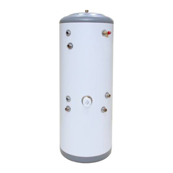
CONNECTIONS AND CONTROLS 21 22 Figure 2-4: Grant QRSC and QRSCSL cylinders Figure 2-5: Grant QRTC cylinders Table 2-10: Grant QR indirect heat pump cylinder connections and controls (key to Figures 2-4 and 2-5) Item Description Connection Size Item Description... -
Page 13: Optional Plinth Dimensions
OPTIONAL PLINTH DIMENSIONS Figure 2-6: Grant QR Cylinder Plinth (product code: MB-24) R 275 Figure 2-7: Grant QR Cylinder Plinth dimensions Section 2: Technical Data Page 13... -
Page 14: Primary Circuit Installation
Twin Coil cylinder, a high temperature rated solenoid valve depends on the type of heat source used with the indirect coil. (contact Grant UK for details) may need to be fitted to the solar Refer to Sections 3.3.1 and 3.3.2, as appropriate. -
Page 15: Solar Thermal System Schematics
Description This drawing and its content is subject to copyright. Use other than for its original intended purpose must be arranged with an employee of Grant UK Ltd. Hopton House, Hopton Industrial Estate, Devizes, Wiltshire, SN10 2EU, tel; 01380 736920... -
Page 16: Secondary Circuit Installation
The manifold can be installed in any position as long as it is 11. The cylinder must be registered with Grant UK within 30 days installed in the correct flow direction. Refer to the arrows on of installation. -
Page 17: Expansion Vessel
The expansion vessel must be positioned with the SECONDARY RETURN connection point at the bottom. Grant QR indirect heat pump cylinders with a storage volume of No valve should be fitted between the expansion vessel 210 litres and over are fitted with a secondary return connection. If and the cylinder. -
Page 18: Tundish
TUNDISH ! NOTE ! A suitable tundish is supplied loose with the cylinder for fitting in the common discharge pipe from the T&P and Expansion relief valves. The discharge will consist of scalding water and steam. The tundish should be vertical, located in the same space as Asphalt, roofing felt and non-metallic rainwater goods may the unvented hot water cylinder and be fitted as close to, and be damaged by such discharges. -
Page 19: Discharge Pipe Arrangement
4.13 DISCHARGE PIPE ARRANGEMENT Safety device (e.g. temperature relief valve) Metal discharge pipe from safety device 600mm max Tundish Discharged below fixed grating Fixed grating Metal discharge pipe from tundish with continuous fall. See table and worked example on previous page Trapped gully Figure 4-3: Typical discharge pipe arrangement Section 4: Secondary Circuit Installation... -
Page 20: Electrical
13 amp and contact IMMERSION HEATER separation of at least 3mm. All Grant QR indirect heat pump cylinders are supplied factory- Use 85°C heat resistant rubber insulated HOFR sheathed flexible fitted with one 3kW immersion heater. This immersion heater cable, with minimum cross sectional area of 1.5mm², to comply... -
Page 21: Immersion Heater Safety Cut-Out
Wait until the temperature has fallen sufficiently. Then Investigate If a Grant QR Twin Coil indirect heat pump cylinder is being and identify the cause of the cut-out operation and rectify the fault. installed with a solar thermal system, a high temperature 2-port solenoid valve may be required. -
Page 22: Wiring Diagrams
Any demand from the Grant HPIDTM4 DHW Timer and cylinder thermostat for hot water will activate the relay, immediately interrupting any heating demand from the Grant NeoStat. This will remain interrupted until the demand for hot water stops - either the cylinder thermostat is satisfied or there is no hot water output from the timer. - Page 23 Earth and some Neutral connections have been excluded for clarity. Grant GSX1 Solar Controller Mains Side Sensor Side 230V AC max. 12V DANGER CAUTION Cylinder bottom sensor Collector sensor Wiring Centre 11 12 Solar Pump Brown Blue Green/Yellow Brown Link...
- Page 24 50HZ Dual Thermostat ! NOTE ! ! NOTE ! Project Title: Grant Sahara Solar Thermal System, GSX1, Solenoid Valve NOT used Wiring Diagram Power supply for Solar Thermal control system to be taken The wiring diagram shown in Figure 5-4 corresponds to the from same supply as heating system controls.
-
Page 25: Commissioning, Draining Down And Safety
COMMISSIONING, DRAINING DOWN AND SAFETY IMMERSION HEATER SAFETY CUT-OUT ! NOTE ! The immersion heater incorporates an independent non self- resetting over temperature cut-out device to prevent excessive water temperatures. Refer to Section 5.3 for further details. Commissioning details should be entered in the The safety cut-out will operate if: commissioning and service log at the back of these The wiring is incorrect. -
Page 26: Cold Water Discharge From Tundish
COLD WATER DISCHARGE CUSTOMER HANDOVER FROM TUNDISH Complete the commissioning and service log at the back of these instructions and leave the instructions with the user. There are two reasons why cold water will discharge from the tundish: Explain the operation of the system to the User, referring to Section 12 of these instructions. -
Page 27: Maintenance
Servicing and maintenance must only be carried out by Remove the un-sprung circlip retaining the expansion relief a competent unvented hot water installer, or by Grant valve cartridge in the inlet manifold body. See Figure 4-1. Engineering (UK) Limited authorised personnel. -
Page 28: Fault Finding
FAULT FINDING INTERMITTENT WATER DISCHARGE Intermittent water discharge from T&P valve Expansion vessel charge Thermostat failure reduced Test vessel and recharge or Immersion thermostat failure Primary cylinder thermostat Faulty T&P valve replace Repair or replace immersion Repair or replace thermostat Replace T&P valve thermostat Test for correct operation. -
Page 29: No Flow From Hot Water Taps
NO FLOW FROM HOT WATER TAPS No flow from hot water taps Check any in-line strainers which may be fitted to the Mains supply disconnected? system and clean as required Open supply valve or wait for supply to be reconnected Test for correct operation. -
Page 30: Excessive Hot Water From Taps
EXCESSIVE HOT WATER FROM TAPS Excessive hot water from taps Is cylinder thermostat set too Correct wiring as per Is system wiring correct? high? instructions? Is cylinder thermostat Reduce thermostat setting Replace cylinder thermostat operating? Does motorised valve close Repair or replace motorised when thermostat satisfied? valve motor Repair or replace motorised... -
Page 31: Spare Parts
SPARE PARTS SPARE PARTS Table 9-1: Grant QR indirect HP cylinders - spare parts Product description Product code Inlet manifold c/w 3 bar pressure reducing valve and 6 bar expansion relief valve GCS07 Expansion relief valve - 6 bar GCS08 ½ʺ... -
Page 32: 10 Product Fiche
11 END OF LIFE INFORMATION GENERAL Grant hot water storage cylinders incorporate components manufactured from a variety of different materials. The majority of these materials can be recycled whilst the smaller remainder cannot. Materials that cannot be recycled must be disposed of according to local regulations using appropriate waste collection and/or disposal services. -
Page 33: 12 User Instructions
IMMERSION HEATERS Valve (EV) on the cylinder seek expert advice immediately. Your Grant QR indirect heat pump cylinder is fitted with one 3kW If the water is flowing from the T&P Valve, immediately: immersion heater. Refer to Section 5.1 for further details. -
Page 34: 13 Guarantee
13 GUARANTEE You are now the proud owner of a cylinder from Grant Free of charge repairs Engineering (UK) Limited, which has been designed to give you During the two year guarantee period no charge for parts years of reliable, trouble free operation. - Page 35 • The balance of the guarantee is transferable providing the installation is serviced prior to the dwelling’s new owners taking up residence. Grant Engineering (UK) Limited must be informed of the new owner’s details. • The Company will endeavour to provide prompt service in the unlikely event of a problem occurring, but it cannot be held responsible for any consequences of delay however caused.
-
Page 36: Installation, Commissioning And
APPENDIX A INSTALLATION, COMMISSIONING AND SERVICE RECORD LOG BOOK Customer Details Customer Name Customer Address TEL No. ! NOTE ! This Log Book is only for use in Great Britain. Please, keep the Log Book in a safe place for future reference. This Log Book is to be completed in full by the competent person(s) who commissioned the equipment and then handed to the customer. - Page 37 ! NOTE ! IT IS THE RESPONSIBILITY OF THE INSTALLER TO COMPLETE THIS LOGBOOK AND PASS IT ON TO THE CUSTOMER, FAILURE TO DO SO MAY INVALIDATE THE CYLINDER GUARANTEE. Appliance and Time Control Details GRANT UK Manufacturer Model Capacity Litres Serial No.
- Page 38 Hot Water System Information □ Does the hot water system comply with the appropriate Building Regulations? YES □ Has the system been installed and commissioned in accordance with the manufacturer’s instructions? YES □ Have you demonstrated the operation of the system controls to the customer? YES □...
- Page 39 SERVICE INTERVAL RECORD It is recommended that your hot water system is serviced regularly and that your service engineer completed the appropriate Service Interval Record below. ! NOTE ! SERVICE PROVIDER Before completing the appropriate Service Record below, please ensure you have carried out the service as described in the manufacturer’s instructions and in compliance with all relevant codes of practice.
- Page 40 GRANT ENGINEERING (UK) LIMITED Hopton House, Hopton Industrial Estate, Devizes, Wiltshire, SN10 2EU Tel: +44 (0)1380 736920 Fax: +44 (0)1380 736991 Email: info@grantuk.com www.grantuk.com...
Need help?
Do you have a question about the QR Range and is the answer not in the manual?
Questions and answers