Table of Contents
Advertisement
Owner's Manual
G A S O L I N E G E N E R A T O R
This manual provides information regarding the operation and maintenance of these
products. We have made every effort to ensure the accuracy of the information in this manual.
We reserve the right to change this product at any time without prior notice.
Please keep this manual available to all users during the entire life of the generator.
Advertisement
Table of Contents

Related Manuals for PowerLand PD2000


Summary of Contents for PowerLand PD2000
- Page 1 Owner's Manual G A S O L I N E G E N E R A T O R This manual provides information regarding the operation and maintenance of these products. We have made every effort to ensure the accuracy of the information in this manual. We reserve the right to change this product at any time without prior notice.
-
Page 2: Specifications
SPECIFICATIONS Item PD2000 PD4000E PD6500E Rated Wattage 1200 W 3200 W 5500 W Surge Wattage 1500 W 4000 W 5500 W Rated Voltage 120 V 120/240 V Rated Frequency 60 Hz Phase Single DC Output DC 12V/8.3 A Engine type... - Page 3 The engine exhaust from this product contains chemicals known to the State of California to cause cancer, birth defects or other reproductive harm. WARNING: The generator is a potential source of electrical shock if misused. Do not expose the generator to moisture, rain or snow. Do not let the generator get wet, and do not operate it with wet hands.
-
Page 4: Table Of Contents
CONTENTS SAFETY ......……………………………………………………………………..1 Safety Label Locations ...... …………………………………………………..1 Safety Information ......…………………………………………………………..1 COMPONENT IDENTIFICATION ......…………………………………………………3 CONTROLS ....…………………………………………………………………………..4 Engine Switch ....………………………………………………………………………..4 Recoil Starter ………………………………………………………....... ……..…4 Fuel Valve Lever ……………………………………………………………………………………4 Choke Rod ..…………………………………………………………………………………..5 Voltage Selector Switch (Dual Voltage System) ....………………………....5 Ground Terminal ................ -
Page 5: Safety
SAFETY SAFETY LABEL LOCATIONS These labels warn you of potential hazards that can cause serious injury. Read them carefully. If a label comes off or becomes hard to read, contact your Generator dealer for a replacement. SAFETY INFORMATION Our generators are designed to give safe and dependable service if operated according to instructions. - Page 6 Fire and Burn Hazards ·The exhaust system gets hot enough to ignite some materials. — Keep the generator at least 1 meter (3 feet) away from buildings and other equipment during operation. — Do not enclose the generator in any structure. —...
-
Page 7: Component Identification
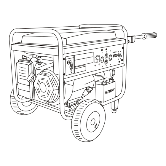
COMPONENT IDENTIFICATION Record the engine and frame serial numbers for your future reference. Refer to these serial numbers when ordering parts, and when making technical or warranty inquiries. -
Page 8: Controls
CONTROLS Engine Switch To start and stop the engine Switch position: OFF: To stop the engine. Key can be removed/inserted. To run the engine after starting. START: To start the engine by operating the starter motor. START ENGINE SWITCH ENGINE SWITCH Recoil Starter To start the engine, pull the starter grip lightly until resistance is felt, then pull briskly. -
Page 9: Choke Rod
Choke Rod The choke is used to provide an enriched fuel mixture when starting a cold engine. It can be opened and closed by operating the choke rod manually. Pull the rod out toward CLOSED to enrich the mixture for cold starting. CHOKE ROD CHOKE ROD OPEN... -
Page 10: Ground Terminal
Ground Terminal The generator ground terminal is connected to the frame of the generator, the metal non-current-carrying parts of the generator, and the ground terminals of each receptacle. Before using the ground terminal, consult a qualified electrician, electrical inspector or local agency having jurisdiction for local codes or ordinances that apply to the intended use of the generator. -
Page 11: Ac Circuit Breaker
AC Circuit Breaker The circuit breaker will automatically switch OFF if there is a short circuit or a significant overload of the generator at the receptacle. If the circuit breaker is switched OFF automatically, check that the appliance is working properly and does not exceed the rated load capacity of the circuit before switching the circuit breaker ON again. -
Page 12: Generator Use
GENERATOR USE Connections to a Building Electrical System Connections for standby power to a building electrical system must be made by a qualified electrician. The connection must isolate the generator power from utility power, and must comply with all applicable laws and electrical codes. A transfer switch, which isolates generator power from utility power, is available through authorized Honda generator dealers. -
Page 13: Ac Receptacle Selection
With the voltage selector switch in the ‘‘120/240V’’ position, you can use the 120V and 120/240V receptacles simultaneously. If you are NOT using the 120/240V receptacle, but require more power from the 120V locking plug receptacle, then select the ‘‘120V ONLY’’ position. -
Page 14: Dc Operation
DC Operation The DC terminals may ONLY be used for charging 12 volt automotive type batteries. Connecting the battery cables: 1. Before connecting the battery charging cables to a battery that is installed in a vehicle, disconnect the vehicle ground battery cable from the battery negative (-) terminal. WARNING: The battery gives off explosive gases;... -
Page 15: High Altitude Operation
High Altitude Operation At high altitude, the standard carburetor air/fuel mixture will be too rich. Performance will decrease, and fuel consumption will increase. A very rich mixture will also foul the spark plug and cause hard starting. Operation at an altitude that differs from that at which this engine was certified, for extended periods of time, may increase emissions. -
Page 16: Pre-Operation Check
PRE-OPERATION CHECK Engine oil NOTICE: Engine oil is major affecting engine performance and service life. Non-detergent and 2-stroke engine oils will damage the engine and not recommended. Check the oil level BEFORE EACH USE with the generator on a level surface with the engine stopped. -
Page 17: Fuel Recommendation
Fuel 1. Check the fuel level gauge, and refill the tank if the fuel level is low. 2. Refuel carefully to avoid spilling fuel. Do not fill above the shoulder of the fuel strainer. WARNING: Gasoline is highly flammable and explosive, and you can be burned or seriously injured when refueling. - Page 18 Oxygenated Fuels Some conventional gasoline are being blended with alcohol or an ether compound. These gasoline are collectively referred to as oxygenated fuels. To meet clean air standards, some areas of the United States and Canada use oxygenated fuels to help reduce emissions. If you use an oxygenated fuel, be sure it is unleaded and meets the minimum octane rating requirement.
-
Page 19: Starting The Engine/Stopping The Engine
STARTING THE ENGINE/STOPPING THE ENGINE Starting the Engine 1. Make sure that the AC circuit breaker is in the OFF position. The generator may be hard to start if a load is connected. 2. Turn the fuel valve lever to the ON position. 3. -
Page 20: Maintenance
MAINTENANCE The Importance of Maintenance Good maintenance is essential for safe, economical, and trouble-free operation. It will also help reduce air pollution. WARNING: Improper maintenance, or failure to correct a problem before operation, can cause a malfunction in which you can be seriously hurt or killed. Always follow the inspection and maintenance recommendations and schedules in this owner's manual. -
Page 21: Emission Control System Information
● Read the instructions before you begin, and make sure you have the tools and skills required. ● To reduce the possibility of fire or explosion, be careful when working around gasoline. Use only a nonflammable solvent, not gasoline, to clean parts. Keep cigarettes, sparks, and flames away from all fuel-related parts. -
Page 22: Air Index
Replacement Parts The emission control systems on your our engine were designed, built, and certified to conform with EPA and California emission regulations. We recommend the use of genuine our parts whenever you have maintenance done. These original-design replacement parts are manufactured to the same standards as the original parts, so you can be confident of their performance. -
Page 23: Maintenance Schedule
Maintenance Schedule (3) REGULAR SERVICE PERIOD First Every Every Every Before month 3 month 6 month year ITEM Perform at every indicated month each operating hour interval, 12 Hrs 50 Hrs 100 Hrs 300 Hrs whichever comes first 〇 · Check level Engine oil 〇... -
Page 24: Air Cleaner Service
UPPER LEVEL OIL DRAIN PLUG Wash your hands with soap and water after handling used oil. Please dispose of used motor oil in a manner that is compatible with the environment. We suggest you take it in a sealed container to your local service station or recycling center for reclamation. -
Page 25: Fuel Sediment Cup Cleaning
Fuel Sediment Cup Cleaning The sediment cup prevents dirt or water which may be in the fuel tank from entering the carburetor. If the engine has not been run for a long time, the sediment cup should be cleaned. 1. Turn the fuel valve lever to the OFF position. Remove the sediment Cup, O-ring, and filter. 2. -
Page 26: Spark Arrester Maintenance
5. Measure the plug gap with a feeler gauge. Correct as necessary by carefully bending the side electrode. The gap should be: 0.028-0.031 in (0.70--0.80 mm) 0.028-0.031 in (0.70-0.80mm ) SPARK PLUG WRENCH PLUG CAP 7. Check that the spark plug washer is in good condition, and thread the sparkplug in by hand to prevent cross-threading. -
Page 27: Transporting/Storage
TRANSPORTING STORAGE When transporting the generator, turn the engine switch and the fuel valve OFF and keep the generator level to prevent fuel spillage. Fuel vapor or spilled fuel may ignite. WARNING: Contact with a hot engine or exhaust system can cause serious burns or fires. - Page 28 Storage Procedure 1. Drain the carburetor by loosening the drain screw. Drain the gasoline into a suitable container. WARNING: Gasoline is extremely flammable and is explosive under certain conditions. Perform this task in a well ventilated area with the engine stopped. Do not smoke or allow flames or sparks in the area during this procedure.
-
Page 29: Assembly
ASSEMBLY The Importance of Proper Assembly Proper assembly is essential to operator safety and the reliability of the machine. Any error or oversight made by the person assembling and servicing a unit can easily result in faulty operation, damage to the machine, or injury to the operator. WARNING: Improper assembly can cause an unsafe condition that can lead to serious injury or death. -
Page 30: Troubleshooting
TROUBLESHOOTING Problem Cause Solution Engine switch is set to “off”. Set engine switch to “on”. Fuel valve is turned to “closed”. Turn fuel valve to “open” position. Choke is open. Close the choke Engine is out of gas. Add gas. Engine filled with... - Page 31 Change the AVR...
-
Page 32: Wiring Diagram
WIRING DIAGRAM PD2000... - Page 33 PD4000E...
- Page 34 PD6500E...
- Page 35 PD8500E...
- Page 36 PD10000E...
Need help?
Do you have a question about the PD2000 and is the answer not in the manual?
Questions and answers