Advertisement
Table of Contents
- 1 Safety Information
- 2 Table of Contents
- 3 Wattage Reference Chart
- 4 Specifications
- 5 Wiring Diagram
- 6 Assembly
- 7 Pre-Operation Check
- 8 Starting the Engine/Stopping the Engine
- 9 Operating Instructions
- 10 Maintenance
- 11 Storage
- 12 Troubleshooting
- 13 Generator Assembly and Mounting
- Download this manual
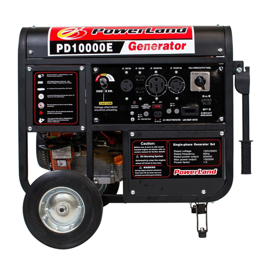
Owner's Manual
Full Power Output Panel
10000 WATT GASOLINE 16HP
This manual provides information regarding the operation and maintenance of these
products. We have made every effort to ensure the accuracy of the information in this
manual. We reserve the right to change this product at any time without prior notice.
Please keep this manual available to all users during the entire life of the generator.
Advertisement
Table of Contents

Related Manuals for PowerLand PD10000E


Summary of Contents for PowerLand PD10000E
- Page 1 Owner’s Manual Full Power Output Panel 10000 WATT GASOLINE 16HP This manual provides information regarding the operation and maintenance of these products. We have made every effort to ensure the accuracy of the information in this manual. We reserve the right to change this product at any time without prior notice. Please keep this manual available to all users during the entire life of the generator.
- Page 2 The generator is a potential source of electrical shock if misused. Do not expose the generator to moisture, rain or snow. Do not let the generator get wet, and do not operate it with wet hands. These labels warn you of potential hazards that can cause serious injury. Read them carefully.
-
Page 3: Safety Information
SAFETY INFORMATION Read and understand this instruction manual before operating your generator. You can help prevent accidents by being familiar with your generator’s controls, and by observing safe operating procedures. Operator Responsibility Know how to stop the generator quickly in case of emergency. Under stand the use of all generator controls, output receptacles, and connections. -
Page 4: Table Of Contents
CONTENTS SAFETY INFORMATION……………………………………………………………..2 COMPONENT IDENTIFICATION…………..…………………………………….…4 WATTAGE REFERENCE CHART……..………………………………………….….7 SPECIFICATIONS…………………………………………….………………….……9 WIRING DIAGRAM………………………………………………………….……..…10 ASSEMBLY………………………………………………………..……………….……11 PRE-OPERATION CHECK……………………………………………………...…….11 STARTING THE ENGINE/STOPPING THE ENGINE………………..…….………12 OPERATING INSTRUCTIONS………………………………………….…….……...13 MAINTENANCE…………………………………………..…………………….………16 STORAGE…………………………………………………..……………………………19 TROUBLESHOOTING…………………………………..……………………………..21 WARRANTY SERVICE INFORMATION……………………………..………….…..22... - Page 6 Engine Key To start and stop the engine. Key position: OFF: To stop the engine. Key can be removed / inserted. ON: To run the engine after starting. START: To start the engine by operating the starter motor. Do not turn the key switch to START position when the engine is running to prevent damage of starting motor.
- Page 7 The most power will be available at the 30A 120V locking plug receptacle. Change the Voltage Selector Switch after turning the AC circuit breaker to OFF. The generator may be damaged. Ground Terminal The generator ground terminal is connected to the frame of the generator, the metal non-current-carrying parts of the generator, and the ground terminals of each receptacle.
-
Page 8: Wattage Reference Chart
WATTAGE REFERENCE CHART Electric equipment, especially engine produces strong current when being started. The table below offers reference when you connect those installations to generator. Tool or Appliance Rated* (Running) Watts Additional Surge (Starting) Watts Essentials Light Bulb-75 watt Deep Freezer Sump Pump 1200 Refrigerator/Freezer-18 Cu. -
Page 9: Specifications
SPECIFICATIONS Model PD10000E Frequency 60 HZ Generator Max.AC Output 10000 Watt Rated AC Output 8000 Watt Run Time 8 hour Model 190F Type Air Cooled, OHV, 4-Stroke Displacement 419 cc Output 16.0 HP / 3600 rpm Fuel Unleaded Gasoline Engine Fuel Tank Capacity 8.3 Gallon... -
Page 10: Wiring Diagram
WIRING DIAGRAM... -
Page 11: Assembly
ASSEMBLY Wheel Kit Installation 1 Install the axle assembly on the generator. 2 Install the two wheels on the axle shaft using the washers and flange nuts. 3 Install the two stands on the under frame using the flange nuts. Starter Cables Connection 1 Route the starter cable under the tank. - Page 12 Use 4-stroke motor oil that meets or exceeds the requirements for API service classification SJ. Always check the API SERVICE label on the oil container to be sure it includes the letter SJ. SAE 10W-30 is recommended for general, all-temperature use. Other viscosities shown in the chart may be used when the average temperature in your area is within the indicated range.
-
Page 13: Starting The Engine/Stopping The Engine
STARTING THE ENGINE / STOPPING THE ENGINE Starting the Engine Make sure that the AC circuit breaker is in the OFF position. The generator may be hard to start if a load is connected. 2 Turn the fuel valve lever to the ON position. 3 The choke will be closed if the engine is cold, pull the choke rod out to the CLOSED position. - Page 14 Before connecting an appliance or power cord to the generator: Make sure that it is in good working order. Faulty appliances or power cords can create a potential for electrical shock. If an appliance begins to operate abnormally, becomes sluggish or stops suddenly, turn it off immediately.
- Page 15 DC Operation The DC terminals may ONLY be used for charging 12 volt automotive type batteries. Connecting the battery cables: 1 Before connecting the battery charging cables to a battery that is installed in a vehicle, disconnect the vehicle ground battery cable from the battery negative (-) terminal. The battery gives off explosive gases;...
-
Page 16: Maintenance
Disconnect the other end of the positive (+) battery cable from the battery positive (+) terminal. 5 Reconnect the vehicle ground battery cable to the battery negative (-) terminal. High Altitude Operation At high altitude, the standard carburetor air/fuel mixture will be too rich. Performance will decrease, and fuel consumption will increase. - Page 17 Before First Every3 Every6 Every REGULAR SERVICE PERIOD(2) each month months months year or ITEM or 20 or 50 or 100 Performed at every indicated month or Hrs. Hrs. Hrs. operating hour interval, whichever comes first. Check ○ Engine oil ●...
- Page 18 Air Cleaner Service A dirty air cleaner will restrict air flow to the carburetor. To prevent carburetor malfunction, service the air cleaner regularly. Service more frequently when operating the generator in extremely dusty areas. Never run the generator without the air filter. Rapid engine wear will result. Unsnap the air cleaner cover clips, remove the air cleaner cover, and remove the element.
-
Page 19: Storage
1 Remove the spark plug cap. Clean any dirt from around the spark plug base. Use a spark plug wrench to remove the spark plug. Visually inspect the spark plug. Discard it if the insulator is cracked, chipped or fouled. Measure the plug gap with a feeler gauge. -
Page 20: Troubleshooting
TROUBLESHOOTING Note: Troubleshooting problems may have similar causes and solutions. PROBLEM POSSIBLE CAUSE SOLUTION Is there fuel in the tank? Refill the fuel tank. Is there enough oil in the Add the recommended oil. engine? The engine Is the spark plug in good Readjust gap and dry the spark plug. - Page 21 EASY START INSTRUCTION 1) Apply at least 1 gallon of gas or until gas gauge shows over 2 gallons full. 2) Apply engine oil (10-30w) until you can see oil surface at the top. Apply oil cap, low oil kill switch is know activated. 3) Turn on/off switch to ON position (located on control panel).
-
Page 22: Generator Assembly And Mounting
GENERATOR ASSEMBLY AND MOUNTING Generator is supplied with a wheel kit. If you want to install the wheel kit on your unit, please follow the instructions below. If you not use the wheel kit, skip this section. 1. Place the bottom of the generator cradle on a flat, even surface. Temporarily place unit on blocks to ease assembly. - Page 23 CHANGE THE CARBON-BRUSH...
- Page 24 CHANGE THE AVR...
- Page 25 EXPLODED VIEW AND PARTS LIST...
- Page 26 Item Part Description Item Part Description Gasoline engine GB5787-86 Flange bolt M6×22 15100 Frame comp 14022 Washer 15002 Bottom rubber A 14005 Collar 15003 Bottom rubber B 14001 Cushion GB6177-86 Flange nut M8 14004 Outlet pipeφ4.5×165 GB802-88 Flange nut M6 14006 Tube clip 41350...
- Page 28 Item Part Description Item Part Description 21100 Starter comp, recoil 12012 Grommet fender GB5787-86 Flange bolt M6×8 23000 Carburetor assy. 12310 Fan, cover comp 23002 Packing, carburetor GB5787-86 Flange bolt M6×12 23001 Insulator, carburetor 19003 Shroud comp GB6177-86 Flange nut M6 12302 Clip.
- Page 29 12301 Fan cover 13106 Connecting rod assy. 121102 Cap assy. oil filler 17220 Control assy. 12230 Governor kit 17001 Spring, governor 12214 Packing, case cover 17002 Spring, throttle return 12213 Pin, dowel, 8×12 17004 Arm, governor 13100 Ping set assy. piston 17003 Rod, governor 13105...
Need help?
Do you have a question about the PD10000E and is the answer not in the manual?
Questions and answers
i need a new gas tank for my 10000 watts generator
A replacement gas tank option for the PowerLand PD10000E generator is a universal fit gas fuel tank sold under the brand "Generic" and manufactured by BMotorParts. The package contains 1 gas tank.
This answer is automatically generated