
Related Manuals for Dometic RO400


Summary of Contents for Dometic RO400
- Page 1 ReVeRse OsmOsis wateR puRifieR RO400 RO400B RO400C RO400CV RO400BC RO400BCV RO600C RO600CV WP 05 Rev. 2011-12-21 8229016-90 JON-KB 1151...
-
Page 2: Table Of Contents
(supplied with the product). This manual is valid from ..... Concerning RO400 / RO600 manufactured before this point in time, we refer to the previous version of the Service Manual. Some sections are however be more accurate in this document. -
Page 3: Service Procedures For Safety
seRViCe pROCeduRes fOR safety To prevent personal injury and/or damage to property, it is important to follow sound procedures when carrying out servicing work. The list below does not attempt to set out all such procedures, but gives some examples. •... - Page 4 CHild safety RO400a/RO400B The model name for RO400A is actually RO400 (without • Do not let children play with the water purifier. letter). The A is added in this document to distinguish from • Never leave packaging material lying around so that children RO400 when used as a family name.
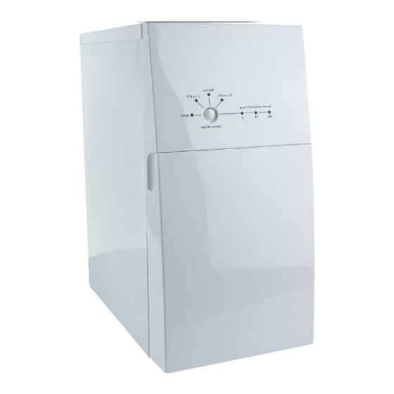
- Page 5 pROduCt OVeRView Bracket for reject water hose Reject water hose, rubber, i.d. 22 mm 10 11 12 hose clips (2) hose for inlet water, 3/4” BSP nut filter spanner Information decal control panel a) Purified water faucet * b) Connector with shut-off valve ** Purified water hose, PE 3/8”...
-
Page 6: Technical Facts
225 mm Sound level when installed <60dB(A) Weight (on delivery) 29 kg undersink cupboard Weight (filled with water) 33 kg RO400 RO600 mOdel data capacity * (at water temperature 15 °c, 750 ppm), litres/minute (± 0,5) Recommended max. usage, 1800... - Page 7 teCHniCal faCts examples of rejection for substances which may be present in water inoRGaniC suBsTanCes oRGaniC suBsTanCes Turbidity (cloudiness) >99 hydrocarbons colour rating >99 heptane, octane, decane, etc. >98 Benzene, toluene, xylene, Cations/Metals Ethyl benzene, etc. >99 Sodium >96 >92* Diesel oil >99 Potassium...
-
Page 8: Wiring And Elemantary Diagram
RO400, RO400B, RO400C, RO400BC, RO600C Orange green 1 2 3 Yellow grey 1 2 3 4 3 2 1 Black Yellow/green Blue Electronic Brown Not specified Wire colour Anti-Interference filter (RFI) capacitor chassis ground Motor floater Switch... -
Page 9: Schematic Diagram
(water) pressure sensor puRified (low pressure switch) wateR inlet valve, solenoid, with screen filter ReJeCt wateR inlet wateR RO400-models: flush valve, solenoid, normally closed (top) with Particle filter flow restrictor and activated granulated Carbon filter (gac) pressure regulating (relief) valve... -
Page 10: Product Description
pROduCt desCRiptiOn lOCate COmpOnents Shaft, common, high pressure- & loop pump Pump gable/housing Inlet valve front view, fig. a. flush valve control panel, “INDIcATOR lIghTS AND Inlet pressure sensor BUTTON” conductivity sensor front cover Outlet pressure sensor electronics and integrated prefiltration, fig. B. Pressure accumulator valve filter container I Outlet, purified water, with check valve... -
Page 11: Indicator Lights And Button
Chlorine reduction in one cartridge. The advantage of parallell flow is the lower pressure drop, which becomes more important at high water flow (RO600 compared with RO400). The finer particle filtration gives an improvement not only on the membrane service life, but also the integrated high pressure pump (e20). -
Page 12: Pump System
pROduCt desCRiptiOn pump system After the water has passed the prefilters, it passes through the high pressure pump (e20). The high pressure pump is a vane pump, belt (e18) driven by a motor (e33). The pump is mounted in a special designed pump housing (e21) in brass. The integration of several parts and components in the pump housing is the key to the compact size of the product. -
Page 13: Purified Water System
pROduCt desCRiptiOn puRified wateR system After the purified water leave the membrane pressure vessel, it pass through the pressure regulating valve (e30). This is a safety feature, to avoid high pressure to the distribution net in case of failure, and to protect the the product from water ham- mer when a valve or faucet is closed on the pure water hose. -
Page 14: Water Quality Monitoring
wateR quality mOnitORing Purified water quality is monitored continously with a conductivity sensor (e25) positioned in the water flow just before the purified water outlet. conductivity is the measure of the ability for a material to conduct electricity, in this case in water. With a high concentration of ions in the water will the conductiv- ity be high, and vice versa. -
Page 15: Low Pressure Restart
pROduCt desCRiptiOn lOw pRessuRe RestaRt This function is included only in commercial (c-) models. CAUTION In commercial applications it is common that the water purifier operates automati- when idle in restart mode, the wa- cally towards a connected external equipment. An alarm stop may cause troubles ter purifier may start unexpected. -
Page 16: Display Time In Operation
pROduCt desCRiptiOn display time in OpeRatiOn display numBeR Of lOw pRessuRe stOps The water purifier is equipped with a counter for measuring The number the water purifier stops due to low inlet pressure is the total time of water production. counted by the water purifier. -
Page 17: Service Records
seRViCe ReCORds data COlleCtiOn at installatiOn Recommended data to be collected at installation: customer name / address: Purchase date: SKU no.: Product no.: Serial no.: Installation date: 91073002 - 919240 - Remarks on inlet water quality: Inlet water temperture (ºc): Inlet flowing pressure (bar): Remarks on installation conditions: Pretreatment:... -
Page 18: Troubleshooting
tROuBlesHOOting The troubleshooting guide consists of: guide compromises the internal safety systems of the product and may also involve operation of the water purifier without The “ ” will help you to inter- lED INfORMATION gUIDE protective cover. pret the LED information shown on the product’s display. The “... - Page 19 tROuBlesHOOting indiCatiOn fault Case Remedial aCtiOn Warning about used filter. • Change filter II in accordance with REPlAcINg ThE fIlTERS • See “ , section 9. fAUlT IDENTIfIcATION TABlE” Alarm for poorer water quality. • If the water purifier is new and not yet calibrat- ed, rectify according to the section cAlIBRA- TION...
-
Page 20: Fault Identification Guide
tROuBlesHOOting fault identifiCatiOn guide This guide describes: • A number of symptoms as well as feasible solutions to these. • Special features regarding some of the symptoms. These notes, e.g. low inlet water temperature are listed in the “Comments” section following the “Fault identification table”. •... - Page 21 System pressure is 15±1 bar. and fig ...) pump failure. Total pump capacity is • Measure the capacity of the RO400: approx. 5.5 litres/minute pump by measuring the total RO600: approx. 7.7 litres/minute. flow of reject and permeate Inlet water temperature is OK. water.
- Page 22 tROuBlesHOOting possible error symptom Check/action Remedy codes The water purifier <Not displayed> does not stop even if the valve/faucet is closed. The water purifier is • check for dripping water in flushing. the pure water line located after the water purifier. (Usually a leakage in a con- nection results in intermit- tent start and stop and not a...
- Page 23 tROuBlesHOOting possible error symptom Check/action Remedy codes The water purifier The green ON/ Domestic model: Restart the product. has stopped due to OFF light is lit. commercial model: Wait for 2 minutes. 15-minute error cut The water production starts automatically out (domestic 20 min.
- Page 24 tROuBlesHOOting possible error symptom Check/action Remedy codes The motor is broken. • check if the motor starts. change the PcB. If this does not solve the problem, put the old PcB back and then, • check the wiring and con- replace the motor.
- Page 25 tROuBlesHOOting possible error symptom Check/action Remedy codes Alarm, too low pres- • Has filter I been replaced? If filter I has not been changed or if the parti- sure due to a high cle load is high, change filter I and try again. •...
- Page 26 tROuBlesHOOting possible error symptom Check/action Remedy codes • Start the water purifier. Alarm, too low pres- If the reject valve remains in a flushing check if it produces any sure due to a reject position - change the reject valve. pure water or if the flow is valve that does not very low.
- Page 27 tROuBlesHOOting possible error symptom Check/action Remedy codes Alarm, too low pres- • Verify that the connection of carefully, short circuit pin 1 and 4 at the con- sure due to a broken the inlet pressure sensor to nection of the pressure sensor on the PcB. inlet pressure sensor.
- Page 28 Flushing 2 l/min — RO400B, RO400Bc and RO400c ken reject valve. starts and allows cold water 0.8 l/min — RO400. to enter the product. Verify that the: Replace the reject valve if the reject flow is flushing commence after >...
- Page 29 tROuBlesHOOting possible error symptom Check/action Remedy codes Intermittent start and <Not displayed> stop. leakage in a section • Is the faucet/valve closed? If the problem is solved with the new valve, of the pure water the problem is most likely due to a leakage •...
- Page 30 tROuBlesHOOting possible error symptom Check/action Remedy codes 10. non-normal sound Water is not produced. • Does the motor rotate The circuit board is broken and cannot make There is rattling properly or has it stopped the motor turn properly – change circuit board. sound from the (vibrating/rattling)? motor.
-
Page 31: Comments
COmments The water flow is a function of temperature. A change of only Due to the high capacity of the RO400 models it may effect 5 °C may change flow up to 20%. the feed pressure if the net cannot supply sufficient amount of water. -
Page 32: Service
seRViCe tOOls fOR seRViCe Below listed tools, shown in fig. l, facilitates service: Inlet pressure gauge , control flowing inlet pressure 0-10 bar. hose cutter System pressure gauge , 1/8R thread and 0-25 bar meter. Tee-handle , simplifies work with the brass gable. handheld conductivity meter hose gripper peRfORming a diOde test... -
Page 33: Changing Flush Valve
seRViCe CHanging flusH ValVe The numbers within brackets refer to fig. O. Disconnect the water purifier from electricity. Remove the top cover (two screws at rear). Disconnect the wires from the flush valve ( Remove the hose clip securing the waste water hose and remove the hose (2). -
Page 34: Changing Top Section Of Prefilter Assembly
Press down the springs ( slide bar to pull out the top section. Remove the hoses from the top section. The water flow configuration differs between RO400 and RO600: a) Serial flow, RO400 Rubber hose ( 3) to the pump inlet. -
Page 35: Changing Pressure Sensors
seRViCe CHanging pRessuRe sensORs The numbers within brackets refer to fig. R. Disconnect the water purifier from electricity. Remove the top cover (two screws at rear). Remove the control panel (two screws at top and two at bottom). On the PcB, release the connection from the pressure sensor by pulling them carefully out- and upwards so that the contact unlocks. -
Page 36: Changing Purified Water Outlet
seRViCe CHanging puRified wateR Outlet Disconnect the water purifier from electricity. Remove the top cover (two screws at rear). Remove the 3/8” hose from the purified water outlet both in- and outside of the casing. Remove the plastic nut holding the purified water outlet to the casing. -
Page 37: Changing Pressure Regulating Valve
seRViCe CHanging pRessuRe Regulating ValVe The numbers within brackets refer to fig. U. Disconnect the water purifier from electricity. Remove the top cover (two screws at rear). Remove the motor assembly ( 1), see “ chANgINg MO- ”, point 3-6. Disconnect all the hoses from the pressure regulating valve (2). -
Page 38: Fitting Pump- / Membrane Service Kit
seRViCe fitting pump- / memBRane seRViCe kit The numbers within brackets refer to fig. V. Disconnect the water purifier from electricity and water supplies. Remove the top cover (two screws at rear). Remove the hoses from the backside of the product: the inlet-, reject- and purified water hose. - Page 39 seRViCe Continues from previous page cont. With the tee-hande, pull the pump/membrane assembly up (11). let most of the water drain off from the mem- brane into the vessel before taking the assembly out. Remove the spring and the end bushing ( 12) from the lower membrane gable, and put aside.
-
Page 40: Flushing
seRViCe Disconnect the water purifier from electricity. Continues from previous page Connect to electricity and the product will flush. flush the product two (2) more times by disconnect- Press down the pump/membrane assembly into the ing and reconnecting electricity. vessel so that the three sections of locking rings can New installation or membrane replacement be put in place (10). - Page 41 - 41 -...
- Page 42 Dometic holding AB Torggatan 8 SE-171 54 SOlNA Tel: +46 8 501 025 00 fax: +46 8 501 025 99 www.dometicgroup.com...
Need help?
Do you have a question about the RO400 and is the answer not in the manual?
Questions and answers