Table of Contents
Advertisement
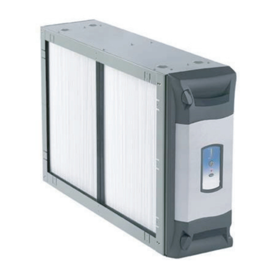
Upflow Furnace
Models
*FD145CLFR000D
*FD175CLFR000D
*FD210CLFR000D
*FD245CLFR000D
ALL phases of this installation must comply with NATIONAL, STATE AND LOCAL CODES
IMPORTANT - This Document is customer property and is to remain with this unit.
▲
WARNING
!
This information is for use by individuals having adequate
backgrounds of electrical and mechanical experience. Any
attempt to repair a central air conditioning product may
result in personal injury and/or property damage. The
manufacturer or seller cannot be responsible for the
interpretation of this information, nor can it assume any
liability in connection with its use.
© Trane 2011
Installation
Operation
Maintenance
Whole House Air Cleaner
Downflow Furnace
Models
*FD14DCLFR000D
*FD17DCLFR000D
*FD21DCLFR000D
*FD24DCLFR000D
Please return to service information pack upon completion of work.
Air Handler
Models
*FD175CLAH000D
*FD215CLAH000D
*FD235CLAH000D
*FD260CLAH000D
Contents
Electrical Connections to a COM Sys Air Handler in
Conventional 24 V Mode
Electrical Connections to a COM Sys Air Handler
Electrical Connections to a COM Sys Furnace
in 24 V Mode
Electrical Connections to a COM Sys Furnace
Electrical Connections for Dual Whole House
Air Cleaners
Pre-Filter Setting
Cell Cleaning Setting
I.
▲
WARNING
!
RISK OF ELECTRIC SHOCK: These servicing instructions
are for use by qualified personnel only. To reduce the risk
of electric shock, do not perform any servicing other than
that contained in these operating instructions unless you
are qualified to do so.
18- HE53D1- 11
50 Hz Air Handler
Models
*FD215CLAH005D
*FD235CLAH005D
*FD260CLAH005D
* May be "A" or "T"
3
3
4
5
5
5
6
7
8
10
11
12
13
14
15
17
17
17
17
18
18
18
18
18
23
26
Advertisement
Table of Contents

Subscribe to Our Youtube Channel
Related Manuals for Trane FD145CLFR000D


Summary of Contents for Trane FD145CLFR000D
-
Page 1: Table Of Contents
© Trane 2011... - Page 2 Installer’s Guide 4 4 4 4 4 3 3 3 3 3 9 9 9 9 9 5 5 5 5 5 6 6 6 6 6 8 8 8 8 8 1 1 1 1 1 2 2 2 2 2 3 3 3 3 3 7 7 7 7 7 2 2 2 2 2 1 1 1 1 1...
-
Page 3: Duct Support Installation
Installer’s Guide A. DUCT SUPPORT INSTALLATION Rafter or Joist ▲ ▲ CAUTION Supply SAFETY HAZARD Return Furnace or Plenum Plenum Air Handler Cleaner Sharp Edge Hazard. Be careful of sharp edges on equip- ment or any cuts made on sheet metal while installing or Return Air Plenum must be servicing. -
Page 4: Door Operation
Installer’s Guide Select a location that meets the following: 4. Install the air cleaner such that the airflow direction arrow on the cabinet always points towards the fur- 1. The face of the cell must be at a right angle to the air nace/ air handler. -
Page 5: Installation Guidelines
Installer’s Guide Step 2: Rotate the door to fully remove from the air Step 4: Rotate latches to secure door as shown in Figure cleaner. See Figure 11. Rotate door away from unit to remove Rotate door away from unit to remove Air Cleaner Figure 15 Door Latch Detail Figure 11 Door Rotation... -
Page 6: Downflow Furnace Installation
Installer’s Guide UPFLOW AIR HANDLER APPLICATIONS ONLY DOWNFLOW FURNACE INSTALLATION 9. Position the baffle onto the air cleaner as indi- NOTE: On 90% Downflow Furnaces, the intake and cated in Figure 17. The baffle should be posi- exhaust (flue) are located on top. A field supplied tioned on the leaving air side of the air cleaner transition is needed between the furnace and the air cabinet opposite the power door. -
Page 7: Side Return Furnace Installation
Installer’s Guide 3. On a protective pad, lay the indoor unit on its side. 4. Apply transitions or spacer as required to clear flue piping and to ensure the opening of the air cleaner Position the furnace with the return air side of the cabinet facing up. -
Page 8: Electrical Connections
• Plug the air cleaner power/control cable into the air cleaner door and route the cable into the indoor unit OTE: A 50 VA transformer is required for Trane/ low voltage wiring location. American Standard Heating & Air Conditioning •... - Page 9 Installer’s Guide Figure 22A - Wiring Diagram for 24 V Mode BLUE GREEN BROWN BLACK WHITE NOTE: The Black wire must be con- nected to chassis ground to ensure Air Handler may not have a Low Voltage Terminal board. Connect Electronic Air Cleaner wires to proper operation.
- Page 10 Installer’s Guide ELECTRICAL CONNECTIONS TO A COMMUNICATING SYSTEM AIR HANDLER IN CONVENTIONAL 24 V MODE ▲ Replace the Communicating control box cover. WARNING Locate the white wire coming from the HAZARDOUS VOLTAGE! DISCONNECT ALL ELECTRIC Communicating System Air Handler PCB labeled POWER, INCLUDING REMOTE DISCONNECTS BEFORE “EAC”.
- Page 11 Installer’s Guide ELECTRICAL CONNECTIONS TO A STANDARD 24 VOLT AIR HANDLER ▲ WARNING HAZARDOUS VOLTAGE! DISCONNECT ALL ELECTRIC POWER, INCLUDING REMOTE DISCONNECTS BEFORE SERVICING. FOLLOW PROPER LOCKOUT/TAGOUT PROCEDURES TO ENSURE THE POWER CAN NOT BE INADVERTENTLY ENERGIZED. FAILURE DISCONNECT POWER BEFORE SERVICING COULD RESULT IN DEATH OR SERIOUS INJURY.
- Page 12 Installer’s Guide ELECTRICAL CONNECTIONS TO A COMMUNICATING SYSTEMS AIR HANDLER IN COMMUNICATING MODE PROCEDURE: ▲ WARNING Remove electrical power going into the air handler. HAZARDOUS VOLTAGE! DISCONNECT ALL ELECTRIC On the communicating systems air handler, remove POWER, INCLUDING REMOTE DISCONNECTS BEFORE the blower access panel.
- Page 13 Installer’s Guide ELECTRICAL CONNECTIONS TO A COMMUNICATING FURNACE IN 24 V MODE ▲ Attach the blue wire from the air cleaner wiring harness to the WARNING open tab on the piggyback terminal supplied in the BAYACCECOMM101. Attach piggyback terminal to the 35VA HAZARDOUS VOLTAGE! DISCONNECT ALL ELECTRIC transformer terminal “C”...
- Page 14 Installer’s Guide ELECTRICAL CONNECTIONS TO A COMMUNICATING SYSTEM FURNACE Connect Red stripped wire to "R" terminal on the furnace control ▲ WARNING board. Connect Blue stripped wire to "B" terminal on the furnace control HAZARDOUS VOLTAGE! DISCONNECT ALL ELECTRIC board. POWER, INCLUDING REMOTE DISCONNECTS BEFORE Connect Brown stripped wire to "D"...
-
Page 15: Electrical Connections To An Oil Furnace
Installer’s Guide ELECTRICAL CONNECTIONS TO AN OIL FURNACE Refer to the diagrams below for proper connections ▲ WARNING to an oil furnace. Consult the oil furnace installer's HAZARDOUS VOLTAGE! DISCONNECT ALL ELECTRIC guide for additional information. POWER, INCLUDING REMOTE DISCONNECTS BEFORE SERVICING. - Page 16 Installer’s Guide ELECTRICAL CONNECTIONS FOR DUAL WHOLE HOUSE AIR CLEANER Dual Whole House Air Cleaners In some instances, two whole house air cleaners can be utilized to manage the overall system operational static pressure. The figure below shows two whole house air cleaners installed on an upflow furnace.
- Page 17 Installer’s Guide ELECTRICAL CONNECTIONS FOR DUAL WHOLE HOUSE AIR CLEANERS AND FURNACE IN CONVENTIONAL 24V MODE FIELD SUPPLIED 50 VA TRANSFORMER ELECTRICAL CONNECTIONS FOR DUAL WHOLE HOUSE AIR CLEANER AND FURNACE IN COMMUNICATING MODE FIELD SUPPLIED 75 VA TRANSFORMER Pub. No. 18-HE53D1-11 Numbers in [brackets] are for 50 Hz international systems.
-
Page 18: Air Cleaner Operation
Installer’s Guide F. AIR CLEANER OPERATION G. SET-UP MODE A combination of RED, YELLOW, and GREEN LED's are LED's used to indicate the following settings. See Figure 25. • The three GREEN LED's are used to indicate PRE- CLEAN FILTER cleaning interval. This is measured in actual run POWER time of the indoor fan. -
Page 19: Field Charger Power Level
Installer’s Guide CELL CLEANING SETTING (Figure 27) H. MAINTENANCE One or more of the YELLOW LED’s will come on indicating the COLLECTION CELL cleaning time setting. ▲ Repeatedly press the RESET button to cycle through the CAUTION time options for the COLLECTION CELL cleaning cycle until the desired setting is displayed. - Page 20 Installer’s Guide Before removing the door from the unit, remove the power The air cleaner is factory set to notify the home owner to cable plug from the socket located in the corner of the door. clean the PRE-FILTER every two months [10 weeks] of actual run time of the air cleaner.
- Page 21 Installer’s Guide 1. Using a vacuum hose, vacuum in even strokes across the entire COLLECTION CELL surface. Vacuum using even strokes in one direction, then repeat the process using even strokes in the opposite direction, as demonstrated in Figure 34. Handles Fold Flat Figure 36 Collection Cell, Handle Folded...
- Page 22 Installer’s Guide Alternate Cleaning option for homeowners with 200 • Do NOT use soap or detergent in cleaning the or 200-1 COLLECTION CELLS ONLY COLLECTION CELLS. Vacuuming the PRE-FILTER and COLLECTION CELLS • Do NOT immerse the COLLECTION CELLS restores them to a high efficiency. However, some completely in water.
-
Page 23: Fault Codes
Installer’s Guide 5. Replace the door onto the air cleaner cabinet (see NOTE: The pre-filter may also be washed ONLY if Reinstalling the Power Door, page 5). the COLLECTION CELLS show a "200/200-1". Follow the same instructions to wash the PRE- FILTER - being sure to tap gently and wipe off any visible water droplets. -
Page 24: Outline Drawings
ADD DOOR DEPTH FOR TOTAL 2.8” Side View 7-7/16 24-13/16 Front Cabinet UPFLOW FURNACE MODEL NUMBERS ifD Air Cleaner B (multiple B (one piece piece cabinet) cabinet) *FD145CLFR000D 14.5 11.9 *FD175CLFR000D 17.5 14.9 *FD210CLFR000D 21.0 18.4 18.5 *FD245CLFR000D 24.5 21.9 * May be "A"... - Page 25 Installer’s Guide Dimensions (all dimensions in inches) OUTLINE DRAWING FOR DOWNFLOW FURNACES 21” CABINET DEPTH ADD DOOR DEPTH FOR TOTAL 2.8” Side View 7-7/16 18-13/16 Front Cabinet DOWNFLOW FURNACE MODEL NUMBERS B (multiple B (one piece ifD Air Cleaner piece cabinet) cabinet) *FD14DCLFR000D 14.5...
- Page 26 Installer’s Guide Dimensions (all dimensions in inches) OUTLINE DRAWING FOR AIR HANDLERS 21” DEPTH CABINET ADD DOOR DEPTH FOR TOTAL 2.8” Side View 18.88 Front Cabinet AIR HANDLER MODEL NUMBERS B (multiple B (one piece ifD Air Cleaner piece cabinet) cabinet) *FD175CLAH000D 17.5...
-
Page 27: Pressure Drop Information
J. PRESSURE DROP INFORMATION PRESSURE DROP AT SPECIFIC AIRFLOW PER MODEL 400 CFM 600 CFM 800 CFM 1000 CFM 1200 CFM 1400 CFM 1600 CFM 1800 CFM 2000 CFM *FD145CLFR000D 0.06 0.10 0.16 0.23 0.30 *FD175CLFR000D 0.05 0.08 0.12 0.17 0.22... - Page 28 Installer’s Guide Trane 07/11 6200 Troup Hwy. Tyler, TX 75707 The manufacturer has a policy of continuous product and product data improvement and reserves the For more information contact your local dealer (distributor) right to change design and specifications without notice.
Need help?
Do you have a question about the FD145CLFR000D and is the answer not in the manual?
Questions and answers