Advertisement
Service Facts
Upflow Furnace Models
*FD145CLFR000D
*FD175CLFR000D
*FD210CLFR000D
*FD245CLFR000D
ALL phases of this installation must comply with NATIONAL, STATE AND LOCAL CODES
IMPORTANT — This Document is customer property and is to remain with this unit.
1
9 9 9 9 9
3 3 3 3 3
1 1 1 1 1
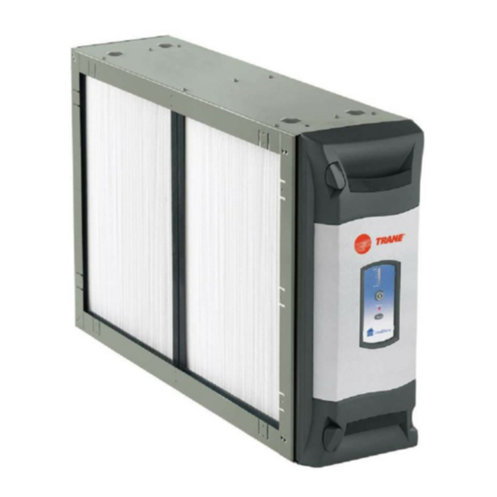
1) PRE-FILTER - traps large particles such as hair and lint before
they can enter the COLLECTION CELL section.
2) FIELD CHARGER - Charges the contaminants. Only to be
serviced by a qualified technician.
3) COLLECTION CELL (2) - removes and collects very small
impurities from the air.
4) CABINET - mounts between the furnace/air handler and return
air duct work and houses the COLLECTION CELLS, FIELD
CHARGER and PRE-FILTER.
5) POWER DOOR - the solid state power supply components
that convert the 24 Volt AC to the high-voltage, direct current
required to power the FIELD CHARGER and COLLECTION
▲
WARNING
!
This information is for use by individuals having adequate
backgrounds of electrical and mechanical experience. Any
attempt to repair a central air conditioning product may re-
sult in personal injury and/or property damage. The manu-
facturer or seller cannot be responsible for the interpreta-
tion of this information, nor can it assume any liability in con-
nection with its use.
© Trane 2011
Whole House Electronic Air Cleaner
Downflow Furnace Models
*FD14DCLFR000D
*FD17DCLFR000D
*FD21DCLFR000D
*FD24DCLFR000D
Please return to service information pack upon completion of work.
4 4 4 4 4
3 3 3 3 3
Air Handler Models
*FD175CLAH000D
*FD215CLAH000D
*FD235CLAH000D
*FD260CLAH000D
COMPONENTS OF THE AIR CLEANER
5 5 5 5 5
6 6 6 6 6
7 7 7 7 7
2 2 2 2 2
CELLS. Allows access to the COLLECTION CELLS, FIELD
CHARGER and PRE-FILTER.
6) TRANSFORMER - supplies 24 Volts to the indoor unit and Air
Cleaner (not available with 50 Hz units)
7) 24 VOLT POWER / CONTROL CABLE
8) GASKET, LITERATURE AND HARDWARE PACKET
9) UPFLOW AIR HANDLER BAFFLE - This baffle is only included
with Air Handler models. See note below.
NOTE: Be careful not to discard the baffle. It is located under
the collection cells in the shipping box.
RECONNECT ALL GROUNDING DEVICES.
All parts of this product that are capable of conducting elec-
trical current are grounded. If grounding wires, screws,
straps, clips, nuts, or washers used to complete a path to
ground are removed for service, they must be returned to their
original position and properly fastened.
EAC- SF- 1 3
50 Hz Air Handler Models
TFD215CLAH005D
TFD235CLAH005D
TFD260CLAH005D
* May be "A" or "T"
8 8 8 8 8
1 1 1 1 1 2 2 2 2 2 3 3 3 3 3
AIR
FLOW
▲
CAUTION
!
Advertisement
Table of Contents

Subscribe to Our Youtube Channel
Related Manuals for Trane FD145CLFR000D Series


Summary of Contents for Trane FD145CLFR000D Series
- Page 1 © Trane 2011...
-
Page 2: Modes Of Operation
OTE: A 50 VA transformer is required for Trane/ • Connect the power/control wiring per Figure 2. American Standard Heating & Air Conditioning NOTE: For non-Trane/American Standard Heating &... - Page 3 Wiring Diagram 2 2 2 2 2 Communicating Mode BLUE BLUE BLUE GREEN GREEN Unused BROWN BROWN GREEN BLACK BLACK WHITE WHITE BROWN Data Line BROWN WHITE BLACK NOTE: The Black wire must be Unused connected to chassis ground to Air Handler may not have a Low Voltage Terminal board.
- Page 4 Service Facts ELECTRICAL CONNECTIONS TO A COMMUNICATING SYSTEM AIR HANDLER IN CONVENTIONAL 24 V MODE ▲ Replace the Communicating control box cover. WARNING Locate the white wire coming from the HAZARDOUS VOLTAGE! DISCONNECT ALL ELECTRIC Communicating System Air Handler PCB labeled POWER, INCLUDING REMOTE DISCONNECTS BEFORE “EAC”.
- Page 5 Service Facts ELECTRICAL CONNECTIONS TO A STANDARD 24 VOLT AIR HANDLER ▲ WARNING HAZARDOUS VOLTAGE! DISCONNECT ALL ELECTRIC POWER, INCLUDING REMOTE DISCONNECTS BEFORE SERVICING. FOLLOW PROPER LOCKOUT/TAGOUT PROCEDURES TO ENSURE THE POWER CAN NOT BE INADVERTENTLY ENERGIZED. FAILURE DISCONNECT POWER BEFORE SERVICING COULD RESULT IN DEATH OR SERIOUS INJURY.
- Page 6 Service Facts ELECTRICAL CONNECTIONS TO A COMMUNICATING SYSTEMS AIR HANDLER IN COMMUNICATING MODE PROCEDURE: ▲ WARNING Remove electrical power going into the air handler. HAZARDOUS VOLTAGE! DISCONNECT ALL ELECTRIC On the communicating systems air handler, remove POWER, INCLUDING REMOTE DISCONNECTS BEFORE the blower access panel.
- Page 7 Service Facts ELECTRICAL CONNECTIONS TO A COMMUNICATING FURNACE IN 24 V MODE ▲ Attach the blue wire from the air cleaner wiring harness to the WARNING open tab on the piggyback terminal supplied in the BAYACCECOMM101. Attach piggyback terminal to the 35VA HAZARDOUS VOLTAGE! DISCONNECT ALL ELECTRIC transformer terminal “C”...
- Page 8 Service Facts ELECTRICAL CONNECTIONS TO A COMMUNICATING SYSTEM FURNACE Connect Red stripped wire to "R" terminal on the furnace control ▲ WARNING board. Connect Blue stripped wire to "B" terminal on the furnace control HAZARDOUS VOLTAGE! DISCONNECT ALL ELECTRIC board. POWER, INCLUDING REMOTE DISCONNECTS BEFORE Connect Brown stripped wire to "D"...
- Page 9 Service Facts ELECTRICAL CONNECTIONS TO AN OIL FURNACE Refer to the diagrams below for proper connections ▲ WARNING to an oil furnace. Consult the oil furnace installer's HAZARDOUS VOLTAGE! DISCONNECT ALL ELECTRIC guide for additional information. POWER, INCLUDING REMOTE DISCONNECTS BEFORE SERVICING.
- Page 10 Service Facts ELECTRICAL CONNECTIONS FOR DUAL WHOLE HOUSE AIR CLEANER Dual Whole House Air Cleaners In some instances, two whole house air cleaners can be utilized to manage the overall system operational static pressure. The figure below shows two whole house air cleaners installed on an upflow furnace.
- Page 11 Service Facts ELECTRICAL CONNECTIONS FOR DUAL WHOLE HOUSE AIR CLEANERS AND FURNACE IN CONVENTIONAL 24V MODE FIELD SUPPLIED 50 VA TRANSFORMER ELECTRICAL CONNECTIONS FOR DUAL WHOLE HOUSE AIR CLEANER AND FURNACE IN COMMUNICATING MODE FIELD SUPPLIED 75 VA TRANSFORMER EAC-SF-13 Numbers in [brackets] are for 50 Hz international systems.
-
Page 12: Air Cleaner Operation
Service Facts SET-UP MODE OF OPERATION DIRTY LEDs To enter the SET-UP mode press and hold both the POWER and RESET buttons for a minimum of 5 [6] seconds. The CLEAN display will go blank and then the factory settings for each of POWER the settings are displayed. -
Page 13: Fault Codes
Service Facts or the COLLECTION CELLS need to be cleaned. The Air NOTE: If two air cleaners are connected on the same system, set all timers on both air cleaners to the same Cleaner control has detected ten consecutive automatic High settings. - Page 14 Service Facts ifD™ DISPLAY FAULT LED CODES COMFORT AIR-CLEANER CONTROL ERROR FAULT DESCRIPTION YEL-1 YEL-2 YEL-3 YEL-4 RED-1 RED-2 RED-3 SERVICE PROCEDURE COM LED CODE Repower Air Cleaner - check for normal Internal control lockout Device Count operation. Replace door if same fault comes Duplicate Filter, Another filter timer is present/ Only seen when Air Cleaner is configured...
-
Page 15: System Information
Service Facts Do not remove the door until all of the lights are off. ▲ WARNING Disconnect the power /control cable. Rotate the two latches and remove the door as shown in RISK OF ELECTRIC SHOCK: These servicing instructions Figure 10. Place the door in a secure location. are for use by qualified personnel only. - Page 16 Service Facts The Air Cleaner is factory set to notify the homeowner to clean the PRE-FILTER every two months [10 weeks] of actual run time of the Air Cleaner. This notification can be changed by the installer/homeowner to 1 month [5 weeks] or 3 months [15 weeks] depending on the conditions in the home (pets, smokers, etc.).
- Page 17 Service Facts Handles Fold Flat 3. Replace the power door onto the Air Cleaner. 4. Ensure the power cord is plugged into the Air Cleaner. A steady amber light indicates that the unit is wired in the 24 V mode. A blinking amber light indicates that the unit is wired in the...
- Page 18 Service Facts NOTE: Once you press the POWER button, the first LED will be on and it will start flashing after the first 10 [12] minutes of indoor fan operation. This is normal operation. 7. On the thermostat, reset the indoor fan operation to the desired mode.
- Page 19 Service Facts If all three are NOT on, press the POWER button three 6. Rotate the styrofoam block on the FIELD CHARGER Pin. times and then press the RESET button until you get all three Red LEDs on. Now press and hold both the POWER button and the RESET button for five seconds then release these buttons to leave the SET-UP mode.
-
Page 20: Pressure Drop
Service Facts instructions). The top three Red LEDs should be on for this test. The three Red LEDs being on indicates that the Air Cleaner Power level setting is set at the Maximum / 9.6 KV position. If all three are NOT on, press the POWER button three times and then press the RESET button until you get all three Red LEDs on. -
Page 21: Troubleshooting
Service Facts TROUBLESHOOTING Service Indications Service Checks Indoor Blower ON/ Air Cleaner First Green LED OFF 1. Check that the Power Door is installed correctly and the latches closed. The actuator tab must engage the door safety switch. 2. Check the air cleaner power/control cable. 3. - Page 22 Service Facts COMPONENT FAILURE EVALUATION Component Failure Evaluation This whole house air cleaner can be installed either as part of a communicating system or as part of a traditional 24 volt system Is the amber light above the power cord connection on continuously 24VAC Mode COM Mode...
- Page 23 Service Facts Component Failure Evaluation in 24 Volt Mode Remove the Door panel has power door, Reinstall power yellow or red collection cells, door to air cleaner flashing LEDs and field charger Power the air Bypass the 10 minute cleaner with time delay (This is 24VAC and done by entering and...
- Page 24 Clear fault log operating correctly. Clear fault log 07/11 Trane 6200 Troup Highway Tyler, TX 75707 Since the manufacturer has a policy of continuous product and product data improvement, it reserves the right For more information contact your local dealer (distributor)
Need help?
Do you have a question about the FD145CLFR000D Series and is the answer not in the manual?
Questions and answers