Digiever DS-2005 User Manual
Hide thumbs
Also See for DS-2005:
- User manual (347 pages) ,
- Quick installation manual (9 pages) ,
- User manual (217 pages)

Related Manuals for Digiever DS-2005


Summary of Contents for Digiever DS-2005
-
Page 1: User Manual
Network Video Recorder User Manual 1.0.0.17 Information in this document is subject to change without notice. © Copyright 2014, DIGIEVER Corporation. All rights reserved. -
Page 2: Table Of Contents
Table of Contents Chapter 1. Introduction ................1 Hardware Description................... 2 1.1.1 DS-2000 Series ................... 2 1.1.2 DS-4000 Series ................... 3 1.1.3 DS-1100 Pro Series ................4 1.1.4 DS-2100 Pro Series ................5 1.1.5 DS-4200 Pro Series ................6 1.1.6 DS-4200-RM Pro Series .............. - Page 3 2.3.2 Network Settings ................37 2.3.3 Server Settings ................38 2.3.4 Date &Time ..................39 2.3.5 Disk Management ................41 2.3.6 Camera Settings ................48 2.3.7 Finish ....................56 Chapter 3. Use NVR by Local Display ............. 57 Log in NVR ....................57 3.1.1 Anonymous login ................
- Page 4 4.1.3 Right Click Functions on Video Window ........90 4.1.4 Zooming with Mouse scroll ............92 4.1.5 Multi-NVR server ................93 Playback ...................... 95 4.2.1 Steps to Playback Videos ............... 95 4.2.2 Main Functions for Playback ............100 4.2.3 Export Files ..................105 Play Video Files ..................106 4.3.1 Windows Networking ..............
- Page 5 Network Setup ....................145 5.5.1 Network Setup ................145 5.5.2 Network Service ................148 5.5.3 DDNS ....................150 Management ....................151 5.6.1 User Management ................151 5.6.2 Log System ..................155 5.6.3 Save/Load Configuration .............. 159 5.6.4 USB Backup ................... 161 5.6.5 External IO Device .................
-
Page 6: Chapter 1. Introduction
Chapter 1. Introduction Before You Use This Product When you first open the product’s package, verify that all the accessories listed on the “Package Contents” of “Quick Installation Guide” are included. Before installing the NVR, please read the instructions in the “Quick Installation Guide” to avoid misuse and then follow the instructions in the “Hard Disk Installation”... -
Page 7: Hardware Description
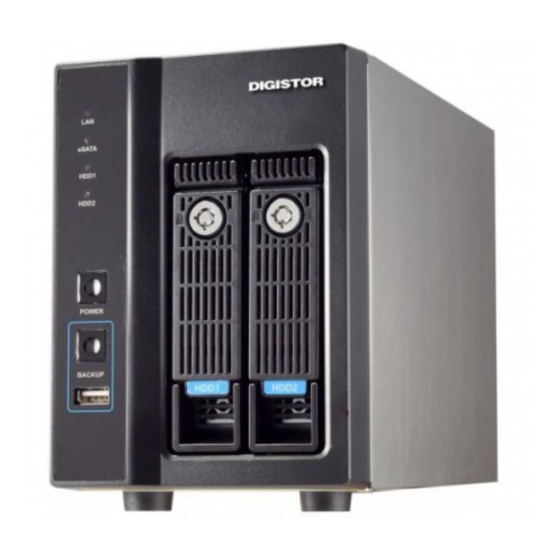
1.1 Hardware Description 1.1.1 DS-2000 Series DS-2005/DS-2009/DS-2012/DS-2016/DS-2020/DS-2025/DS-2032 Figure 1-1. Front & Rear View of DS-2000 Series Figure LED indicators: LAN, eSATA, HDD1, HDD2 Power button USB BACKUP button- Auto video backup USB 2.0 X1(Support auto video backup) HDD1 HDD2 Gigabit LAN USB 2.0 x 2... -
Page 8: Ds-4000 Series
1.1.2 DS-4000 Series DS-4005/DS-4009/DS-4012/DS-4016/DS-4020/ DS-4025/ DS-4032 Figure 1-2. Front & Rear View of DS-4000 Series LED indicators: LAN, eSATA, HDD1, HDD2, HDD3, HDD4 Power button USB BACKUP button- Auto video backup USB 2.0 x 1 (Support auto video backup) HDD1 HDD2 HDD3 HDD4... -
Page 9: Ds-1100 Pro Series
1.1.3 DS-1100 Pro Series DS-1105Pro/ DS-1109Pro/ DS-1112Pro/ DS-1116Pro/ DS-1120Pro/ DS-1125 Pro/ DS-1132 Pro/ DS-1136 Pro Figure 1-3. Front & Rear View of DS-1100 Pro Series Power button LED indicators: HDD USB 2.0 x1 (Support auto video backup) USB 2.0 x1 Power connector USB 3.0 x 2 DVI-I... -
Page 10: Ds-2100 Pro Series
1.1.4 DS-2100 Pro Series DS-2105Pro/ DS-2109Pro/ DS-2112Pro/ DS-2116Pro/ DS-2120Pro/ DS-2125 Pro/ DS-2132 Pro/ DS-2136 Pro Figure 1-4. Front & Rear View of DS-2100 Pro Series Power button LED indicators: HDD USB 2.0 x1 (Support auto video backup) USB 2.0 x1 Power connector USB 3.0 x 2 DVI-I... -
Page 11: Ds-4200 Pro Series
1.1.5 DS-4200 Pro Series DS-4205Pro/ DS-4209Pro/ DS-4212Pro/ DS-4216Pro/ DS-4220Pro/ DS-4225Pro/ DS-4232 Pro/ DS-4236 Pro Figure 1-5. Front & Rear View of DS-4200 Pro Series LED indicators: LAN1, LAN2, eSATA, HDD1, HDD2, HDD3, HDD4 Power button USB BACKUP button - Auto video backup USB 2.0 x 1(Support auto video backup) USB 2.0 x 1 HDD1... -
Page 12: Ds-4200-Rm Pro Series
1.1.6 DS-4200-RM Pro Series DS-4209-RMPro/ DS-4212-RM Pro/ DS-4216-RM Pro/ DS-4220-RM Pro/ DS-4225-RM Pro/ DS-4232-RM Pro/ DS-4236-RM Pro Figure 1-6. Front & Rear View of DS-4200-RM Pro Series 1. LED indicators: LAN1, LAN2, eSATA, HDD1, HDD2, HDD3, HDD4 2. Power button 3. -
Page 13: Ds-8200-Rm Pro Series
1.1.7 DS-8200-RM Pro Series DS-8209-RMPro/ DS-8212-RM Pro/ DS-8216-RM Pro/ DS-8220-RM Pro/ DS-8225-RM Pro/ DS-8232-RM Pro/ DS-8236-RM Pro Figure 1-7. Front & Rear View of DS-8200-RM Pro Series 1. LED indicators: LAN1, LAN2, eSATA, HDD1, HDD2, HDD3, HDD4, HDD5, HDD6, HDD7, HDD8 2. -
Page 14: Led Indicators Status
1.2 LED Indicators Status 1.2.1 DS-2000 Series DS-2005/ DS-2009/ DS-2012/ DS-2016/ DS-2020/ DS-2025/ DS-2032 Figure 2-1. DS-2000 Series Front Panel & RJ-45 Port LED on Front Panel LED Color & Status Indicate LAN Link is not established Orange LAN Link is established... - Page 15 LED on RJ-45 Porton Rear Panel LED Position LED Status Indicate LAN Link is not established Link/Activity Yellow LAN Link is established (Right LED) Yellow blinking LAN Activity is occurring 10M/100Mbps connection or no Speed connection (Left LED) Orange 1000Mbps connection Note: **USB BACKUP will beep and process after long pressing BACKUP button for 3 seconds.
-
Page 16: Ds-4000 Series
1.2.2 DS-4000 Series DS-4005/ DS-4009/ DS-4012/ DS-4016/ DS-4020/ DS-4025/ DS-4032 Figure 2-2. DS-4000 Series Front Panel & RJ-45 Port LED on Front Panel LED Color & Status Indicate LAN Link is not established Orange LAN Link is established Orange blinking LAN is being accessed No data transmission eSATA... -
Page 17: Ds-1100 Pro Series
LED on RJ-45 Port on Rear Panel LED Position LED Status Indicate LAN Link is not established Link/Activity Yellow LAN Link is established (Right LED) Yellow blinking LAN Activity is occurring 10M/100Mbps connection or no Speed connection (Left LED) Orange 1000Mbps connection *USB BACKUP will start and beep after 3 seconds user presses BACKUP button. -
Page 18: Ds-2100 Pro Series
1.2.4 DS-2100 Pro Series DS-2105 Pro/ DS-2109 Pro/ DS-2112 Pro/ DS-2116 Pro/ DS-2120 Pro/ DS-2125 Pro/ DS-2132 Pro/ DS-2136 Pro Figure 2-4. DS-2100 Series Front Panel Note: **To turn off your NVR, long pressing power button at least 2 seconds. **To turn on your NVR, long pressing power button at least 3 seconds. -
Page 19: Ds-4200 Pro Series
1.2.5 DS-4200 Pro Series DS-4205Pro/ DS-4209Pro/ DS-4212Pro/ DS-4216Pro/ DS-4220Pro/ DS-4225Pro/ DS-4232 Pro/ DS-4236 Pro Figure 2-5. DS-4200 Pro Series Front Panel & RJ-45 Port LED on Front Panel LED Color & Status Indicate LAN Link is not established Orange LAN Link is established Orange blinking LAN is being accessed No data transmission... - Page 20 LED on RJ-45 Connection at Rear Panel LED Position LED/State Indicate LAN Link is not established LAN1 Link/Activity Yellow LAN Link is established LAN2 (Right LED) Yellow Blinking LAN activity is occurring 10Mbps connection or no connection LAN1 Speed Green 100Mbps connection LAN2 (Left LED)
-
Page 21: Ds-4200-Rm Pro Series
1.2.6 DS-4200-RM Pro Series DS-4209-RM Pro/ DS-4212-RM Pro/ DS-4216-RM Pro/DS-4220-RM Pro/ DS-4225-RM Pro/ DS-4232-RM Pro/ DS-4236-RM Pro Figure 2-6. Front View of DS-4200-RM Pro Series & RJ-45 Port LED on Front Panel LED Color & Status Indicate LAN Link is not established Orange LAN Link is established Orange blinking... - Page 22 LED on RJ-45 Connection at Rear Panel LED Position LED/State Indicate LAN Link is not established LAN1 Link/Activity Yellow LAN Link is established LAN2 (Right LED) Yellow Blinking LAN activity is occurring 10Mbps connection or no connection LAN1 Speed Green 100Mbps connection LAN2 (Left LED)
-
Page 23: Ds-8200-Rm Pro Series
1.2.7 DS-8200-RM Pro Series DS-8209-RM Pro/ DS-8212-RM Pro/ DS-8216-RM Pro/DS-8220-RM Pro/ DS-8225-RM Pro/DS-8232-RM Pro/ DS-82326-RM Pro Figure 2-7. Front View of DS-8200-RM Pro Series & RJ-45 Port LED on Front Panel LED Color & Status Indicate LAN Link is not established Orange LAN Link is established Orange blinking... - Page 24 LED on RJ-45 Connection at Rear Panel LED Position LED/State Indicate LAN Link is not established LAN1 Link/Activity Yellow LAN Link is established LAN2 (Right LED) Yellow Blinking LAN activity is occurring 10Mbps connection or no connection LAN1 Speed Green 100Mbps connection LAN2 (Left LED)
-
Page 25: Dual-Monitor Solution: Hdmi/Vga/Dvi-I Connection
1.3 Dual-Monitor Solution: HDMI/VGA/DVI-I Connection DS-4200 Pro Series, DS-4200-RM Pro Series and DS-8200-RM Pro Series provide HDMI and VGA port for local display. Users can connect both of HDMI and VGA at the same time for video output. DS-1100 Pro Series and DS-2100 Pro Series provide HDMI and DVI-I port for local display. -
Page 26: Chapter 2. Nvr Installation
Chapter 2. NVR Installation 2.1 Remote PC System Requirements The following information is the minimum required specification for remote Windows PC, which users can open a remote browser from the PC to access the Linux NVR server on the network. Operating System ... -
Page 27: Connect To Nvr
2.2 Connect to NVR To begin, please insert the product CD-ROM in a PC to access the Quick Guide, User Manual and install the utilities. As user runs the product CD, the following menu is displayed. 2.2.1 Quick Guide Click “Quick Guide” to enter the folder and double click the file to open. - Page 28 When installing EZ Search, Shield Wizard window for EZ Search will pop up. Click “Next” to continue installation. Read the license agreement and click “I accept the terms of the license agreement”. Click “Next” to continue installation.
- Page 29 Select a location of destination and select a folder where the setup can install files. The default location is: C:\Program Files (x86)\DIGIEVER\EZ Search. Users can also install EZ Search in other folder by clicking “Change” and select a location as below.
- Page 30 The window shows that the InstallShield Wizard is installing EZ Search. Please wait until the Wizard completes the installation. The InstallShield has successfully installed EZ Search. Select “Create Desktop Shortcut”/ “Create Quick Launch Shortcut”/ “Create Start Menu Shortcut” and please click “Next” to continue.
- Page 31 The installation is complete. Please click “Launch application when done installing” to execute EZ Search. After finishing the setup, the window of EZ Search will pop up. Easy Search will execute automatically and show NO., Name, IP Address, Mac Address and Model name of connected NVR. Users can click “Search”...
- Page 32 Introduction of EZ Search EZ Search provides three kinds of toolbars for users: File You can click “Exit” to leave EZ Search and close the window. 2. Setting Configure UPnP and Network by clicking “Setting” in the top left or in the middle right.
- Page 33 When accessing the NVR setting, users will be prompted to enter username and password. For the first-time use, the default username and password are admin/admin. When the correct username and password have been entered, click “Login” to continue. 1) UPnP Universal Plug and Play (UPnP) simplifies the process of adding a NVR to a local area network.
- Page 34 2) Network Two models are provided for setting the network: DHCP and Static IP.
- Page 35 3. Option Option provides several languages Once you click “Connect” or double click the selected NVR list, IE browser will pop up automatically for the web-based interface.
-
Page 36: Install S-Nvr Decoder
2.2.3 Install S-NVR Decoder Click “Install S-NVR Decoder” to install decoder and follow the instructions to setup. Install Shield Wizard window will pop up and please click “Next” to continue installation. Read license agreement and click “I accept the terms of the license agreement.” Click “Next”... -
Page 37: User Manual
The installation Wizard is installing S-NVR Decoder. The installation is complete. Please click “Finish” to close the window. 2.2.4 User Manual Click “User Manual” to open the folder and double-click on user manual file to read. 2.2.5 Browse CD Click “Browse CD” to open the folder of current Autorun.exe file. - Page 38 2.2.6 Activate Live View Service 1. Connect to NVR After setting the EZ Search and S-NVR Decoder, users can connect to the web-based interface by the following two options: EZ Search or IE browser 1) EZ Search Once you click “Connect” or double click the selected NVR list, the IE browser will pop up automatically.
- Page 39 4. Allow ActiveX Control After logging in the NVR, users are recommended to install ActiveX control for the first-time installation. 1) Left-click on the description “This website wants to run the following add-on: ‘NVR ActiveX’ from…..” 2) Left-click on the description “Run Add on.”...
- Page 40 3) Left-click “Run” to use licensed ActiveX controls.
-
Page 41: Quick Configuration
2.3 Quick Configuration After users log in NVR and install the ActiveX control, the system will direct you to set Quick Configuration in five main steps. Follow the instructions of the Overview of wizard to complete system setup. 2.3.1 Start System will lead you to “Start”... -
Page 42: Network Settings
2.3.2 Network Settings Please select “Network Settings” from the drop-down menu of Configuration Utility to begin. Users need to adjust the settings in the Network Setup page in order to let NVR work properly within network. There are 2 methods to configure IP address ... -
Page 43: Server Settings
To assign a static IP address to the NVR: 1. Select “Specify an IP address” 2. Enter the IP address, Subnet Mask, Default Gateway IP Address and DNS server address. 3. If IP Address is changed, user needs to log out NVR and login in again. Click “Next”... -
Page 44: Date &Time
Server name with UPnP Universal Plug and Play (UPnP) simplifies the process of adding a NVR to a local area network. Once connected to LAN, the NVR will automatically appear on the internet. User can select to enable the function with UPnP and edit a sever name. Password Settings ... - Page 45 Time Zone: Synchronize with an Internet time server automatically. Select the time zone of your area and update the date and time of the NVR automatically with an NTP server. User also has an option to automatically adjust daylight saving time. Configure the time and date by verifying and adjusting current local time and daylight saving to avoid the following errors: Incorrect display time for playback videos.
-
Page 46: Disk Management
2.3.5 Disk Management Please select “Disk Management” from the drop-down menu of Configuration Utility to begin. If hard disk is not installed in NVR, the page will show “Disk doesn’t exist.” Once an available hard disk drive is inserted into the tray, Disk Information will show in Device Information and users can start to create new RAID Disk. - Page 47 Create As the hard disk drive is available, the status of Device Information shows “Ready,” which indicates the hard disk drive is ready to be created. Please click “Create” to enter the window for building New RAID Disk and select the hard disk drive in the Free HDDs field.
- Page 48 The selected hard disk drive in the Free HDDs field will be marked in blue and please click to recruit the hard disk drive into Assigned HDDs field. The selected hard disk drive in Assigned HDDs field will be marked in blue. Meanwhile, Target RAID Disk is ready to build RAID disk and it shows five types of disk configuration.
- Page 49 Fault A minimum of 3 hard disk drives are required to create RAID5. The Tolerant data are striped in all hard drives in a RAID5 array and the parity (Raid5) information is stored in each drive. If a hard disk drive fails, the array enters degraded mode.
- Page 50 The progress is under “formatting….20%”. Please wait till 100%. The progress is in “Create swap” and is going to finish the disk building. Finally, the RAID disk building is complete. After the RAID disk is created, RAID List shows RAID Name and available storage devices.
- Page 51 Delete After the RAID Disk is created, “Delete” option is available. If user is going to delete RAID disk, please refer to following description. In “Delete” option, user can remove or format RAID disk by selecting the RAID disk. In the table, RAID Name, RAID type, Capacity and Status are shown. Remove ...
- Page 52 If users want to change the RAID level setting, please click ‘‘Remove.’’ After the RAID Disk is removed, the Status in Device information shows “Ready,” then users can go back to Create page to continue the new RAID level configuration. Note: Once you remove the disk and continually create it, the recorded video will be formatted.
-
Page 53: Camera Settings
Hard disk drive is formatting. Please wait for formatting until 100%. 2.3.6 Camera Settings NVR provides two options to add new cameras: UPnP Search and Detect Detect: In this option, users are asked to enter IP Address and vendor. Then, click “Apply” to start adding camera. - Page 54 Camera Name, Username and Password are editable. After selecting a specific camera vender, username and password will be automatically filled in by vendor’s default information. Memorize modified username and password: NVR also can memorize username and password which is modified by users after users click “Apply”...
- Page 55 adopt camera setting by selecting “Setting from Camera.” This option can largely save users’ time and effort when users install surveillance systems. Note: It is highly recommend to use “Optimization by NVR” to perform the best surveillance quality in both live-view and playback. If there is any error occurred in entering the following information, the notification window will pop up as below.
- Page 56 All applied cameras will be shown in Camera List and if no more camera needs to be connected, please click “Next” to continue configuration. Delete If any camera should be deleted from camera list, please click the column turning into blue and click “Delete.”...
- Page 57 The camera has been deleted from camera list. Generic RTSP/ Generic MJPEG NVR provides the interface for users to enter RTSP/ MJPEG URLs of IP cameras to receive the video streaming from IP camera. The streaming will be applied to monitoring, recording and playback.
- Page 58 The most correct URLs should be provided from each camera vendors. Users may also refer to websites https://www.soleratec.com/rtsp/ http://www.ispyconnect.com/sources.aspx UPnP Search: Click “UPnPSearch” to find out UPnP devices within the LAN. Please make sure IP camera supports UPnP Search function. Please go to IP Camera web page to enable UPnP search function.
- Page 59 The available cameras in the network will be displayed. Add any camera you want by clicking “Add” from the list one by one. After the search, the window displays Camera Name, IP Address, User Name, Password, Port, Vendor and Model. Please click “Apply” to add new camera. Note: NVR will automatically fill in default username and password of each vendor.
- Page 60 You can also click “Delete” to disconnect the camera.
-
Page 61: Finish
2.3.7 Finish Please select “Finish” from the drop-down menu of Configuration Utility to begin. Once five steps of Quick Configuration are completed, the window will show the completed status. You can click “Back” to return to the previous steps to modify the configuration or click “Start Live view”... -
Page 62: Chapter 3. Use Nvr By Local Display
Chapter 3. Use NVR by Local Display NVR can be connected to a monitor via HDMI and VGA port to execute quick configuration and display live view. Note: Local display feature is supported in DS-1100 Pro, DS-2100 Pro, DS-4200 Pro Series, DS-4200-RM Pro Series and DS-8200-RM Pro Series. To start local display, please check the steps below: 1. -
Page 63: Anonymous Login
3.1.1 Anonymous login Anonymous login allows users to login without username and password. Anonymous user can only view live monitoring and playback page in local monitor, however, the configuration page will be disable. While anonymous login is applied, system will automatically log in without authorization process after boot up. Start to setup the anonymous login A. -
Page 64: Virtual Keyboard
3.1.2 Virtual Keyboard Users can choose to use USB keyboard for typing in local display of NVR, or fill out columns with virtual keyboard. The virtual keyboard in local display can be enabled from the right side of each column. There are 3 types of virtual keyboard can be chosen, including Upper case, Lower case and Symbols. -
Page 65: Quick Configuration
3.2 Quick Configuration After you log in local display of NVR, the system will direct you to set Quick Configuration in five main steps. Follow the instructions of the Overview of wizard to complete the system setup. Please refer to chapter 2.3 Quick Configuration for more information. 3.3 Live View After the Quick Configuration is complete, users can successfully monitor IP cameras. -
Page 66: Main Functions For Live View
On top right of live view, users can select four view modes. Mode Description Live View: Click “Live View” to control the monitoring instantaneously. Playback: Click “Playback”to play and to export the recorded video files. Configuration: Click “Configuration”to configure camera, recording, event, management, network, quick configuration and system. - Page 67 Event: When event happens, NVR shows warning to user for instant alert. Recording status: The window shows whether camera is recording or not. Blue border: The outline border surrounds the selected window to highlight the focus image. NVR information (1) Firmware version User can easily find out the firmware version in the live view page.
- Page 68 Drop: Drop the camera from monitoring. Drop all: Drop all cameras from monitoring. Add all: Add all cameras from monitoring. Mute: Alter sound instrument from camera. Date & Time: Showthe specific day and time. Display mode NVR supports multi-display modes for monitoring. Click the icon of display mode to monitor live view.
- Page 69 Click to choose the page of liveview PTZ Control Panel If the IP camera supports PTZ function, user can use the control panel to adjust the viewing angle. The following functions are available depending on the camera models. Icon Description PTZ panel: PTZ allows users to monitor large areas with a single network camera.
- Page 70 Event Log Event log is a convenient feature to notify users of motion detection at the very first time. When a motion is detected, the icon will start blinking. By clicking the button, a window will pop up to display the list of event log as below. Users can view all detailed list of motion detection in both local display and remote web browser.
- Page 71 Highlight video window when event is triggered The option of “Highlight video window when event is triggered” is a warning frame which will pop out on the channel when an event is detected. When the motion event is awarded, user can simply click on the channel with mouse, the warning frame will be stopped.
-
Page 72: Right Click Functions On Video Window
automatically close after users assigned seconds. (Default is 10 seconds) 2) Sequential mode setting Click sequential interval to set the numbers of user-defined seconds for sequential mode. 3.3.3 Right Click Functions on Video Window 1. Video Size: Original or Fit... - Page 73 2. Streaming change: NVR allows users to setup the dual streaming configurations in camera parameter page if cameras support dual stream. It is suggested stream 1 is set for higher resolution and stream 2 for lower resolution, which helps users to choose the proper streaming in live view with intuitive control.
-
Page 74: Zooming With Mouse Scroll
3.3.4 Zooming with Mouse Scroll In addition to digital zoom in/out button, users can use mouse scroll to prevent potential crisis in live-view monitoring. Note: For PTZ cameras, zooming with mouse in live-view is adopted optical zoom in/out. If users would like to view more detailed image, please use zooming with mouse scroll first and then click digital zoom in/out button. -
Page 75: Playback
Playback Playback is a function that allows users to view recorded videos from cameras connected to NVR. NVR offers synchronized playback up to four cameras and easy steps provided to help user sort through the recorded videos quickly. 3.4.1 Steps to Playback Videos Users can easily search recorded videos by following playback steps. - Page 76 1. Select cameras from camera list Users can select up to four cameras to play the recorded video. 2. Select date and time Users can designate the specific date and time to playback video. If the selected cameras have recorded videos, the date will be shown in a blue background in default (Normal Record).
- Page 77 Frame by Frame Playback 1 Follow above four steps of Playback 2 Click “Pause” 3 Click “Previous image” or “Next image”...
-
Page 78: Main Functions For Playback
3.4.2 Main Functions for Playback 1. Display mode The screen shows the recording time of each channel in the top of each grid. Click to view the video in full screen. One-screen and four-screens are also provided to display playback. 2. - Page 79 4. Video playback speed control (1) Pause: to temporarily stop the playback. (2) Previous Image: to show the earlier image. (3) Speed down: to play in slower speeds. (4) Play: to play video file. (5) Speed up: When you click “speed up,” the recorded video will play faster. (6) Next image: to show the next image (7) Rewind: to let video automatically wind backward Playback speed status is beside scroll bar.
-
Page 80: Export Files
3.4.3 Export Files Export function allows users to export file to USB device or USB type DVD burner directly. Please select cameras, video file types, date and the time period first, and then click the export button to copy the files. Users will be asked whether DIGIPlayer and DIGICheck should be downloaded with video files. -
Page 81: Zooming With Mouse Scroll
plug in USB device for the export of snapshot images and it will have 10 sequential images to be saved in the USB dongle. 3.4.5 Zooming with Mouse Scroll In addition to digital zoom in/out button, users can use mouse scroll to find out crucial proof in incident site in playback Please click on the video window and use mouse scroll to zoom in or zoom out Others... -
Page 82: Usb Backup By Software Usb Backup Virtual Button
Note: System upgrade in local display is supported in DS-8200-RM Pro Series, DS-4200-RM Pro Series, DS-4200 Pro Series, DS-2100 Pro Series and DS-1100 Pro series. 3.5.3 USB Backup by Software USB BACKUP Virtual Button Users can easily back up recorded video by clicking “USB Backup” button in local display user interface. -
Page 83: Chapter 4. Use Nvr By Remote Web Browser
(4) Click “USB backup” button to back up Chapter 4. Use NVR by Remote Web Browser Users can adopt multiple web browsers ( IE/ Chrome/ Firefox/ Opera browser in Windows) to monitor the network camera and view playback. Live View After the Quick Configuration is complete, NVR will guide you to live view. -
Page 84: Select View Modes On Live View Page
4.1.1 Select View Modes on Live View Page On top right of live view, users can select four view modes. Mode Description Live View: Click “LiveView” to control the monitoring instantaneously. Playback: Click “Playback” to play and to export the recorded video files. Configuration: Click “Configuration”... -
Page 85: Main Functions For Live View
4.1.2 Main Functions for Live View 1. Camera status Icon Description Camera name: The name of the camera is located in the top left corner in each video window. Users can rename the camera via the path “Configuration->IP Camera->Camera Settings.” Video compression format: M-JPEG/MPEG-4/H.264 Audio: Once camera supports audio, NVR shows audio in blue. - Page 86 (2) Current time Users can find out current time directly. (3) Disk and CPU loading indicator: Users can find out Disk and CPU loading directly without entering configuration page. Disk and CPU indicator shows blue when loading is70% or under, and shows red as a warning when it reach to more than 70%.
- Page 87 editing. 2) Save: To save image to default path. 3) Cancel: To cancel snapshot. Digital zoom in/ out: Select a channel to enable digital zoom function Drop: Drop the camera from monitoring. Drop all: Drop all cameras from monitoring. Add all: Add all cameras from monitoring.
- Page 88 5. Display mode NVR supports multi-display modes for monitoring. Click the icon of display mode to monitor live view. When you click a display mode, the mode icons will turn into blue. Icon Description Full Screen 1 screen 4 screen 9 screen 10 screen 12 screen...
- Page 89 6. PTZ Control Panel If IP camera supports PTZ function, users can use the control panel to adjust the viewing angle. The following functions are available depending on the camera models. Icon Description PTZ panel: PTZ allows users to monitor large areas with a single network camera.
- Page 90 At the same time, the icon will stop blinking. Enable Alert sound If users enable the function, the remote web browser will sound the alarm to notify users when motion detection is triggered. (Alert sound can also be set in Option>General.) 8.
- Page 91 Automatically reorder Liveview windows To rearrange video in order without blank grid after users drop video from live-view. Resize all video sizes at the same time Only a right click on the video, users can set "all" video size either in original size or fit size.
- Page 92 Liveview event notification with video pop-out window Once the feature is enabled, a new window will pop out when an event is triggered so as to inform users of event happened at the very first time. By clicking button at the top-right corner, users can manually close the pop-out window.
- Page 93 2) Multi-Server: Users can save the camera list of multi-server in live-view page. 3) Sequential Mode Setting: Click sequential interval to set the numbers of user-defined seconds for sequential mode. 4) Joystick Users are able to manipulate PTZ camera with USB joystick. Choose the joystick column and select joystick model then press ‘‘Apply’’...
- Page 94 Joystick can work on PTZ cameras as the status bar is with PTZ icon. Note: NVR supports joystick in remote web client.
-
Page 95: Right Click Functions On Video Window
4.1.3 Right Click Functions on Video Window 1. Mute: To mute the audio of the video 2. Video Size: Original or Fit 3. Streaming change: To exchange the streaming resource. (1) Exchange Streaming NVR allows users to setup the dual streaming configurations in cameras parameters page if cameras support dual stream. - Page 96 (2) Stream from Server In case that NVR performance is violated by camera limitation, stream from server is an optional choice for users to view video images. It is highly recommend to use “Enable Optimization” to perform real-time monitoring Note: Enable stream 1 from server may influence the efficiency of NVR. 4.
-
Page 97: Zooming With Mouse Scroll
(2) Dewarp for Immervision Lenses a. Choose dewarp type: b. Chosse display mode: 4.1.4 Zooming with Mouse scroll In addition to digital zoom in/out button, users can use mouse scroll to prevent potential crisis in live-view monitoring. Note: For PTZ cameras, zooming with mouse in live-view is adopted optical zoom in/out. -
Page 98: Multi-Nvr Server
4.1.5 Multi-NVR server Users can add multi-NVR server by clicking “Searching NVR.” Please insert account and password of the NVR which you are going to add to the local server, and then the NVR which is located in LAN will appear, including the local NVR. -
Page 100: Playback
4.2 Playback Playback is a function that allows users to view recorded videos from cameras connected to NVR. NVR offers synchronized playback up to four cameras and easy steps to help users sort through the recorded videos quickly. Playback video can be viewed in full screen;... - Page 101 Please follow four steps below to quickly search recorded videos: 1. Select cameras from camera list 2. Select date and time period 3. Select recording type 4. Click “Play” 1. Select cameras from camera list Please select channel number from channel list to search recorded videos. Up to 4 channels can be selected at the same time.
- Page 102 If there is an event recording in the specific date, the date will be remarked as blue with red stripe aside. Users can also select specific time period from time searching list (start time to end time.) Start time and end time layout is Hour: Minute: Second. The default time period is from 00:00:00 to 23:59:59.
- Page 103 Frame by Frame Playback 1 Follow above four steps of Playback 2 Click “Pause” button 3 Click “Previous image” or “Next image” button Scale bar Users can move thebarto enlarge or narrow downthe time period to check video files from Time table.
- Page 104 From the thumbnail, users can also read the related information such as date, time and camera name. The thumbnail will be shown while pointer moves on the footage.
-
Page 105: Main Functions For Playback
4.2.2 Main Functions for Playback Display mode NVR supports multi-display modes for playback. When you click a display mode, the mode icons will turn into blue. Icon Description Full Screen 1 screen 4 screen 9 screen 16 screen Video playback speed control (1 ) (2) (5) (6) (1) Pause: to temporarily stop the playback. - Page 106 (3) Slow motion: to play in slower speeds. (4) Play: to play video file. (5) Speed up: When you click “speed up,” the recorded video will play faster. (6) Next image:to show the next image (7) Rewind: to let video automatically wind backward The play speed status is beside display mode.
- Page 107 Dewarp for fisheye cameras By right click on the video, users can choose the proper dewarp engine for fisheye camera. a. Choose the dewarp engine: b. Choose the mounting type c. Choose the display mode...
- Page 108 Change OSD color and font size Users can select different OSD color while having the playback of recording files. 1) Click “Setting” 2) Click OSD “color” setting button the select the OSD color and click “OK” 3) Select font size and click “OK”...
- Page 109 4) All OSD color will shown as the selection Default button By clicking “Default” button, users can default OSD setting. Default font size is 20 in orange color.
-
Page 110: Export Files
4.2.3 Export Files Export function allows users to retrieve recorded files from the server. Before exporting file, users are recommended to set AVI path from “Setting” button. 1. Select the Storage AVI Path Playback setting page indicate the path where exported files, DIGIPlayer and DIGICheck to be saved. -
Page 111: Play Video Files
4. To cancel the transfer. Users can cancel the files transferred while downloading files from NVR. 4.3 Play Video Files Users can access the video files by Windows Networking and FTP Service. Note: To use Windows Networking and FTP Service, please enable both in“File Sharing Service”... - Page 112 Note: The default device name of each connected NVR is from “Mac Address” of each NVR, which can be found in configuration page. To acquire Mac address, users can refer to “System” > “Device Information” >“System Information” in configuration page. “Computer Name”...
- Page 113 As you select the NVR, a window will pop up and ask to enternetwork password. If users don’t amend the user name and password, please enter the default ones:“admin/admin.” After users enter accurate user name and password, the NVR will display the folder “Public”...
- Page 114 After entering “videodata1,” the folder displays RecordFolderchronologicallyby recording dates. Please select a folder to enter. All video files lists chronologically by recorded time and video length of each chunk is five minutes. Select a video file to play. Enter IP Address to Search ...
- Page 115 As you enter the IP address, a window will pop up and ask for network password. If users don’t amend the user name and password, please enter the default ones:“admin/admin.” After users enter accurate user name and password, the folder of NVR displays the folder “videodata1.”...
-
Page 116: Ftp Service
4.3.2 FTP Service To access FTP service in a web-based interface, please open Windows Internet Explorer and enter NVR IP address which users configure. As you enter the IP address, a window will pop up and ask to typea user name and password to log in FTP server. - Page 117 Please click “Log On” to proceed. IE browser shows the folders on FTP server. Please select folder “videodata1”.
- Page 118 The folder displays RecordFolder chronologically by recording dates. Please select a folder to enter. All video files lists chronologically by recorded time and video length of each chunk is five minutes. Select a video file to play.
-
Page 119: Chapter 5. Configuration
Chapter 5. Configuration In configuration page, users can configure Quick Configuration, IP Camera, Recording & Event, Disk Management, NetworkManagement and System from each drop-down menu. Note: NVR will automatically log out from configuration page after idle for 10 minutes. IP Camera 5.1.1 Camera Settings Please refer to Chapter2 - 2.3.6 Camera Settings. - Page 120 NVR supports multi-stream for monitoring and recording. Users can modify camera’s configuration such as video format, frame rate, resolution, video quality, audio enable and stream target via NVR in this page. There are two parts in this section: Parameter and Camera List. Please select a camera in Camera List first.
- Page 121 by the network surroundings. Resolution Select resolution from drop-down listfor your camera. Video Quality Select either “VBR”(Variable bit rate) or “CBR” (Constant bitrate) to set the video quality. Audio Enable To make audio recording function enable or disable. Stream Target ...
-
Page 122: Camera Status
5.1.3 Camera Status Please select “Camera Status” from the drop-down menu of IP Camera to begin. Camera List shows connection status of recording. -
Page 123: Recording & Events
Recording & Events Recording & Events can provide different event modes and recording schedule for users to configure IP camera. Event & Action Management also allows users to combine various events and its triggered actions to achieve the security surveillance. If the hard disk is not installed, the following window will pop up when you click “Recording &... - Page 124 No Recording: Once “No Recording” is selected, all cameras will be disabled to record the video. Event Recording: Once “Recording by Schedule” is selected, Recording by Schedule: Once “Recording by Schedule” is selected, users can set the scheduled time to record the video. Users should configure the schedule in “Recording Schedule”...
-
Page 125: Recording Schedule
5.2.2 Recording Schedule Users can configure Recording Schedule to define time range for all channels. Insert schedule Select time range and channel for recording schedule and click “Insert.”... - Page 126 After inserting time range and channel, the time/camera bar displays the selected time. Click “Apply” to finish setting or “Reset” to rearrange time and camera channel. Note: A camera can set multi-recording schedule at same time as below picture. Delete schedule Users can erase the specific time in recording schedule by selecting the time then click"Delete".
-
Page 128: Event & Action Management
5.2.3 Event & Action Management Please select “Event & Action Management” from the drop-down menu of Recording & Event to begin. “Event & Action Management” allows users to define alarm setting that manage events and its corresponding action. When an event occurs, NVR will perform certain actions. - Page 129 5. NVR event: Recording Error 6. NVR event: Digital Input 7. External event(HTTP-in) An event type is a set of parameters that defines different actions. Check an event type and click “Add” to select NVR Action. Note: The action will be only triggered when the action is added to the event. 1.
- Page 130 If “Attached with the snapshot” is enabled, the Email will be sent with snapshot of the event. Click “Apply” to finish the configuration. E-Mail action will be triggered once per 20 seconds as the event is happening, which means if an event is lasting for one minutes, NVR will send email 3 times per every 20 seconds.
- Page 131 User Defined Action User Defined Action allows users to send the specific HTTP command out when an event is triggered in order to manage devices such as power controller, fire/smoke protection device, etc.
- Page 132 SMS stands for Short Message Service. Users can be notified by short message service while the event is triggered. The service is supported by Clickatell users need to register for the service. It supports only for English message currently. Settings: 1.
- Page 133 Event Triggered Record You can enable Event trigger record and Video Clip. Event triggered record: When event is triggered, NVR records video and records every five minutes as the event continues happening. Video Clip: Video clip will be sent by E-mail and you can change the Pre-time and Post-time through “Advanced Settings.”...
- Page 134 4. NVR event : Disconnected You can set action as “Digital Output.” Once NVR loses its network connection, the actions can be triggered. 5. NVR event : Recording Error You can set action as “Send E-Mail” and “SMS.” Once NVR fails in recording, the actions can be triggered.
- Page 135 6. NVR event: Digital Input You can set action as “Event Trigger Record,” “Send E-Mail” and “Digital Output”, “User Defined Action” and “SMS.” Once Digital Input is detected from camera, multiple actions can be triggered. 7. External event(HTTP-in) You can set action as “Event Trigger Record,” “Send E-Mail” and “Digital Output”, “User Defined Action”...
-
Page 136: Advanced Setting
Event could be triggered by external HTTP-in CGI command. It allows users to define up to 5 different HTTP-in events. With the “External Event”, users can set its actions just like other events. The format of external HTTP-in event CGI : http://<NVR_IP>/login.cgi/cgi_main.cgi?cgiName=event_ipc.cgi&eventName=Defined_ <int>... -
Page 137: Event Schedule
Pre-time of record can up to 300 seconds before the event is triggered and Post-time of record can up to 300 seconds after the event ends. Event Triggered with Audio Users can set up whether Audio is recorded only when an event is triggered. When “Event Triggered with Audio”... - Page 138 C. Setup event schedule. Select the type of event Schedule By Day 1. Select the camera 2. Designate the time period 3. Click Insert button to be effective 4. Designated duration will be displayed 5. Designated duration is shown on chart Press “Apply”...
- Page 139 By Week 1. Select the schedule as “Week” 2. Select the day for the specific recording schedule 3. Designate the time period 4. Select the camera for adaption 5. Click insert to be effective 6. The designated duration will be displayed 7.
- Page 140 1. Designate the time period on chart by clicking on it 2. Click the Delete button 3. The designate period is removed Remove all alarm periods in one camera 1. Click any period of the camera 2. Select Delete All checkbox 3.
-
Page 141: E-Mail
5.2.6 E-Mail Please select “E-Mail” from the drop-down menu of Recording & Event to begin. SMTP Server Server Address: Enter the Server Address of the SMTP server. Sender: Specify sender’s E-Mail in the “Sender” field. Subject: Enter the Subject. ... -
Page 142: Disk Management
Contact List will show the information you entered. Please click “Apply” to finish settings. Result will show in the following Contactors List and users can delete the contactor or continue to add a new contactor. 5.2 Disk Management NVR can create new RAID disk or delete/format the RAID disk. Also, users can manage NVR’s storage device for data transmission and file sharing service. -
Page 143: File System Management
The steps for creating and deleting hard disk, please refer to the disk management of Quick Configuration. Please select “Disk Management” from the drop-down menu of Quick configuration to begin. 5.3.2 File System Management Please select “File system Management” from the drop-down menu of Disk Management to begin. - Page 144 File system provides an efficient method to organize data expected to be retained after a program is terminated by providing procedures to store, retrieve and update data, as well as manage the available space on the device.
-
Page 145: File Sharing Service
5.3.3 File Sharing Service Please select “File Sharing Service” from the drop-down menu of Disk Management to begin. Arrange data transmission service including Windows Networking and FTP service. When there is no hard disk installed in the NVR, the screen will show “No Filesystem.”... - Page 146 Windows Networking In Windows Networking field, users can enable or disable the services and Computer Name is already shown. Computer Description and Domain or Workgroup Name can be changed. FTP Service In FTP Settings, users can enable or disable FTP Services. User can arrange Command Port and Passive Port and configure language interface in Client Coding Type.
-
Page 147: Cloud
5.3 Cloud NVR provides cloud backup to upload recorded files to Dropbox. With cloud backup, users can share recorded files with a link. Please select “Dropbox” from the drop-down menu of Cloud to begin. 5.4.1 Setup Dropbox Service Please click “Apply” to start Dropbox webpage connection and to establish a folder in Dropbox. -
Page 148: Share Files To Dropbox Server
After successfully connecting with NVR, Dropbox will automatically create a file named “Dropbox”. Quit Setup When NVR is accessing to Dropbox, the NVR will display as below: If users want to cancel the Dropbox setting, please click “Apply” to remove setup. -
Page 149: Remove Configuration And Online Sync
5.4.3 Remove Configuration and Online Sync Please press“F5 button” on the keyboard to refresh the webpage. You can see the webpage as below: Remove Configuration and Data Please Click “Apply” to remove Dropbox service from NVR. All configuration and data of Dropbox in NVR will be deleted. -
Page 150: Network Setup
A warning will pop up when the folder cannot open. Please enter the same Lan domain as NVR. 5.4 Network Setup 5.5.1 Network Setup Please select “Network Setup” from the drop-down menu of Network to begin. This section explains how to configure network connection with NVR. Information Network information displays present network configuration including: Computer Name, IP address, Subnet mask, Default Gateway, Primary and Secondary DNS. - Page 151 Setup NVR supports dual IP application to connect different network segments to maximize network efficiency. Dual IP application allows users to efficiently communicate between internet and surveillance system. Dual IP application largely increased the resistibility of unauthorized data theft and the unavailability of accessing to cameras.
- Page 152 there is more than one NVR in the network. Separated IP Please enter two IP address to in LAN1 and LAN2 to set up different network environments. Please click “Apply” to execute the settings. DHCP Setup Built-in DHCP server allows users to easily install IP surveillance systems without connecting another router providing network parameters.
-
Page 153: Network Service
Port Setup Please set up transmission port to access NVR. Default port for NVR connection is 80. 5.5.2 Network Service Please select “Network Service” from the drop-down menu of Network to begin. Black/ White List Edit White or Black List to allow or block different IP address. - Page 154 As White List is enabled, a window will pop up to make sure the execution. As Black List is enabled, a window will pop up to make sure the execution. Please enter the IP address range to add to White List or Black List. Note: The above IP address is only an example for reference.
-
Page 155: Ddns
UPnP Enable or disable UPnP search. Rename UPnP. Note:The maximum character limitation for UPnP Name is32 characters. Please click “Apply” to execute the settings. 5.5.3 DDNS Please select “DDNS” from the drop-down menu of Network to begin. DDNS links a domain name to an IP address, allowing users to easily access their camera even with a changing IP address. -
Page 156: Management
5.5 Management In Management, users can easily create, modify and change users' live view access and playback access. Also, users can read various log information through log system and quickly save or load configuration of NVR. Emergent backup of the latest video files as well as the external input and output control can also be set here. - Page 157 Click “Apply” to add new Power User.
- Page 158 After the Power User is created, user list will display the information as below. User Administrator can select a group from “Group” drop-down list to assign a new User. Please enter a username and password in “User List.” And select Live View Access and Playback Access for the new User.
- Page 159 Modify User Please go to Modify User page. Select an account to modify the Power User or User. The selected account will turn to blue and the page for modifying user will appear as below. You can change Live View Access and Playback Access. Please click “Apply” to proceed.
-
Page 160: Log System
Change Password Each NVR comes with a built-in “admin” account with password “admin” for administrators. It’s highly recommended to change the password upon the initial login. Select an account from “User Name” drop-down list to change password. Enter a new password in the “New Password” and enter it again in “Retype Password.” Click “Apply,”... - Page 161 Hardware Log The log information in Hardware Log includes RAID creation, RAID deletion, RAID modification, CPU, buzzer, fan, system, sensor and USB. NVR Log The log information in NVR Log includes time zone, daylight, system, firmware upgrading, configuration IP, recording files export and storage.
- Page 162 Event Log The log information in Event Log includes “Camera is connected,” “The camera is disconnected,” “Digital Input,” “Motion detected” and “Storage usage is out of limit,” etc. Current User The log information in Current User shows the current users logged in the NVR with IP address.
- Page 163 File Access Log The message occurred is related to other method to get in NVR such as SAMBA or FTP. Export the log files Users can export and save log files from Log System page. And each log types correspond to one log file.
-
Page 164: Save/Load Configuration
5.6.3 Save/Load Configuration Please select “Save/Load Configuration” from the drop-down menu of Management to begin. If the raid disk is not built, the following window will pop up. Save Configuration Select Volume and Folder to save configuration in a format of cfg file and specify the File Name. - Page 165 Load Configuration Load configuration can help users duplicate the same settings from one NVR to another without configuring system manually. Users can select Load Type as “Load Default Settings” or “Load Configuration.” Once you select “Load Default Settings” and click “Apply,” configuration of Camera Setting, Recording Settings, Event &...
-
Page 166: Usb Backup
5.6.4 USB Backup Users can preset the latest duration and channels of USB Backup button on Remote Web Browser for quick backup the latest video files locally in the future. With USB Backup button setting, when users inserts USB device or USB type DVD burner into the USB port in the NVR (front panel backup area) and press “USB BACKUP”... - Page 167 USB Backup Button Setting in Remote Web Browsers Enable: USB Backup button function can be enabled or disabled, for security concern. The latest duration of recordings: Users can set a maximum of days and hours to backup the latest video files. ...
- Page 168 Device Information status When a USB device is inserted to the NVR, the USB Backup Device Information in Remote Browser will show the status “Wait..” When the USB is ready to begin, the Device Information will show the status “Ready,” and the USB LED indicator will show blue.
- Page 169 If there is no USB inserted into NVR, the screen will show “There is no USB device…” as below picture: Note: DIGIPlayer and DIGICheck will be downloaded with video files. DVD Backup USB Backup Button Setting in Remote Web Browsers ...
- Page 170 Software DVD Backup Virtual Button By clicking “USB Backup” button, NVR will save the settings (The latest duration of recordings and Channel selection) and export videos to USB device now. Please insert a USB device to start to backup the latest video files. Device Information status When a USB type DVD burner is inserted to NVR, Device Information of DVD Backup in Remote Browser will show the status “Wait...
- Page 171 Advance Settings Encryption of Exported Files Users can encrypt exported files to USB or DVD device as ZIP files in remote playback. Users need to decide password when exporting files in remote playback. Note: Encryption of Exported Files is supported in DS-4200 Pro Series, DS-4200-RM Pro Series and DS-8200-RM Pro Series.
-
Page 172: External Io Device
In local NVR, a window will pop up to ask users to enter password for encryption before exporting files. 5.6.5 External IO Device Please select “External IO Device” from the drop-down menu of Management to begin. Enter necessary information to add devices manually, including: Device Name, IP Address, User Name and Password. -
Page 173: Ups Management
automatically, if detectable. Camera List shows all available device information including: Camera Name, IP Address, Port, Vender and Model. Also, Device Event will show the event originally set in the device. 5.6.6 UPS Management Please select “UPS Management” from the drop-down menu of Management to begin. - Page 174 progress regular monitoring. UPS Management Settings–Smart Shutdown and Backup Smart Shutdown and Startup feature can maintain usual surveillance performance when users encounter power outage. Please enable UPS Support. Then, fill in numbers to automatically shutdown or startup NVR With Smart Shutdown and Startup, users can set up when to automatically shut down NVR (Sleep Mode).
-
Page 175: System
5.6 System 5.7.1 Device Information Please select “Device Information” from the drop-down menu of System to begin. System Information System Information shows Operating System, OS Version, NVR Version, CPU, Network Adapter, MAC Address, and Network Flow. Locate Click "Locate", the NVR buzzer will be triggered for 3 seconds. It helps the user to locate the NVR. -
Page 176: System Upgrade
Upgrade via Remote Web Browser in Windows OS(Windows IE / Chrome / Firefox / Safari/ Opera browser) (1) Download latest firmware file from DIGIEVER website www.digiever.com DIGIEVER offers new firmware for NVR to update functions. Please download the latest firmware from the DIGIEVER website www.digiever.com and save the firmware file to a local computer. - Page 177 A window will pop up to ask for the folder to upload the firmware. (5) Click “Upgrade” After selecting the file, please click “Upgrade” to renew the NVR. Once system upgrade is finished, NVR will reboot itself. Users could go to “Device Information” from the drop down list of “System” so as to double check NVR firmware version.
- Page 178 DS-4200-RM Pro Series, DS-4200 Pro Series, DS-2100 Pro Series and DS-1100 Pro Series. (1) Download latest firmware file from DIGIEVER website www.digiever.com DIGIEVER offers new firmware for NVR to update functions. Please download the latest firmware from the DIGIEVER website www.digiever.com and save the firmware file to a local computer.
- Page 179 Note: To recognize the USB device well, please format the USB device to FAT32 file system first, and make sure you delete all other files and keep only “update.bin”) Instructions to format a USB device to FAT32 file system: Click on the "My Computer" shortcut on the desktop of your computer Right-click the flash drive and choose the "Format"...
-
Page 180: Language
5.7.3 Language Please select “Language” from the drop-down menu of System to begin. NVR provides different languages for users. Users can configure the language as AUTO or other languages. Please click “Apply” and the language will be changed. 5.7.4 Date &Time Please select “Date &... - Page 181 1. Set up Select from the drop-down list and configure the time manually and the setting will be effective when you click “Apply”. 2. Time zone To set the time and date according to the correct time zone and adjust clock for daylight saving changes for your preference.
-
Page 182: Buzzer
Users can decide when to automatically synchronize with external NTP sever by selecting “Automatically Sync.” Based on users’ preference, NVR provides three selections to automatically synchronize with external NTP server: Monthly, Weekly or Daily (1) Select “Automatically Sync” (2) Set up when to automatically synchronize with external NTP sever (3) Fill in the number to start auto synchronize when time difference is over user defined seconds (4) Click “Apply”... -
Page 183: Reboot &Shutdown
Select “Enable” or “Disable” to set Buzzer Notice Once the buzzer notice is disabled, the buzzer action of digital output will not be performed. Note: To stop the buzzer sound, user can press “USB BACKUP” button on the front panel of NVR for one second. 5.7.6 Reboot &Shutdown Please select “Reboot &... -
Page 184: Appendix: Notice And Warning
Appendix: Notice and Warning Notice *This equipment is for home use, and has acquired the electromagnetic conformity registration. So, it can be used not only in residential area, but also other areas. * 이기기는가정용(B 급) 전자파적합기기로서주로가정에서사용하는것을목적으로하며, 모든지역에서사용할수있습니다. Warning *Risk of explosion if battery is replaced by an incorrect type. Please dispose of used batteries according to the instructions.
Need help?
Do you have a question about the DS-2005 and is the answer not in the manual?
Questions and answers