Baxi Bahama 100 Installation And Servicing Instructions
Gas fired wall mounted combination boiler
Hide thumbs
Also See for Bahama 100:
- User operating instructions manual (12 pages) ,
- Installation & servicing instructions manual (64 pages) ,
- Operating instructions manual (12 pages)

Related Manuals for Baxi Bahama 100


Summary of Contents for Baxi Bahama 100
- Page 1 Baxi Bahama 100 Gas Fired Wall Mounted Combination Boiler Installation and Servicing Instructions BAXI...
- Page 2 Everyone who works at the company has a commitment to quality because, as shareholders, we know that satisfied customers mean continued success. We hope you get a satisfactory service from Baxi. If not, please let us know. Baxi is a BS-EN ISO 9001...
-
Page 3: Table Of Contents
Contents – page 3 Section Page Introduction General Layout Appliance Operation Technical Data Dimensions and Fixings System Details Site Requirements installation Electrical 10.0 Commissioning the Boiler 11.0 Fitting the Outer Case 12.0 Servicing the Boiler 13.0 Changing Components 14.0 Short Parts List 15.0 Fault Finding 16.0... -
Page 4: Introduction
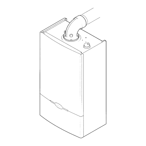
Read the instructions fully before installing or using the appliance. Description The Baxi Bahama 100 is a fully automatic gas fired wall mounted combination boiler. It is room sealed and fan assisted, and will serve central heating and mains fed domestic hot water. -
Page 5: General Layout
General Layout – page 5 Layout Backplate Airbox Fan Assembly Primary Heat Exchanger Combustion Chamber Burner Assembly & Electrodes Gas Valve Assembly Automatic Air Vent Flow Switch Heating Circuit Flow Switch DHW Circuit Circulation Pump Facia Box Safety Thermostat CH Thermostat Sensor Three Way Valve DHW Plate Heat Exchanger ON-Off Selector Switch... -
Page 6: Appliance Operation
Appliance Operation – page 6 NOTE: All delay timers mentioned in 3.1 and 3.2 are overridden by domestic hot water demand. Central Heating Mode With a demand for heating, the pump circulates water through the primary circuit. At a flow rate of approximately 125 I/hr the central heating flow switch operates, initiating the ignition sequence. -
Page 7: Technical Data
Technical Data – page 7... -
Page 8: Dimensions And Fixings
Dimensions and Fixings – page 8... -
Page 9: System Details
System Details – page 9 Information The Baxi Bahama 100 Combination Boiler is a ‘Water Byelaws Scheme - Approved Product’. To comply with the Water Byelaws your attention is drawn to the following installation requirements and notes (IRN). IRN 001 - See text of entry for installation requirements and notes. -
Page 10: Must Be Provided
System Details – page 10 Fig. 3 System Filling and Pressurising A filling point connection on the central heating return pipework must be provided to facilitate initial filling and pressurising and also any subsequent water loss replacement/refilling. The filling method adopted must be in accordance with all relevant water supply bye-laws and use approved equipment. - Page 11 System Details – page 11 Domestic Hot Water Circuit All DHW circuits, connections, fittings, etc. should be fully in accordance with relevant standards and water supply bye-laws. Your attention is drawn to: IRN 116 and Byelaw 90 and 91. Sealed primary circuits and/or secondary hot water systems shall incorporate a means for accommodating the thermal expansion of water to prevent any discharge from the circuit and/or system, except in an...
-
Page 12: Site Requirements
WARNING - The addition of anything that may interfere with the normal operation of the appliance without the express written permission of Baxi Limited could invalidate the appliance warranty and infringe the GAS Fig. 6 SAFETY (Installation and Use) REGULATIONS. - Page 13 Site Requirements – page 13 Ventilation of Compartments Where the appliance is installed in a cupboard or compartment, no air vents are required. NOTE: The ventilation label on the front of the outer case MUST NOT BE REMOVED when the appliance is installed in a compartment or cupboard.
-
Page 14: Site Requirements
Fig. 9 An internal fitting kit is available for installations where the flue terminal is inaccessible from the outside. This is available direct from Baxi Heating. Quote Part Nº 236441 when ordering. The following guidelines indicate the general requirements for siting balanced flue terminals. - Page 15 Site Requirements – page 15 Flue Dimensions Fig. 11 See Section 1.2. The standard horizontal flue kit allows for flue lengths between 200mm (7 7/8 in) and 1m (39 3/8 in) from elbow to terminal (Fig. 11). The maximum permissible equivalent flue length is: 4 metres.
- Page 16 Site Requirements – page 16 7.12 Flue Options The Baxi Bahama 100 can be fitted with flue systems as illustrated. The standard flue is suitable only for horizontal applications. Maximum permissible equivalent flue lengths are:- Horizontal 4.0 metres Vertical 4.0 metres Vertical (Twin) 22.0 metres...
-
Page 17: Installation
Installation – page 17 Initial Preparation Fig. 13 The gas supply, gas type and pressure must be checked for suitability before connection (see Section 7.6). NOTE: If the boiler is to be pre-plumbed, follow both these instructions and those on the boiler pack. - Page 18 NOTE: A small amount of water may drain from the boiler in the upright position. Baxi Limited declare that no substances harmful to health are contained in the appliance or used during construction of the appliance.
- Page 19 Installation – page 19 Fitting The Boiler Fit the central heating return filter (Fig. 18) and flow regulator (Fig. 18a). Lift the boiler using the lower edges of the combustion box. Lift the boiler over the support bracket and engage onto the top hooks (Fig.
- Page 20 Installation – page 20 Fitting The Flue HORIZONTAL FLUE The standard flue is suitable for lengths 200mm minimum to 965mm maximum (measured from the edge of the flue elbow outlet). Rear Flue: maximum wall thickness - 865mm Side Flue: maximum wall thickness - 805mm (left or right) If using the optional internal fitting kit, flue extension kit or elbows, refer to the instructions provided with the...
- Page 21 22. Fit the circular flue trim outside if required, and if necessary fit a terminal guard (see Section 7.10 & 7.11 VERTICAL FLUE Only a flue approved with the Baxi Bahama 100 can be used. For information on vertical flues consult the Baxi Bahama 100 Installer Guide or Notes for Guidance supplied with the vertical flue pack.
- Page 22 Installation – page 22 Making The Electrical Connections The electrical connections are on the left hand side of the unit. Undo the two screws securing the small cover and remove the cover (Fig. 29). Undo the two screws securing the L/N/E cable clamp and place to one side (Fig.
- Page 23 (Fig. 35). A cable clamp is provided for incoming cables. 8.10 Fitting a Programmable Room Thermostat If a Baxi Combi Controller is fitted refer to the instructions supplied with it. 8.11 Fitting a Frost Thermostat (Fig. 36) The frost thermostat is connected between positions 1 and 4.
-
Page 24: Electrical
Electrical – page 24 Schematic Wiring Diagram... - Page 25 Electrical – page 25 Illustrated Wiring Diagram...
-
Page 26: Commissioning The Boiler
10.0 Commissioning the Boiler – page 26 10.1 Commissioning the Boiler Reference should be made to BS 5449 Section 5 when commissioning the boiler. Open the cold feed to the boiler. Open all hot water taps to purge the DHW system. Ensure that the filling loop is connected and open, then open the heating flow and return valves on the boiler. - Page 27 10.0 Commissioning the Boiler – page 27 10.3 Adjusting C.H. Setting Pressure The appliance is preset to supply an output of 80,000 Btu/h (23.45 kW) for central heating. If the system design requires an output other than this, proceed as described below. Fit a pressure test gauge to the burner pressure test point (Fig.
-
Page 28: Fitting The Outer Case
11.0 Fitting the Outer Case – page 28 11.1 Fitting The Outer Case Fig. 40 Position the outercase on the chassis, ensuring that the four slots in the side flanges align with the hooks on the chassis (Fig. 40). Insert the two fixing screws into the sides of the chassis (Fig. -
Page 29: Servicing The Boiler
12.0 Servicing the Boiler – page 29 12.1 Annual Servicing Hazardous materials are not used in the construction of Baxi products, however reasonable care during service is recommended. For reasons of safety and economy, it is recommended that the boiler is serviced annually. -
Page 30: Changing Components
Hazardous materials are not used in the construction of Baxi products, however reasonable care during service is recommended. Remove the outer case and lower door panel as described under “Installation”... - Page 31 13.0 Changing Components – page 31 To change the heat exchanger - fan - burner and injector manifold - flame sensing probe -spark electrode and return electrode. Remove the airbox door panel by releasing the six ¼ turn screws (Fig. 49). Undo the four screws securing the combustion box door and remove the door (Fig.
- Page 32 13.0 Changing Components – page 32 13.6 Burner and Injector Manifold Fig. 52 Disconnect the spark, return and flame sensing electrode leads from the electrodes whilst noting their positions (Fig. 53). Loosen the lower burner securing screws and remove the upper securing screws (Fig. 52). Remove the burner (Fig.
- Page 33 13.0 Changing Components – page 33 To change the gas valve - spark generator -pump (head only) - pump - thermistor & safety thermostat - expansion vessel - pressure relief valve - flow switches - pressure gauge -diverter valve - domestic hot water filter &...
- Page 34 13.0 Changing Components – page 34 13.11 Pump If only the head needs replacing. A standard Grundfos UPS 15-60 pump head is interchangeable (see section 13.13 for details). This must be switched to setting Nº 3 (Fig. 57). 13.12 Pump (Complete) (Fig. 56) Unplug the wiring harness from the pump.
- Page 35 13.0 Changing Components – page 35 13.14 Thermistor Remove the thermistor from the flow pipe. Remove the electrical connections from the sensor. Fit the new thermistor and reassemble in reverse order. 13.15 Safety Thermostat Remove the retaining clip from the flow pipe. Remove the electrical connections from the thermostat.
- Page 36 13.0 Changing Components – page 36 13.18 Pressure Relief Valve (Fig. 62) The pressure relief valve is positioned on the central heating bypass pipe at the diverter valve manifold. Drain the system at an appropriate low point. Disconnect the union between the valve and the discharge pipe.
- Page 37 13.0 Changing Components – page 37 13.21 Diverter Valve To change the diverter valve actuator: Remove electrical plug (Fig. 65). Depress the locking latch whilst rotating the head anticlockwise through 45º (Fig. 65) and pull forward (Fig. 66). Fit the new diverter valve actuator and reassemble in reverse order.
- Page 38 13.0 Changing Components – page 38 13.22 Domestic Hot Water Filter and Flow Regulator Cartridge (Fig. 69) Isolate the cold water inlet tap. Undo the cold water inlet pipe nut. Swivel the bend to gain access to the filter and flow regulator cartridge.
- Page 39 13.0 Changing Components – page 39 13.24 Domestic Hot Water Heat Exchanger Remove the gas valve (see 13.9 Gas Valve section 1-6 incI.). Remove the cold inlet flow switch head (see Section 13.18 1-3 incI.). Remove the two screws securing the plate heat exchanger to the manifolds (Fig.
- Page 40 13.0 Changing Components – page 40 13.25 Hydraulic Control Board Remove the facia cover by removing the securing screws and pulling it forwards whilst lifting (Fig. 73). Remove all the connections from the control board (Plugs are removed by springing the retaining clip outwards and withdrawing them vertically).
-
Page 41: Short Parts List
14.0 Short Parts List – page 41 Short Parts List G.C. Description Manufacturers Part No. E02 745 Burner 241140 E02 746 Electrode - Burner 241141 E02 747 Electrode - Sensing 241142 E02 748 Electrode - Earth 241143 E02 749 Burner Manifold 241144 E02 751 Pressure Switch... -
Page 42: Fault Finding
15.0 Fault Finding – page 42... - Page 43 15.0 Fault Finding – page 43...
- Page 44 15.0 Fault Finding – page 44...
- Page 45 15.0 Fault Finding – page 45...
-
Page 46: Operational Flow Chart
16.0 Operational Flow Chart – page 46 16.1 Central Heating Mode 16.2 Domestic Hot Water... - Page 47 16.0 Operational Flow Chart – page 47...
-
Page 48: Ignition Flow Chart
17.0 Ignition Flow Chart – page 48 17.1 Ignition Phase IGNITION PHASE (From Section 16.0 Operation Flow Chart) 17.2 Overheat Lockout Procedure Non volatile lockout: The boiler waits for a manual intervention... -
Page 49: Notes
18.0 Notes – page 49... - Page 50 18.0 Notes – page 50...
- Page 51 Page 51 Baxi Limited manufacture a comprehensive range of products for the domestic heating market. Gas Central Heating Boilers (Wall, Floor and Fireside models). Independent Gas Fires. Renewal Firefronts. Gas Wall Heaters. Solid Fuel Fires. If you require information on any of these products,...
- Page 53 The Baxi Helplines - Page 52 Comp Nº 245528 – Iss 3 – 4/00 For General Enquiries +44 (0)1772 695 555 For After Sales Service +44 (0)1772 695 505 For Technical Enquiries +44 (0)1772 695 504 BAXI Baxi Limited Brownedge Road...
Need help?
Do you have a question about the Bahama 100 and is the answer not in the manual?
Questions and answers