Baxi Combi 130 HE Installation And Servicing Instructions
Gas fired wall mounted condensing combination boiler
Hide thumbs
Also See for Combi 130 HE:
- Installation and servicing instructions (64 pages) ,
- Installation & servicing instructions manual (60 pages) ,
- User operating instructions manual (12 pages)

Related Manuals for Baxi Combi 130 HE


Summary of Contents for Baxi Combi 130 HE
-
Page 1: Combination Boiler
Please leave these instructions with the user Baxi Combi 130 HE Gas Fired Wall Mounted Condensing Combination Boiler Installation and Servicing Instructions Supplied By www.heating spares.co Tel. 0161 620 6677... - Page 2 Product/Production certified by: mean continued success. Notified Body 0086. Ref: 86-BL-647 We hope you get a satisfactory service from Baxi. If For GB/IE only. not, please let us know. Baxi is a BS-EN ISO 9001 Accredited Company...
-
Page 3: Table Of Contents
Contents Section Page Introduction General Layout Appliance Operation Technical Data Dimensions and Fixings System Details Site Requirements Installation Electrical 10.0 Commissioning the Boiler 11.0 Fitting the Outer Case 12.0 Servicing the Boiler 13.0 Changing Components 14.0 Short Parts List 15.0 Fault Finding 16.0 Operational Flow Chart Supplied By www.heating spares.co Tel. -
Page 4: Introduction
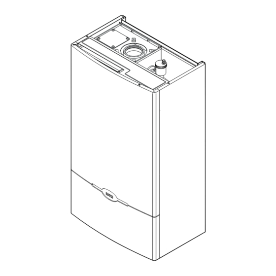
Description 1. The Baxi Combi 130 HE is a fully automatic gas Fig. 1 fired wall mounted condensing combination boiler. It is room sealed and fan assisted, and will serve central heating and mains fed domestic hot water. -
Page 5: General Layout
2.0 General Layout Layout Wallplate Flue Elbow Air Box Heat Exchanger Burner Fan Protection Thermostat Fan Assembly DHW Plate Heat Exchanger Three Way Valve Facia Box Water Pressure Gauge Gas Tap Circulation Pump Pressure Relief Valve Return Thermistor Gas/Air Ratio Valve Transformer Flow Temperature Safety Thermostat Flow Temperature Thermistor... -
Page 6: Appliance Operation
3.0 Appliance Operation NOTE: All delay timers mentioned in 3.1 and 3.2 are overridden by domestic hot water demand. Central Heating Mode 1. With a demand for heating, the pump circulates water through the primary circuit. At a flow rate of approximately 4.5 l/hr the central heating flow switch operates, initiating the ignition sequence. -
Page 7: Technical Data
IP 44 Internal Fuse Rating Pump - Available Head SEDBUK Declaration For Combi 130 HE The efficiency is 90.7% This value is used in the UK Government’s Standard Assessment Procedure (SAP) for energy rating of dwellings. The test data from... -
Page 8: Dimensions And Fixings
5.0 Dimensions and Fixings SIDE FLUE (left and right) DIMENSIONS 3° For every 1m of horizontal flue (1 in 20) A 850mm length, the clearance above the top of the flue elbow should be B 320mm 55mm to incorporate the 3° (1 in 20) fall in the flue from the C 490mm terminal to the elbow. -
Page 9: System Details
In GB it is necessary to comply with the Water Supply (Water Fittings) Regulations 1999 (or for Scotland, The Water Byelaws 2000, Scotland). The Baxi Combi 130 HE Combination Boiler is an Approved Product under the Water Regulations. To comply with the Water Regulations your attention is drawn to The Water Regulations Advisory Service (WRAS) which gives full details of the requirements. -
Page 10: Pressure Relief Valve
Check 3. For optimum operating conditions and maximum Valve Valve Valve economy the fitting of the Baxi Intellistat, is recommended. System Filling and Pressurising 1. A filling point connection on the central heating Temporary return pipework must be provided to facilitate initial... - Page 11 6.0 System Details Other Tap Domestic Hot Water Circuit Outlets 1. All DHW circuits, connections, fittings, etc. Boiler should be fully in accordance with relevant Expansion standards and water supply regulations. Vessel 2.Your attention is drawn to: for GB: Guidance G17 to G24 and recommendation R17 to R24 of the Water Check Regulations Guide.
-
Page 12: Site Requirements
7.0 Site Requirements 490mm 5mm Min 5mm Min Information 1. In GB, the installation must be carried out by a CORGI Registered Installer. It must be carried out in accordance with the relevant requirements of the Gas 200mm Safety (Installation and Use) Regulations, the appropriate Building Regulations either The Building Regulations, The Building Regulations (Scotland), Building Regulations (Northern Ireland), the Water... - Page 13 7.0 Site Requirements 3. If the boiler is fitted in a room containing a bath or shower reference must be made to the relevant requirements. In GB this is the current I.E.E. WIRING REGULATIONS and BUILDING REGULATIONS. In IE reference should be made to the current edition of IS 813 and the current ETCI rules.
- Page 14 7.0 Site Requirements Flue Terminal Position with Minimum Distance (Fig. 10) (mm) A a Directly below an opening, air brick, opening NOTE: Due to the nature of the boiler a plume windows, etc. of water vapour will be discharged from the B a Above an opening, air brick, opening window etc.
- Page 15 7.0 Site Requirements Flue Dimensions See Section 1.2. The standard horizontal flue kit allows for flue lengths between 270mm and 800mm from elbow to terminal (Fig. 11). The maximum permissible equivalent flue length is: 4 metres horizontal (Fig. 12). NOTE: Each additional 45° of flue bend will account for an equivalent flue length of 0.5m.
- Page 16 Installation Guidance Notes for each flue system type. (Documents 243501 and 243502 for concentric and twin pipe respectively). Key Accessory Size Baxi Code Number Concentric Flue System 110mm diameter Straight extension kit 1000mm 241695 500mm...
-
Page 17: Installation
It must be fitted in parallel to the existing pump and in the return pipe. See Pages 22 & 23 for wiring details. Initial Preparation Combi 130 HE The gas supply, gas type and pressure must be TEMPLATE checked for suitability before connection (see... - Page 18 Fig. 16 NOTE: A small amount of water may drain from the boiler in the upright position. Baxi declare that no substances harmful to health are contained in the appliance or used during construction of the appliance. Service Guidance Note Label on inside of panel Fig.
- Page 19 Gas connection first to centralise the boiler. The gas sealing washer is an integral part of the gas tap. The Combi 130 HE is designed to operate under nominal water supply conditions. If the Tap Rail Facia Securing...
- Page 20 Wall Thickness 8.0 Installation Fitting The Flue 3° Before fitting the flue, check the condensate (1 in 20) drain integrity (see section 8.5). IMPORTANT: The flue should always be installed with a 3° (1 in 20) fall from terminal to elbow, to allow condensate to run back to the boiler.
- Page 21 15. If necessary fit a terminal guard (see Gasket Section 7.11). VERTICAL FLUEING Only a flue approved with the Baxi Combi 130 HE Boiler can be used. For information on vertical flues consult the Fig. 26 Baxi Combination Boilers Brochure or Notes...
- Page 22 8.0 Installation Making The Electrical Connections WARNING: This appliance must be earthed. 1. The electrical connection is on the rear left hand side of the unit. Metal Shield Plug 2. Remove the electrical plug from the hardware pack. Filter 3. Connect L, N & E into the plug and connect it to the socket at the back left at the bottom of the boiler.
- Page 23 Fitting a Baxi Intellistat External Room Timer Thermostat 1. Refer to the Baxi Intellistat instructions. 2. The boiler installation parameters must be set Filter Optional Live Feed For up to recognise that the Intellistat will operate in An External Pump conjunction with the boiler (see section 10.6).
-
Page 24: Electrical
Schematic Wiring Diagram Primary Flow Overheat Fan Overheat Flow Switch Thermostat Thermostat Display PCB Condensate Trap Fan PCB Flow Return Baxi Intellistat Thermistor Thermistor Terminal Block DHW Flow Grey Switch Ribbon Cable gr gr Transformer Main PCB Flame Detection Electrode... - Page 25 9.0 Electrical Illustrated Wiring Diagram Plug Filter Pump Transformer Electrode Sensing Diverter Valve Electrode Fan Protection Thermostat Return Thermistor Flow Thermistor Gas Valve Main Flow Switch Flow Switch DHW Safety Thermostat Fan PCB Display PCB Condensate Trap Key To Wiring Colours b - Blue r - Red bk - Black...
-
Page 26: Commissioning The Boiler
Automatic Air Vent 10.0 Commissioning the Boiler 10.1 Commissioning the Boiler NOTE: The information shown on the display is explained on the label on the inside of the lower door panel (see Fig. 48). 1. Open the cold feed to the boiler. 2. - Page 27 10.0 Commissioning the Boiler 10.2 Increasing Central Heating Output To 100,000 Btu/hr 1. The boiler is factory set for a maximum output of 80,000 Btu/hr. The boiler will automatically vary its output to match the system load giving the most efficient use of gas and the most comfortable room temperature possible.
- Page 28 10.0 Commissioning the Boiler 10.3 Switching Off Intelligent Pre-heat (cont) 5. To switch the pre-heat feature back on depress the “+” and “-” Temperature Control Buttons at the same time for 5 seconds. The display will show “18 or 10” (Fig. 39). 6.
- Page 29 10.6 Switching on the Intellistat 1. For optimum efficiency, this boiler can be controlled by an optional control accessary, the Baxi Intellistat (Part No. 247495). To activate the Intellistat, the boiler installer parameter No 6 requires switching from “60” to “61”...
-
Page 30: Fitting The Outer Case
11.0 Fitting the Outer Case 11.1 Fitting The Outer Case 1. Fit the outercase to the appliance ensuring that the four slots in the side flanges align with the hooks on the chassis (Fig. 48). 2. Insert the two fixing screws into the sides of the chassis (Fig. -
Page 31: Servicing The Boiler
Also for safety, unplug the boiler at the electrical inlet socket. Hazardous materials are not used in the construction of Baxi products, however reasonable care during service is recommended. 1. For reasons of safety and economy, it is Air Box Door Panel recommended that the boiler is serviced annually. - Page 32 12.0 Servicing the Boiler 12.1 Annual Servicing (Cont) NOTE: The information shown on the display is explained on the label on the inside of the lower door panel (see Fig. 48). Burner 12. To clean the heat exchanger and burner proceed as follows: a) Disconnect the electrical leads to the fan component protection sensor (Fig.
-
Page 33: Changing Components
Also for safety, unplug the boiler at the electrical inlet socket. Hazardous materials are not used in the construction of Baxi products, however reasonable care during service is recommended. 1. Remove the outer case and lower door panel (see “Fitting the Outercase”... - Page 34 13.0 Changing Components Flowswitch 13.3 Flowswitch Flow Pipe (Fig. 58) 1. Drain the boiler (see Section 13.1 paragraph 2 & 3). 2. It may be necessary to remove the expansion vessel (see Section 13.5). 3. Remove the clip securing the flow pipe to the Clip Fig.
- Page 35 13.0 Changing Components The pump, 3-way diverter valve, pressure gauge, pressure relief valve, plate heat exchanger and DHW flow switch can be accessed after hinging down the facia box. 1. Release the facia securing screws ( turn) and hinge down the facia box (Fig. 61). 13.7 Pump (Fig.
- Page 36 13.0 Changing Components 13.10 Three-Way Diverter Valve (Head Only) (Fig. 65) If only the head needs replacing: 1. Unplug the wiring harness from the 3-way diverter valve. 2.Depress the clip and revolve the head through 30° and remove. 3. Fit replacement head and reassemble in reverse order.
- Page 37 13.0 Changing Components 13.12 Pressure Gauge (Fig. 67) Pressure Gauge Bracket 1. Drain the boiler (see Section 13.1 paragraph 2 & 3). 2. Undo the nut retaining the capillary in the connection at the return pipe (Fig. 68). 3. Depress the two lugs on either side of the pressure gauge and feed through the bracket.
- Page 38 13.0 Changing Components 13.14 DHW Plate Heat Exchanger 1. Drain the boiler (see Section 13.1 paragraph 2 & 3). 2. Remove the four screws securing the plate heat exchanger to the manifolds (Fig. 70). NOTE: Ensure nuts are not dislodged from the manifolds.
- Page 39 13.0 Changing Components The control, display and fan driver boards can be accessed on the removal of the main electrical box cover. 1. Release the facia securing screws ( turn) and hinge down the facia box. 2. Remove the screws securing the main electrical box cover (Fig.
- Page 40 13.0 Changing Components The fan and venturi, gas valve, injector pipe, condensate trap, fan protection thermostat, spark and sensing electrodes can be accessed and changed on the removal of the airbox door panel. 1. Remove the airbox door panel by loosening the four turn screws (Fig.
- Page 41 13.0 Changing Components It is necessary to remove the fan before changing the injector pipe, condensate trap and gas valve (see section 13. 21). 13.22 Injector Pipe (Fig. 78) 1. Remove the injector pipe by pulling out from the ‘O’ ring joint in the gas valve. 2.
- Page 42 13.0 Changing Components The burner and heat exchanger can be changed after removal of the combustion box door. To change the heat exchanger, the fan and burner must be removed first (see section 13. 21 & 13. 25). Burner 1. Remove the combustion box door by undoing turn securing screws.
- Page 43 13.0 Changing Components 13.27 Heat Exchanger Insulation Pads (Fig. 84) 1. Remove the fan and condensate trap (see section 13.21 and 13.24). 2. Remove the burner (see section 13. 25). 3. Remove the four bolts securing the combustion box base. 4.
-
Page 44: Short Parts List
14.0 Short Parts List Short Parts List G.C. Description Manufacturers Part No. E58 933 Flow Thermistor (Red) / Return Thermistor 240670 E58 912 Safety Thermostat (Black) / Fan Protection 242235 E06 059 Flow Switch Kit 242459 DHW Flow Switch Kit 247502 E58 989 Fan Driver PCB... -
Page 45: Fault Finding
Before performing fault finding carry out preliminary electrical checks for earth, continuity and polarity. 15.0 Fault Finding See Section 8.13 NOTE: The information shown on the display is explained on the label on the inside of the outer Go to No Display case (see Fig. - Page 46 No Display 15.0 Fault Finding Mains Input Connect Mains to Boiler. Baxi Optional External Room 230 V at A ? Ensure Plug is in Intellistat Filter Pump Timer Thermostat Socket. only Feed Link Link Check wiring from 230 V at B ? terminal block to PCB.
- Page 47 Ignition Lockout 15.0 Fault Finding Incorrect gas supply to Is 19-20 mbar dynamic at boiler. Replace Main PCB. gas valve inlet ? Is there gas but no spark? Is spark probe spark gap between 3 and wiring from Main PCB to damaged ? 4mm ? spark probe OK ?
- Page 48 Flow Temperature Overheat Lockout 15.0 Fault Finding When flow temp ≤ 60° C Replace thermostat thermostat open circuit ? (black). (measured at thermostat) Wiring from Main PCB Connections G open to thermostat faulty. circuit ? flow temp Replace flow thermistor resistance between 0.5kΩ...
- Page 49 Intellistat Fault 15.0 Fault Finding 5Vdc at connections J ? Replace Main PCB. 5Vdc Wiring Main PCB to at connections K ? boiler 3-way terminal block faulty. Transformer Flow & Return Thermistors 5Vdc Wiring boiler 3-way Mains Input at connections L ? terminal block to Room Control Faulty.
- Page 50 Diverter Valve Fault 15.0 Fault Finding No CH but DHW OK Go to External Controls section of the fault 230Vat F ? finding instructions. With DHW off & CH on, Replace Main PCB. is there 230V between P & Q ? With Black wire from Main DHW off &...
- Page 51 Fan Fault 15.0 Fault Finding 22 to 38Vdc Replace Main PCB. at connection S ? When fan on ≥ 1Vdc at Replace Main PCB. connection T ? Transformer Flow & Return Thermistors Mains Input Between Red & Blue wires from 22 &...
- Page 52 Gas Valve Fault 15.0 Fault Finding 230V at A Replace Main PCB. during ignition ? 230Vdc at B Lead from Main PCB to during ignition ? Gas Valve faulty. Replace Gas Valve. Boiler providing heat ? Transformer Flow & Return Thermistors Mains Input Replace Main PCB.
- Page 53 Dry Fire Fault 15.0 Fault Finding Is the system Fill system with water. full of water ? Connection C Replace Main PCB. short circuit when Pump on ? Wires from in-line Transformer Unplug Flow Switch, Flow & connector to PCB switch short circuit when Return faulty.
- Page 54 15.0 Fault Finding Flow Thermistor Unplug thermistor, is thermistor Replace Flow resistance between Thermistor. 0.5kΩ & 20kΩ ? Plug in thermistor, Wiring from Main PCB unplug 7-way molex, is to Flow Thermistor resistance measured at E between 0.5kΩ faulty. & 20kΩ ? Molex Replace Main PCB.
- Page 55 15.0 Fault Finding Pump Fault With a DHW tap on, Replace Main PCB. is 230V at connection H ? With a DHW tap on, Wiring from Main PCB is 230V at to Pump faulty. connection I ? Transformer Is Pump operating ? Replace Pump Head.
- Page 56 15.0 Fault Finding DHW Flow Switch Fault With power off and a Replace Main PCB. DHW tap on, is connection C short circuit ? Remove Blockage. Is DHW Flow Switch blocked ? Replace Flow Switch. Transformer Flow & Return Thermistors Mains Input Overheat Thermostats...
- Page 57 15.0 Fault Finding Fan Temperature Overheat Lockout With power off. When fan temp ≤ 60° C Replace Thermostat. thermostat open circuit ? (black) (measured at stat) With power off. Wiring from Main PCB Are connections J to Thermostat faulty. open circuit ? combustion Replace combustion chamber door seal...
- Page 58 15.0 Fault Finding External Controls Mains Input Change Main PCB. Baxi External Room Optional Intellistat Filter Timer Thermostat Pump Only Link Link Feed Is Mains Inlet Plug 230 V at A ? fitted correctly ? Kit No 247495 Check wiring from Main 230 V at B ? PCB to terminal block.
-
Page 59: Operational Flow Chart
16.0 Operational Flow Chart 16.1 Domestic Hot Water Mode DHW Flow Switch off & Flow temp above 55°C (Overrun done & DHW Flow Switch off) or (DHW Flow Switch off & Flow temp ≥ 55°C). (DHW Flow Switch off & DHW RUN DHW Flow Switch on Flow temp below 55°C &... - Page 60 16.0 Operational Flow Chart 16.2 Central Heating Mode Stabilisation done CH RUN CH STABILISATION Diverter Valve on Diverter Valve on Primary Flow Switch Pump on Pump on not made Fan Speed Variable Fan on Gas Valve on Gas Valve on Programmer off or Flame detected Programmer on &...
- Page 61 17.0 Notes Supplied By www.heating spares.co Tel. 0161 620 6677...
- Page 62 17.0 Notes Supplied By www.heating spares.co Tel. 0161 620 6677...
- Page 63 Baxi manufacture a comprehensive range of products for the domestic heating market. Gas Central Heating Boilers (Wall, Floor and Fireside models). Independent Gas Fires. Renewal Firefronts. Gas Wall Heaters. Solid Fuel Fires. If you require information on any of these products, please write, telephone or fax to the Sales Department.
-
Page 64: After Sales Service
Comp N 245736 - Iss 03 - 12/02 After Sales Service 08706 096 096 Technical Enquiries 08706 049 049 Baxi Potterton Brownedge Road Bamber Bridge Preston Lancashire PR5 6SN www.baxi.co.uk Supplied By www.heating spares.co Tel. 0161 620 6677...
Need help?
Do you have a question about the Combi 130 HE and is the answer not in the manual?
Questions and answers