
Related Manuals for Electrolux E32AR75FPS


Summary of Contents for Electrolux E32AR75FPS
- Page 1 Technical Service Manual ICON All Refrigerator and All Freezer - Professional Series Publication #5995556346 January 2010...
-
Page 3: Safe Servicing Practices For All Appliances
This service manual is intended for use by persons having electrical and mechanical training and a level of knowledge of these subjects generally considered acceptable in the appliance repair trade. Electrolux Home Products, Inc. cannot be responsible, nor assume any liability, for injury or damage of any kind arising from the use of this manual. -
Page 4: Table Of Contents
Basic Information This Manual has been prepared to provide Electrolux Service Personnel with Operation and Service Information for an Electrolux All Refrigerator and/or All Freezer Pro Units, Models Numbers E32AR75FPS, E32AF75FP, E32AR75GTT and E32AF75GT. Table of Contents Section 1 Basic Information ......... 1-1 Compressor Delay Start ........... - Page 5 Door Switch .............. 6-4 Interior Components ..........6-5 Section 7 Parts List ..........7-1 Adjustable Interior Shelves ........6-5 Models E32AF75FPS and E32AR75FPS shown Refrigerator Drawer Assembly ......6-5 All Freezer Pro Door Exploded View ......7-1 Air Filter ..............6-6 All Freezer Pro Cabinet Exploded View .....
-
Page 6: Important Safety Instructions
Proper Disposal of Refrigerators/Freezers Electrolux Home Products Inc. strongly encourages responsible appliance recycling/disposal methods. WARNING indicates a potentially hazardous Check with your utility company or visit situation which, if not avoided, could result in www.recyclemyoldfridge.com for more information... -
Page 7: Major Appliance Warranty Information
Major Appliance Warranty Information Your appliance is covered by a one year limited warranty. For one year from your original date of purchase, Electrolux will repair or replace any parts of this appliance that prove to be defective in materials or workmanship when such appliance is installed, used, and maintained in accordance with the provided instructions. -
Page 8: Model Number Breakdown
Basic Information Model Number Breakdown All Refrigerator Specifications Serial Number Breakdown... -
Page 9: Basic Information
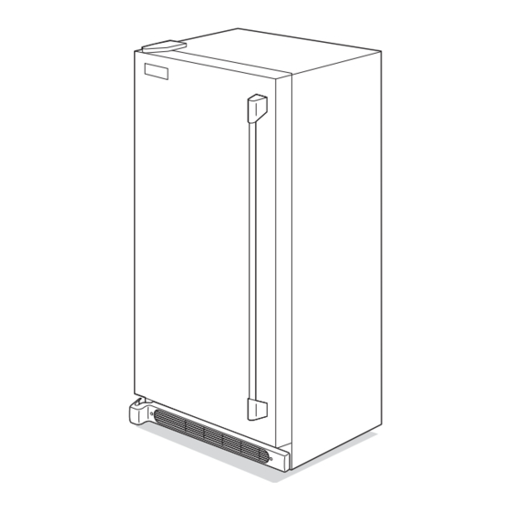
Understanding Features and Terms - All Refrigerator Professional Series Electrolux refrigerators are designed for optimal convenience and storage flexibility. The illustration below is provided to assist you with familiarizing yourself with product features and terminology. NOTE: Features may vary according to model. - Page 10 Basic Information All Freezer Specifications ®...
- Page 11 Basic Information Understanding Features and Terms - All Freezer Professional Series Electrolux freezer are designed for optimal convenience and storage flexibility. The illustration below is provided to assist you with familiarizing yourself with product features and terminology. NOTE: Features may vary according to model.
- Page 12 Basic Information Notes 1-10...
-
Page 13: Section 2 Installation
UNLESS SPECIFICALLY RECOMMENDED IN THE LITERATURE ACCOMPANYING IT. A QUALIFIED SERVICE TECHNICIAN SHOULD PERFORM ALL OTHER SERVICE. Electrolux Home Products Inc. cannot be held responsible for damage to property or injury to persons caused by failure to comply with the installation, maintenance and safety instructions contained in this... -
Page 14: Installation Checklist
Installation Information DESTROY CARTON, PLASTIC BAGS, AND ANY EXTERIOR WRAPPING MATERIAL IMMEDIATELY AFTER THE REFRIGERATOR/FREEZER IS UNPACKED. CHILDREN SHOULD NEVER USE THESE ITEMS FOR PLAY. CARTONS COVERED WITH RUGS, BEDSPREADS, PLASTIC SHEETS OR STRETCH WRAP MAY BECOME AIR TIGHT CHAMBERS AND CAN QUICKLY CAUSE SUFFOCATION. A CHILD MIGHT SUFFOCATE IF THEY CRAWL INTO THE UNIT TO HIDE OR PLAY. -
Page 15: Location
Installation Information Location 1. Choose a place that is near a grounded electrical outlet. Do Not use an extension cord or an adapter plug. 2. If possible, place unit(s) out of direct sunlight and away from range, dishwasher or other heat sources. 3. -
Page 16: Electrical Information
Installation Information If the voltage varies by 10% or more, freezer and/or Leveling Instructions For All refrigerator performance may be affected. Operating any Refrigerator/Freezer Pairs unit with insuffi cient power can damage the motor. Such damage is not covered under the warranty. If you suspect •... -
Page 17: Cut-Out Dimensions
Installation Information Cut-Out Dimensions 1. Minimum opening of 66” High x 33” Wide x 25-1/4” Deep is required for a single-unit “Built-In Look” installation. 66” Wide is required for double-unit installation. (66” High to be measured from finished floor to underside of soffit or overhead cabinet.) 2. -
Page 18: Water Supply
Installation Information Water Supply 3. Remove and discard the plastic cap from the water valve inlet at the rear of the unit. The ice maker (if equipped) requires a permanent water 4. Slide the brass compression nut, then the ferrule supply to function correctly. -
Page 19: Connecting The Water Valve To The Ice Maker
Installation Information 7. Secure the copper tube to the units’ rear panel with a steel clamp and screw. 8. Coil the excess copper tubing (about 2½ turns) behind the unit as shown. Arrange coiled tubing to avoid vibration or wear against other surfaces. 9. -
Page 20: Trim And Riser Kit Installation Instructions
Installation Information Trim And Riser Kit Installation The following items should be with the collar kit option: Instructions The Dual Trim and Riser Kit consists of the following: • Riser Kit - 2 packages • Hardware Kit - 1 bag •... -
Page 21: Setting Up The Trim And Grill Assembly
Installation Information 3. Slide grill assembly into top collar trim (A). Tape Setting Up The Trim And Grill together to prevent from sliding. (See Figure 2-12). Assembly 1. Lay the parts out on a cleared area face down. Be sure to place a drop cloth over the floor to prevent scratching trim kit and/or floor. -
Page 22: Installing Trim & Grill Assembly Into Cabinetry
Installation Information 4. Shim as necessary (shims are not included). (See Installing Trim & Grill Assembly Figures 2-17 and 2-18). Next, secure both ends Into Cabinetry of top trim (A) to cabinetry using two 3/4” mounting screws (M) through the holes at each end. Make 1. -
Page 23: Installing The Riser Kit
Installation Information Installing The Riser Kit On Early Installing The Riser Kit On Late Models Models (See Figure 2-20 to identify) (See Figure 2-21 to identify) 1. First, place a protective covering on the floor to 1. First, place a protective covering on the floor to prevent damaging either the refrigerator unit, freezer prevent damaging either the refrigerator unit, freezer unit or the floor. -
Page 24: Installation Information
Installation Information Figure 2-21. Figure 2-22. 2-12... - Page 25 Installation Information Figure 2-23. Figure 2-24. 2-13...
-
Page 26: Leveling The Refrigerator And Freezer
Installation Information Leveling The Refrigerator And Freezer 1. Remove the plastic top hinge covers and replace with the supplied silver hinge covers (I). 2. Remove the plastic toe grill panels at the bottom of each unit. Save the four screws as they will be used later in the installation. -
Page 27: Care & Cleaning Of Your Trim Kit
Installation Information Care & Cleaning Of Your Trim Kit Hinge Cover The trim and grill kit surfaces are best cleaned with a cotton cloth dampened with a mixture of water and mild 3/8” Bolts detergent. Avoid using abrasive cleaners as they will mar the surface of the metal components. - Page 28 Installation Information Notes 2-16...
-
Page 29: Section 3 Electronic Control
Electronic Control Electronic Temperature Control The electronic temperature control is located at the top center of the refrigerated compartment. Temperature is factory preset to provide satisfactory food storage temperatures. However, the temperature control is adjustable to provide a range of temperatures for personal satisfaction. -
Page 30: Initiate Diagnostics Mode
Electronic Control Initiate Diagnostics Mode Compressor Run Time (CRT) Display Mode The control will enter Diagnostics Mode when both keys When pressing both keys for 3 seconds while on setting are pressed for 3 seconds while on temperature setting “5”, the control will display the current compressor run “4”. -
Page 31: Section 4 Ice Maker
Ice Maker Side Mounted Ice Maker The Ice Maker is designed to produce ice automatically. The length of time between harvest cycles will vary, depending on load conditions, door openings, ambient temperature and freezer temperature and water temperature. These factors must be taken into consideration when checking the ice production rate. With a temperature of -2°F to +5°F in the freezer, the rate of harvest will be 40 to 96 cubes per 24 hour period. -
Page 32: Ice Maker Components
Ice Maker Water Valve Assembly Ice Maker Components The water valve is solenoid operated, and when Front Cover energized, releases water from the household supply into A decorative molded plastic front cover encloses the the ice mold. The amount of water released is directly operating mechanism of the ice maker that protects the proportional to the length of time the water valve switch mechanism from moisture. - Page 33 Ice Maker Timing Switches On/Off Switch The three timing switches used are single-pole, double A single-pole, single-throw switch is mounted on the right throw (SPDT). They are identical except for function, side of the housing at the front of the ice maker. This and can be used interchangeably.
-
Page 34: Installing Water Supply Line To Ice Maker
Ice Maker Installing Water Supply Line to Test Cycling Ice Maker Ice Maker Operation of the ice maker, water refilling, and controlled ice storage, require proper functioning and timing of all Supply line installation must comply with all applicable components. plumbing codes. -
Page 35: Operating Cycle Illustrations - Manual Cycle
Ice Maker Operating Cycle Illustrations - Manual Cycle To manually cycle ice maker: 1. Turn the On/Off switch to ON 2. Press in on switch holding the spring loaded contact set closed, this will allow the motor to start. 3. Hold in on the switch for 10 seconds to allow hold switch contacts to close allowing the ice maker to continue through a cycle. - Page 36 Ice Maker • Maker connected to electricity. • Mold temperature above 9°F. • Thermostat closes. • Motor starting. • Mold starting to heat. • Control Arm in the down position. • Feeler Arm Switch closed C to NO. • Hold Switch closed C to NC. •...
- Page 37 Ice Maker • Maker connected to electricity. • Mold temperature above 9°F. • Thermostat closed. • Motor rotating. • Mold heating. • Control Arm swinging up. • Feeler Arm Switch closed C to NC. • Hold Switch closed C to NC. •...
- Page 38 Ice Maker • Maker connected to electricity. • Mold temperature above 9°F. • Thermostat closed. • Motor starts to rotate as ice breaks loose. • Mold heating. • Control Arm is down. • Feeler Arm Switch closed C to NO. •...
- Page 39 Ice Maker • Maker connected to electricity. • Mold temperature above 9°F. • Thermostat closed. • Motor is rotating. • Mold heating. • Control Arm swinging up. • Feeler Arm Switch closed C to NO. • Hold Switch closed C to NO. •...
- Page 40 Ice Maker • Maker connected to electricity. • Mold temperature above 40°F. • Thermostat opens. • Motor is rotating. • Mold heater off. • Control Arm swinging up. • Feeler Arm Switch closed C to NC. • Hold Switch closed C to NO. •...
- Page 41 Ice Maker • Maker connected to electricity. • Mold temperature above 9°F. • Thermostat open. • Motor is rotating. • Mold heater is in series with water valve. • Control Arm swinging down. • Feeler Arm Switch closed C to NO. •...
-
Page 42: Operating Cycle Illustrations - Mechanical
Ice Maker • Maker connected to electricity. • Mold temperature above 9°F. • Thermostat open. • Motor not rotating. • Mold heater off. • Control Arm down. • Feeler Arm Switch closed C to NO. • Hold Switch closed C to NC. •... - Page 43 Ice Maker 4-13...
- Page 44 Ice Maker 4-14...
-
Page 45: Section 5 Sealed System
Federal Register May 14, 1993. Electrolux does not permit the use of recovered refrigerant in the servicing of our products for in-warranty and out-of-warranty repairs or for products covered by service contracts. Therefore, only new refrigerant or refrigerant that has been reclaimed back to new specifications by a refrigerant manufacturer is to be used. -
Page 46: Introduction
Sealed System Introduction Products using R-134a refrigerant will have a different heat exchanger than an R-12 product. The difference is This Service manual is intended as a guide for in the capillary tube, it will be longer to maintain a similar introducing the service technician to R-134a refrigerant, flow rate. -
Page 47: Service Diagnostic Tips
Sealed System Service Diagnostic Tips Refrigerator and Freezer Air Temperatures Temperatures are affected by improper door seal, frost A prime requisite on the initial contact is: Always allow accumulation on the evaporator, service load, ambient the customer to explain the problem. Many times the temperature, percent of relative humidity, thermostat trouble can be diagnosed more quickly, based on the calibration (cut-in and cut-out), location of evaporator fan... -
Page 48: Basic Components
Sealed System Basic Components Testing for Refrigerant Leaks The basic components of a refrigerated unit are a compressor, condenser, evaporator, heat exchanger The line piercing valve (clamp-on type) should be (capillary tube and suction line), drier and perimeter hot used for test purposes only. It must be removed tube. -
Page 49: Defi Nitions
Sealed System Definitions Recovery: To remove refrigerant in any condition from a system and store it in an external container without necessarily testing or processing it in any way. Recycling: To clean refrigerant for reuse by oil separation and single or multiple passes through devices, such as replaceable core filter-driers, which reduce moisture, acidity and particulate matter. -
Page 50: Low/High Side Leak Or Undercharge
Sealed System Low/High Side Leak or Precautions For Charging Sealed Undercharge Systems Overcharging a refrigeration system with refrigerant can A loss of refrigerant can result in any of the following: be dangerous. If the overcharge is sufficient to immerse the major parts of the motor and compressor in liquid 1. -
Page 51: Compressor Oil Contamination
Sealed System NEVER PRESSURIZE WITH OXYGEN. NEVER Use extreme care when using Dry Nitrogen to flush OPEN A HIGH PRESSURE TANK UNLESS IT IS systems. Pressure in nitrogen cylinder could be EQUIPPED WITH A PRESSURE REGULATOR. as high as 2000 psi. Nitrogen cylinder must be NEVER PUT HIGH PRESSURE ON THE DOME OF equipped with approved pressure regulator and THE COMPRESSOR - IT MIGHT EXPLODE. -
Page 52: Recovering Refrigerant
13 inches of vacuum. Example; for repairing Electrolux Home Products Inc. Shut system down and allow to set for two minutes. built products you will need one cylinder for R-12, one for... -
Page 53: Installing A New Compressor
Sealed System Installing a New Compressor DO NOT OPERATE RECIPROCATING COMPRESSORS WHEN CHARGING LIQUID Entirely new compressors have been developed REFRIGERANT INTO SYSTEM THROUGH ITS for use with R-134a and Ester oil refrigeration PROCESS TUBE. systems. Both compressor and electric motor have been modified. -
Page 54: Condenser Replacement
Sealed System Filter-Drier Installation 10. Solder all connections according to soldering procedure. Any time the sealed system is opened and the 11. Remove original filter-drier. refrigerant charge is removed, the liquid line fi lter-drier must be replaced and the system thoroughly evacuated before replacing refrigerant. -
Page 55: Installing Evacuation And Recharging Equipment
Sealed System 7. Cut filter-drier from condensing unit. 8. Remove sealant from cabinet where suction line R-134A SYSTEMS ARE PARTICULARLY enters. SUSCEPTIBLE TO MOISTURE CONTAMINATION 9. Remove evaporator and suction line as one piece. WHICH CAN ONLY BE PREVENTED BY 10. -
Page 56: Charging The System
Sealed System Figure 5-4. Installation of Recovery Equipment Charging The System 6. As soon as refrigerant in sight glass has gone down to predetermined level, close charging cylinder valve. Check the serial plate for the correct refrigerant type. It is extremely important to verify the type of refrigerant in the system before starting any sealed DISCONNECT THE CHARGING CYLINDER HEATER system repairs. -
Page 57: Dedicated Equipment
Sealed System Dedicated Equipment Robinair has stated that their current and discontinued vacuum pump models, using mineral oil currently R-134a must not be mixed with other types of specified for use in their vacuum pumps, can be used to evacuate R-134a/Ester oil systems. Robinair also states refrigerants. -
Page 58: Spills Or Leaks
Sealed System Spills or Leaks If a large release of vapor occurs, such as from a large spill or leak, the vapors may concentrate near the floor or low spots and displace the oxygen available for breathing, causing suffocation. Evacuate everyone until the area has been ventilated. Use blowers or fans to circulate the air at floor level. -
Page 59: Inhalation Toxicity
Sealed System HFC 134a COMPARISON WITH CFC 12 HFC 134a (1,1,1,2-tetrafluoroethane) is being studied as part of the PAFT I programme sector, which began in December 1987. It is a prime candidate for the replacement of CFC 12 (dichlorodifluoromethane) in refrigeration and air conditioning systems, medical aerosols, and in certain foam blowing applications. -
Page 60: Combustibility Of Hfc-134A
Sealed System Combustibility of HFC-134a Filling and Charging Operations HFC-134a is nonflammable at ambient temperatures • Before evacuating cylinders or refrigeration and atmospheric pressure. However, tests have shown equipment, any remaining refrigerant should be HFC-134a to be combustible at pressures as low as 5.5 removed by recovery system. -
Page 61: R-134A Physical Properties
Sealed System R-134a Physical Properties: R-134a - Tetrafluoroethane Refrigerant of choice in automotive industry. Genetron134a replaces CFC12 for air conditioning and refrigeration systems in commercial residential and industrial applications. R-12 - Dichlorodifluoromethane A versatile and widely used refrigerant. Common in reciprocating and rotary type equipment. For all types of appli- cations, household to industrial. -
Page 62: Hfc-134A, Cfc-12 Pressure Temperature Chart
Sealed System HFC-134a, CFC-12 Pressure Temperature Chart 5-18... - Page 63 Sealed System CFCs Chlorofluorocarbons (CFCs) are compounds consisting of chlorine, fluorine, and carbon atoms which are very stable in the troposphere. They are degraded only in the stratosphere by the sun’s radiation where released chlorine may contribute to ozone depletion. They can persist in the troposphere for a hundred years or longer. Fluorocarbons These chemical compounds include CFCs, hydrochlorofluorocarbons (HCFCs), and hydrofluorocarbons (HFCs).
- Page 64 Sealed System HCFCs Hydrochlorofluorocarbons (HCFCs) are compounds comprised of hydrogen, chlorine, fluorine, and carbon atoms. These compounds have many of the useful properties of CFCs, but are destroyed naturally in the lower atmosphere and do not persist to the same extent as CFCs. Only a fraction of HCFCs emitted can be transported to the ozone layer in the stratosphere where their chlorine could deplete ozone.
-
Page 65: Section 6 Component Teardown
Component Teardown Component Teardown This section explains how to access and remove components from an Electrolux ICON Built-In All Refrigerator Pro and/or a Built-In All Freezer Pro unit, and has been arranged in such a way as to simulate which components would need to be removed fi... -
Page 66: Refrigerator Exterior Components
Component Teardown Refrigerator Exterior Components Door Handle Removal The door handle is secured with setscrews to the handle mounting shoulder screws that are fastened into the front of the door assembly. To remove the handle, use a 3/32” allen wrench and extract the two setscrews located in each handle standoff. -
Page 67: Door Stop Assembly
Component Teardown Door Stop Assembly Removal Door Frame The door stop is secured to with two screws the Screws underside of the door assembly. To remove the door stop: Door Stop 1. Remove door from unit. 2. Extract the two screws securing the door stop to the bottom of the door assembly. -
Page 68: Adjustable Door Bins
Component Teardown Adjustable Door Bins Removal There are four two liter door bins that can be arranged as needed by the user. To remove a two liter door bin, lift the bin straight up until it is free of the supports molded into the door liner, then pull from unit. -
Page 69: Interior Components
Component Teardown Interior Components Adjustable Interior Shelves Multi-position adjustable interior shelves can be moved to any position for larger or smaller packages. The can- tilever shelves are supported at the back of the refrigerator. (See Figure 6-10) Replace the shelf by inserting the hooks at rear of the shelf into the wall bracket. -
Page 70: Air Filter
Component Teardown Air Filter Removal Push the plastic bubble tab at the back of the control box housing. This releases the hinged bottom half to drop open. Remove the old filter and discard it. Unpackage the new filter and place it inside the hinged bottom half of the housing. -
Page 71: Control
Component Teardown Control Removal Screws To remove the control: 1. Disconnect power from unit. Control Box 2. Remove control box from refrigerated compartment. 3. Extract the two screws securing the control to the control box. (See Figure 6-15) 4. Pull the front of the control box away from the Control control while pulling the control up and out from its installation position. -
Page 72: Baffl E Plate
Component Teardown Baffle Plate Removal To remove the baffl e plate, with one hand grab the baffl e plate from the center and pull back while with the other hand, reach behind to disengage the retaining latches. (See Figure 6-18) Evaporator Cover Removal The evaporator cover is secured with screws to the Baffle Plate... -
Page 73: Thermistor
Component Teardown Thermistor Removal Electrical Connection The evaporator cover does not need to be completely Thermistor removed to access the thermistor wire harness Screw connections and mounting screw, however, removing the evaporator cover from the unit will make the task easier. To remove the thermostat control: Ground Wire... -
Page 74: Defrost Thermostat
Component Teardown Defrost Thermostat Removal Disconnect Here The defrost thermostat is secured with a retaining clip to the upper left corner of the evaporator assembly. The defrost thermostat and wire harness connections may be accessed without completely removing the evaporator Defrost cover. - Page 75 Component Teardown Evaporator Removal The evaporator sets upon the two screw standoffs mounted to the back wall of the freezer compartment. Two pieces of styrofoam are pressed between the evaporator assembly and the sidewalls of the unit, securing the assembly in position. (See Figure 6-25) Screw Standoffs To remove the evaporator: 1.
-
Page 76: Compressor Area Components All Refrigerator And All Freezer-Pro Models
Component Teardown Compressor Area Components All Refrigerator and All Freezer-Pro Models The compressor area components for the All Refrigerator and All Freezer-Pro Units are similar in layout and have the same access and removal steps. However, the part numbers for items in the compressor area may differ between the all refrigerator and all freezer models. -
Page 77: Theater Lighting Control
Component Teardown Theater Lighting Control Removal Door Switch The theater lighting control is mounted to the lower left interior side wall in the compressor area. The control Electrical may be accessed from the front but is easier to access Screws Connection from the rear of the unit. - Page 78 Component Teardown Compressor Removal Bolt Spring Wire The compressor sits on four grommets and is secured with four screws to the compressor mounting plate. (See Figure 6-30) To remove the fi lter-drier: 1. Pull unit from its installation position to access the Capacitor rear compressor area.
- Page 79 Component Teardown Drain Pan Removal The drain pan is secured with four screws to bottom of the unit frame. To remove the drain pan: 1. Pull unit from its installation position to access the rear compressor area. Disconnect power from unit. 2.
- Page 80 Component Teardown Condenser Coil Removal Cut Here The condenser coil is mounted to the drain pan by four retaining clips. To remove the drain pan: 1. Pull unit from its installation position to access the rear compressor area. Disconnect power from unit. 2.
-
Page 81: Freezer Exterior Components
Component Teardown Freezer Exterior Components Door Handle Removal The door handle is secured with setscrews to the handle mounting shoulder screws that are fastened into the front of the door assembly. To remove the handle, use a 3/32” allen wrench and extract the setscrew located in each handle standoff. -
Page 82: Door Bin
Component Teardown Door Bin Removal There are two door bins that can be arranged as needed by the user. To remove a door bin, lift the bin straight up until it is free of the supports molded into the door liner, then pull from unit. -
Page 83: Door Gasket And Inner Panel
Component Teardown Door Gasket and Inner Panel Removal Outer Door The inner panel of the door assembly is secured with Panel screws that pass through the inner panel and fasten into the door assembly. The door gasket has an inner lip that is pressed between the inner panel and the door assembly and is secured in position when the inner panel screws are fastened to the door assembly. -
Page 84: Interior Components
Component Teardown Interior Components Adjustable Interior Shelves Multi-position adjustable interior shelves can be moved to any position for larger or smaller packages. The cantilever shelves are supported at the back of the refrigerator. (See Figure 6-43) Replace the shelf by inserting the hooks at the rear of the shelf into the wall bracket. -
Page 85: Air Filter
Component Teardown Air Filter Removal Push the plastic bubble tab at the back of the control box housing. This releases the hinged bottom half to drop open. Remove the old filter and discard it. Unpackage the new filter and place it inside the hinged bottom half of the housing. -
Page 86: Baffl E Plate
Component Teardown Baffle Plate Removal To remove the baffl e plate, remove any shelves that block access to the baffl e. Then push towards the center from one end while pulling away from the back wall. (See Figure 6-48) Ice Maker Removal Baffle Plate The icemaker is mounted with two 1/4”... -
Page 87: Mid Level Lighting
Component Teardown Mid Level Lighting Removal The mid level lighting components may be accessed without the evaporator cover being completely removed from the compartment. By pulling the top of evaporator cover away from the rear wall, the light wire harness connections and light fi... -
Page 88: Evaporator Fan Assembly
Component Teardown Evaporator Fan Assembly Removal The evaporator fan assembly consists of the fan motor mount bracket, fan motor and fan blade. Two screws Fan Blade Fan Motor secure the fan motor to the fan motor mount bracket. The evaporator fan assembly is then secured with two screws to the back wall of the freezer compartment. -
Page 89: Defrost Heater
Component Teardown Defrost Heater Removal Disconnect Here The defrost heater is secured with two aluminum straps to the bottom tube of the evaporator assembly. (See Figure 6-55) To remove the defrost heater: 1. Disconnect power from unit. Styrofoam 2. Remove the adjustable shelves. Styrofoam 3. - Page 90 Component Teardown Notes 6-26...
-
Page 91: Section 7 Parts List
Parts List All Freezer Pro Door Exploded View Model E32AF75FPS Ref # Part # Description 216522309 Gasket-door, white Functional Parts 216527902 Panel-inner door, frzr 297316549 Panel-outer door, stainless, LH Non-Illustrated Parts 241603101 Label, nameplate, elux/icon 216974400 Door Stop 241637912 Handle Assembly, stainless, w/endcaps 241601001 Wrench, allen 5304460608... -
Page 92: All Freezer Pro Cabinet Exploded View
Parts List All Freezer Pro Cabinet Exploded View Model E32AF75FPS... -
Page 93: Parts List
Parts List Ref # Part # Description 216503100 Screen-drain 297259600 Fan Blade, evaporator 297200600 Breaker Kit w/corners, no lock slot 297200100 Breaker Kit w/corners, 32”, top and bottom 13 # 297250000 Motor, fan, 115 V 216822900 Switch, light/lamp, ramp 297048600 Light Bulb/Lamp, short 297139501 Socket, light/lamp, 25 W... -
Page 94: All Freezer Pro System Exploded View
Parts List All Freezer Pro System Exploded View Model E32AF75FPS... - Page 95 Parts List Ref # Part # Description 297152200 Condenser, dynamic 5308000110 Strap-evap/heater, aluminum, (2) 216987500 Drier-filter 297171400 Harness-main 14 # 216730700 Heater-defrost 15 # 216997300 Evaporator 297217900 Heat Exchanger, suct/cap tube 297114000 Light Bulb, short, blue tint, 40W 241507803 Socket-light 297110300 Box-control, front 297078701...
-
Page 96: Ice Maker Exploded View
Parts List Ice Maker Exploded View Model E32AF75FPS... - Page 97 Parts List Ref # Part # Description 297044902 Tube-water inlet, inlet valve, to ice maker 240561701 Seal-water inlet, inlet valve, to ice maker 5304456650 Spring-shutoff arm, ice maker 5304456657 Nameplate Functional Parts 5304456658 Gear Non-Illustrated Parts 5304456659 Plate-mounting 5304456691 Screw, M 3x20 #3, valve plate 5304445222 Motor-ice maker Svo 5304445223...
-
Page 98: All Refrigerator Pro Door Exploded View
Parts List All Refrigerator Pro Door Exploded View Model E32AR75FPS... - Page 99 Parts List Ref # Part # Description 216522309 Gasket-door, white 240338313 Door, dairy, clear 216953601 Panel-inner door, refr 297316548 Panel-outer door, stainless, RH 241603101 Label, nameplate, elux/icon 5303271076 Door Stop 241637912 Handle Assembly, stainless, w/endcaps 241601001 Wrench, allen 5304460608 Screw, flat head, #1/4-20, door stop/hng 216524201 Gasket, secondary 5304472186...
-
Page 100: All Refrigerator Pro Cabinet Exploded View
Parts List All Refrigerator Pro Cabinet Exploded View Model E32AR75FPS 7-10... - Page 101 Parts List Ref # Part # Description 216503100 Screen-drain # Functional Parts 297259600 Fan Blade, evaporator * Non-Illustrated Parts 297200600 Breaker Kit w/corners, no lock slot 297200100 Breaker Kit w/corners, 32”, top and bottom 13 # 297250000 Motor, fan, 115 V 216822900 Switch, light/lamp, ramp 297048600...
-
Page 102: All Refrigerator Pro System Exploded View
Parts List All Refrigerator Pro System Exploded View Model E32AR75FPS 7-12... - Page 103 Parts List Ref # Part # Description 297152200 Condenser, dynamic # Functional Parts 5308000110 Strap-evap/heater, aluminum, (2) * Non-Illustrated Parts 216938600 Drier-filter 297171500 Harness-main 14 # 216730700 Heater-defrost 15 # 216997300 Evaporator 297319400 Heat Exchanger 297114000 Light Bulb, short, blue tint, 40W 241507803 Socket-light 297108000...
- Page 104 Parts List Notes 7-14...
-
Page 105: Section 8 Troubleshooting
Troubleshooting Cause Correction Problem Freezer/refrigerator Unit is plugged into a circuit that has a Use another circuit. Check circuit for proper compressor does not ground fault interrupt. voltage. run. Temperature control is in the “OFF” Set control to a temperature setting. Instruct position. - Page 106 Troubleshooting Problem Cause Correction Louder sound levels Modern Freezers have increased This is normal. When the surrounding noise whenever Freezer/ storage capacity and more stable level is low, you might hear the compressor refrigerator is on. temperatures. They require heavy duty running while it cools the interior.
- Page 107 Troubleshooting The following table relates to troubleshooting the thermostat, electronic components and compressor with its associated components. Cause Correction Problem Compressor and 1. Is the temperature control set to Yes. Set control from 1 to 7 off? No. Go to step 3. evaporator fan motor does not run.
- Page 108 Troubleshooting Notes...
-
Page 109: Section 9 Wiring Schematics
Wiring Schematics Ice Maker Schematic... -
Page 110: All Freezer Pro Wiring Diagram
Wiring Schematics All Freezer Pro Wiring Diagram... -
Page 111: All Refrigerator Pro Wiring Diagram
Wiring Schematics All Refrigerator Pro Wiring Diagram... - Page 112 Wiring Schematics Notes...
Need help?
Do you have a question about the E32AR75FPS and is the answer not in the manual?
Questions and answers