Table of Contents
Advertisement
Advertisement
Table of Contents

Related Manuals for Clevo D4F


Summary of Contents for Clevo D4F
-
Page 3: Trademarks
Preface Notice The company reserves the right to revise this publication or to change its contents without notice. Infor- mation contained herein is for reference only and does not constitute a commitment on the part of the man- ufacturer or any subsequent vendor. They assume no responsibility or liability for any errors or inaccuracies that may appear in this publication nor are they in anyway responsible for any loss or damage resulting from the use (or misuse) of this publication. -
Page 4: Fcc Statement
Preface FCC Statement (Federal Communications Commission) This equipment has been tested and found to comply with the limits for a Class B digital device, pursuant to Part 15 of the FCC Rules. These limits are designed to provide reasonable protection against harmful interference in a residential installation. -
Page 5: Important Safety Instructions
Preface IMPORTANT SAFETY INSTRUCTIONS Follow basic safety precautions, including those listed below, to reduce the risk of fire, electric shock and injury to persons when using any electrical equipment: Do not use this product near water, for example near a bath tub, wash bowl, kitchen sink or laundry tub, in a wet basement or near a swimming pool. -
Page 6: Instructions For Care And Operation
Preface Instructions for Care and Operation The computer is quite rugged, but it can be damaged. To prevent this, follow these suggestions: Don’t drop it, or expose it to shock. If the computer falls, the case and the components could be damaged. - Page 7 Preface Avoid interference. Keep the computer away from high capacity transformers, electric motors, and other strong magnetic fields. These can hinder proper performance and damage your data. Follow the proper working procedures for the computer. Shut the computer down properly and don’t forget to save your work.
-
Page 8: Power Safety
Preface Power Safety The computer has specific power requirements: • Only use a power adapter approved for use with this computer. • Your AC adapter may be designed for international travel but it still requires a steady, uninterrupted power supply. If you are unsure of your local power specifi- Power Safety cations, consult your service representative or local power company. -
Page 9: Battery Precautions
Preface Battery Precautions • Only use batteries designed for this computer. The wrong battery type may explode, leak or damage the com- puter. • Do not continue to use a battery that has been dropped, or that appears damaged (e.g. bent or twisted) in any way. -
Page 10: Cleaning
Preface Cleaning Do not apply cleaner directly to the computer, use a soft clean cloth. Do not use volatile (petroleum distillates) or abrasive cleaners on any part of the computer. Servicing Do not attempt to service the computer yourself. Doing so may violate your warranty and expose you and the computer to electric shock. -
Page 11: Travel Considerations
Preface Travel Considerations Packing As you get ready for your trip, run through this list to make sure the system is ready to go: Check that the battery pack and any spares are fully charged. Power off the computer and peripherals. Close the display panel and make sure it’s latched. - Page 12 Preface On the Road In addition to the general safety and maintenance suggestions in this preface, and Chapter 8: Troubleshoot- ing, keep these points in mind: Hand-carry the computer - For security, don’t let it out of your sight. In some areas, computer theft is very common.
- Page 13 Preface Developing Good Work Habits Developing good work habits is important if you need to work in front of the computer for long periods of time. Improper work habits can result in discomfort or serious injury from repetitive strain to your hands, wrists or other joints.
- Page 14 Preface Lighting Proper lighting and comfortable display viewing angle can reduce eye strain and muscle fatigue in your neck and shoulders. • Position the display to avoid glare or reflections from overhead lighting or outside sources of light. • Keep the display screen clean and set the brightness and contrast to levels that allow you to see the screen clearly.
-
Page 15: Table Of Contents
Preface Contents PC Camera ............1-7 LCD Panel ............1-7 Notice ................I Microphone ............1-7 Trademarks ............I LED Power & Communication Indicators ... 1-7 FCC Statement ...........II LED Status Indicators ........... 1-7 Instructions for Care and Operation ....IV Hot-Key Buttons ........... - Page 16 Preface Vent ..............1-16 LED Power & Communication Indicators .... 2-6 DC-In Jack ............1-16 Auto Mail Checker ........... 2-7 2 USB 2.0 Ports ...........1-17 Special Group ............2-9 External Monitor (VGA) Port ......1-17 Hard Disk Drive ............. 2-10 Printer/Parallel Port ..........1-17 Optical Device Bay ..........
- Page 17 Preface Advanced Controls Hibernate ............3-25 Configuring the Power Button ......3-26 Overview ..............3-1 Battery Information ..........3-27 Advanced Video Controls ........3-2 New Battery ............3-27 Opening the LCD ...........3-2 Battery Life ............3-27 Video Driver Controls ..........3-3 Battery FAQ ............3-28 Making Adjustments for the Display .....3-4 Configuring the Infrared Settings for FIR .....
- Page 18 Preface Hot-Key (Win2000) ..........4-9 Failing the POST ........... 5-4 TouchPad (Win2000) ...........4-10 Fatal Errors ............5-4 PC Card/PCMCIA (Win2000) ......4-10 Non-Fatal Errors ........... 5-4 PC Camera (Win2000) .........4-10 The Setup Program ..........5-5 Wireless LAN (Win2000) ........4-10 Entering Setup ............5-5 Bluetooth (Win2000) ...........4-10 Setup Screens ............
- Page 19 Preface Wireless LAN Driver Installation (Win2000) ..7-3 Wireless LAN & Bluetooth Modules ....8-15 Wireless LAN Driver Installation (WinXP) ..7-4 OS and Driver Installation ........8-16 Bluetooth Driver Installation (Win2000) ....7-5 Hyper-Threading Notes ......... 8-17 Bluetooth Driver Audio Setup (Win2000) .....7-6 Specifications Bluetooth Driver Installation (WinXP) ....7-7 Processor Types ..........
- Page 20 Preface Optional ............... A-6 XVIII...
-
Page 21: Introduction
Introduction Chapter 1: Introduction Overview Notes This manual refers to the hardware and essential software required to run your Check the light colored computer. Depending on how your system is configured, some or all of the boxes with the mark above to find detailed features described may already be set up. -
Page 22: Warning Boxes
Introduction Warning Boxes No matter what your level please pay careful attention to the warning and safe- ty information indicated by the symbol. Also please note the safety and handling instructions as indicated in the Preface . Not Included Operating Systems (e.g. Windows 2000 Professional, Windows XP etc.) have their own manuals, as do applications (e.g. -
Page 23: Quick Start Guide
Introduction Quick Start Guide This guide assumes that you are already familiar with computers and can tell at a glance what and where all the key components are. If you are not that com- Peripheral Devices fortable with this type of device, then please refer to the following pages, Please note that pe- which give an overview of the system. -
Page 24: System Map
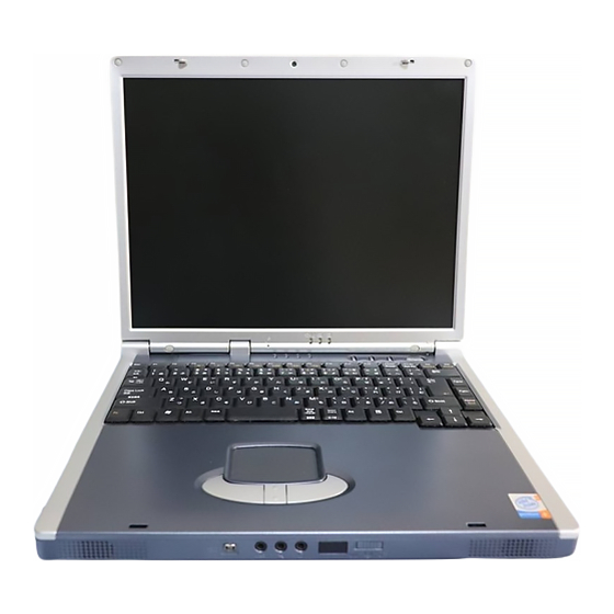
Introduction System Map Your computer has a lot of built-in features. Most of these are enabled by your operating system. Further explanations of the various subsystems are covered Design Types in the chapter or pages indicated. This manual refers to Getting to Know Your Computer the notebook designs pictured on this page. -
Page 25: Top View
Introduction Top View Figure 1 - 1 Top View with LCD Panel Closed LCD Latches LED Power & Communication Indicators To open the LCD display: Place the computer on a stable surface. Move the LCD latches in the direction of the arrows to release the top cover. -
Page 26: Top View With Lcd Panel Open
Introduction Top View with LCD Panel Open Figure 1 - 2 Top View with LCD Panel Open (Design Differences) Optional PC Camera Built-In Microphone LED Power & Communication Indicators LED Status Indicators Hot-Key buttons Close Cover Switch Power Button Keyboard 10. -
Page 27: Pc Camera
Introduction PC Camera The PC Camera will allow you to capture video files to .avi format. Make sure you install the driver and software, then run the software by selecting the AM- CAP program (see “PC Camera” on page 7 - 10). -
Page 28: Hot-Key Buttons
Introduction Hot-Key Buttons The three hot-key buttons allow you instant access to your default Internet browser, default e-mail program, and an application of your choice. To learn how to set the buttons, see “Hot-Key Buttons” on page 2 - Close Cover Switch This switch acts as a sensor to tell when the LCD Panel is closed. -
Page 29: Keyboard
Introduction Keyboard The computer has a “Win Key” keyboard including a numeric keypad. It has the same features as a full-sized desktop keyboard and can easily be replaced Forced Off with a different language keyboard should you desire. If the system “hangs”, and the Ctrl + Alt + Del TouchPad &... -
Page 30: Front View
Introduction Front View Figure 1 - 3 Front View LCD Latches Mini-IEEE 1394 Port S/PDIF Out Port Microphone-In Jack Headphone-Out Jack Infrared Transceiver Wireless Module ON/OFF Switch Built-In Speakers IEEE 1394 The Mini-IEEE 1394 port only supports SELF POWERED IEEE 1394 devices. Infrared Communication The Infrared transceiver operates on a “Line of Sight”. -
Page 31: Mini-Ieee 1394 Port
Introduction Mini-IEEE 1394 Port This allows high-speed connection to various peripheral devices, e.g. external disk drives and digital cameras. S/PDIF Out Port This S/PDIF (Sony/Philips Digital Interface Format) Out Port allows you to connect your DVD-capable PC to a Dolby AC-3 compatible receiver for “5.1” or ‘dts’... -
Page 32: Wireless Module On/Off Switch
Introduction Wireless Module ON/OFF Switch If you have purchased the optional Wireless LAN and/or Bluetooth mod- ule(s), you can use this switch to turn the module(s) ON or OFF. To enable the module(s) you will need to install the drivers/software for it/them. You can use the key combination Fn + F12 to toggle power to the modules if you have two modules installed (see “Wireless LAN &... -
Page 33: Left Side View
Introduction Left Side View Figure 1 - 4 Left Side View Optical Device Bay 7-in-1 Card Reader PC Card Slot PC Card Slot Eject Optical Device Bay Button The optical device bay will contain a 5.25" (12.7mm height) CD/DVD device. The actual device type will depend on the option you purchased (see “Storage Devices”... -
Page 34: 7-In-1 Card Reader
Introduction 7-in-1 Card Reader The card reader allows you to use the most popular digital storage cards. Refer “7-in-1 Card Reader Module” on page 2 - 16 for more information. Operating System Installation Warning PC Card Slot If you are installing an The 3.3V/5V slot may be used for a Type-II PC card (PC cards were also pre- Operating System... -
Page 35: Right Side View
Introduction Right Side View Figure 1 - 5 Right Side View Security Lock Slot Security Lock Slot To prevent possible theft, a Kensington-type lock can be attached to this slot. Locks can be purchased at any computer store. Right Side View 1 - 15... -
Page 36: Rear View
Introduction Rear View Figure 1 - 6 Rear View 8 9 10 Vent DC-In Jack 2 USB 2.0 Ports External Monitor (VGA) Port Overheating Parallel Port Serial Port To prevent your com- S-Video Out Port puter from overheating make sure nothing PS/2 Type Port blocks the vent/fan in-... -
Page 37: Usb 2.0 Ports
Introduction 2 USB 2.0 Ports These USB 2.0 compatible ports (USB 2.0 is fully USB 1.1 compliant) are for low-speed peripherals such as keyboards, mice or scanners, and for high- speed peripherals such as external HDDs, digital PC cameras or high-speed scanners etc. -
Page 38: S-Video Out Port
Introduction S-Video Out Port Connect your television to your computer and view DVDs, VCDs or anything else your computer can display. You will need an S-Video cable to make the connection. Enable this port from the video driver controls (see “TV Display”... -
Page 39: Bottom View
Introduction Bottom View Figure 1 - 7 Bottom View Vent/Fan Intake Battery Cover Hard Disk Cover Bluetooth Module Cover The CPU is not a user serviceable part. CPU & Memory Opening this compart- Socket Cover ment, or accessing the Note: The RAM and option- CPU in any way, may al Wireless LAN module are violate your warranty. -
Page 40: Hard Disk Drive
Introduction Hard Disk Drive The internal hard disk drive is used to store your data. See information on page 6 - 4 for information on upgrading/replacing your hard disk drive. Wireless LAN & Bluetooth Modules The Wireless LAN and Bluetooth modules Drive Warning may be enabled and... -
Page 41: Using The Computer
Using The Computer Chapter 2: Using The Computer Overview To learn more about using your computer, please read this chapter. This chapter includes: • The Power Sources • Turning on the Computer • The LED Indicators • The Auto Mail Checker •... -
Page 42: The Power Sources
Using The Computer The Power Sources The computer can be powered by either an AC adapter or a battery pack. Power Button as Standby or Hibernate AC Adapter Button Use only the AC adapter that comes with your computer. The wrong type of If you are using a fully AC adapter will damage the computer and its components. -
Page 43: Recharging The Battery With The Ac Adapter
Using The Computer Recharging the Battery with the AC Adapter The battery pack automatically recharges when the AC adapter is attached and plugged into an electrical outlet. If the computer is powered on, and in use, it will take several hours to fully recharge the battery. When the computer is Battery Removal turned off but plugged into an electrical outlet, battery charge time is less. -
Page 44: Turning On The Computer
Using The Computer Turning on the Computer Now you are ready to begin using your computer. To turn it on simply press the power button on the front panel. Shutdown Note that you should When the computer is on, you can use the power button as a Standby/Hiber- always shut your com- nate/Shutdown hot-key button when it is pressed for less than 4 seconds puter down by choos-... -
Page 45: Led Indicators
Using The Computer LED Indicators There are two sets of LED indicators (LED Power & Communication Indi- cators and LED Status Indicators) on your computer that will display help- ful information about the current status of the computer. The LED Power & Communication Indicators are also visible when the top of your computer is closed. -
Page 46: Led Power & Communication Indicators
Using The Computer LED Power & Communication Indicators Icon Color Description Battery Problem Orange AC Adapter is plugged in If the battery has a se- Green The computer is on rious problem contact Blinking Green The computer is in standby mode your service represen- tative. -
Page 47: Auto Mail Checker
Using The Computer Auto Mail Checker After you have installed the driver for the Auto Mail program (see “What to Install” on page 4 - 1) you may then configure it to give you notification when you receive new mail. You must be online to receive this notification (note that this program only supports the POP3 protocol), and your default mail program does not need to be open. - Page 48 Using The Computer You may then configure the options for your mailserver, name, password, pro- gram and method(s) of notification. Note Check with your Inter- net Service Provider, network administrator or Mail Service provid- er for details on what to put on these pages.
-
Page 49: Special Group
Using The Computer Special Group You may add the e-mail addresses of those you wish to assign to your special group here. The Mail LED will then blink fast when mail is received from members of this group, if LED notification is enabled in the control panel (Figure 2 - Figure 2 - 5 Special Group Setup... -
Page 50: Hard Disk Drive
Using The Computer Hard Disk Drive The hard disk drive is used to store your data in the computer. The hard disk can be taken out to accommodate other 2.5" IDE hard disk drives with a height Power Safety of 9.5 mm. Before attempting to access any of the inter- The hard disk... -
Page 51: Optical Device Bay
Using The Computer Optical Device Bay The optical device bay will contain a 5.25" CD-ROM/DVD type optical de- vice. The actual device type will depend on the option you purchased (see Sound Volume Adjustment “Storage Devices” on page A - 3). -
Page 52: Handling Cds Or Dvds
Using The Computer Handling CDs or DVDs Proper handling of your CDs/DVDs will prevent them from being damaged. Please follow the advice below to make sure that the data stored on your CD- CD Emergency Eject ROMs/DVD-ROMs can be accessed. If you need to manually Remember to: eject a CD (e.g. -
Page 53: Dvd Regional Codes
Using The Computer DVD Regional Codes DVD region detection is device dependent, not OS-dependent. You can select your module’s region code 5 times. The fifth selection is permanent. This can- not be altered even if you change your operating system or you use the module in another computer. -
Page 54: Changing Dvd Regional Codes
Using The Computer Changing DVD Regional Codes Go to the Control Panel in WindowsXP/Windows 2000 and double-click Sys- tem > Hardware (tab), click Device Manager, then click the + next to DVD/ CD-ROM drives. Double-click on the DVD-ROM device to bring up the Properties dialog box, and select the DVD Region (tab) to bring up the con- trol panel as seen in “DVD Regional Codes (Windows XP)”... -
Page 55: Pc Card Slot
Using The Computer PC Card Slot The computer is equipped with a PCMCIA 3.3V/5V slot for one Type II PC Card. Make sure you install the driver for the PC Card (see “What to Install” on page 4 - Inserting and Removing PC Cards •... -
Page 56: 7-In-1 Card Reader Module
Using The Computer 7-in-1 Card Reader Module The card reader allows you to use the most popular digital storage cards. The formats which can be read include: Operating System Installation Warning • MMC (MultiMedia Card) • SD (Secure Digital) If you are installing an Operating System •... -
Page 57: Hot-Key Buttons
Using The Computer Hot-Key Buttons These keys access the internet, e-mail or a user-defined application with one quick button press. To use the “user-defined Hot-Key”, you must install the Hot-Key driver. Refer to “What to Install” on page 4 - 1 for driver installation steps. - Page 58 Using The Computer To configure and specify an application for Application 1 (the default Hot- Key button setting is for the CD Player/Media Player application), you must follow the instructions below. Application.exe Right click the Hot-Key driver icon on the taskbar and the following You will need to locate menu will appear.
-
Page 59: Function Keys & Numeric Keypad
Using The Computer Function Keys & Numeric Keypad Function Keys Other Keyboards On the bottom-left of the keyboard is the Fn key or Function key. The Fn key If your keyboard is allows you to change operational features instantly. To use the functions press damaged or you just and hold the Fn key, then press the appropriate function key (F3 - F9 etc.) lo- want... -
Page 60: Numeric Keypad
Using The Computer Numeric Keypad The keyboard has an embedded numerical keypad for easy numeric data input. The numeric keys are highlighted by a yellow typeface. Special Characters Activate the Number Lock feature by pressing and holding the Fn key, then Some software appli- press the NumLk key at the top right of the keyboard. -
Page 61: Touchpad & Buttons/Mouse
Using The Computer TouchPad & Buttons/Mouse The TouchPad is a device for pointing (controlling input positioning) on the computer’s display screen by sensing finger movement, and downward pres- Mouse Driver sure. It is an alternative to the mouse, however, you can also add a mouse to If you are using an ex- your computer either through the PS/2 interface, or one of the USB ports. - Page 62 Using The Computer Easy Launcher You can add programs to the menu from the Others Mouse control panel. Click on Settings for Easy Launcher to get the settings options. Click the New button and browse to any pro- grams you wish to add to the menu.
-
Page 63: Adding A Printer
Using The Computer Adding a Printer The most commonly used peripheral is a printer. The following conventions will help you to add a printer, however it is always best to refer to the printer manual for specific instructions and configuration options. USB Printer Most new printers have a USB interface connection. -
Page 64: Parallel Printer
Using The Computer Parallel Printer This is still the most common type of printer. Install Instructions: Set up the printer according to its instructions (unpacking, paper tray, toner/ ink cartridge etc.). Attach the parallel cable to the printer. Connect the printer’s parallel cable to the parallel port at the rear of the computer (see “Rear View”... -
Page 65: Advanced Controls
Advanced Controls Chapter 3: Advanced Controls Overview This chapter covers: Drivers • Advanced video controls • Power and battery management features You are unable to use • Configuring the Infrared settings for FIR most advanced con- trols until the neces- sary drivers utilities are properly in-... -
Page 66: Advanced Video Controls
Advanced Controls Advanced Video Controls This section is about making adjustments for the LCD, and switching display devices. Protecting the LCD Do not allow any for- Opening the LCD eign objects (i.e. paper As you open the lid, adjust it so you can look at the screen straight on, without or plastic) to get be- tween the lid/LCD and any glare. -
Page 67: Video Driver Controls
Advanced Controls Video Driver Controls The video interface lets you change the screen resolution and color output to whatever is most comfortable/efficient for you. This is a matter of hardware, Screen Resolution/ video memory and the driver for your operating system. The driver interface Screen Area Note shows the available options (see “LCD Options”... -
Page 68: Making Adjustments For The Display
Advanced Controls Making Adjustments for the Display The higher the resolution you set the LCD for, the more information the LCD can display on screen. To change the LCD’s resolution and color depth go to the Display Properties control panel: Click Start, point to Settings and click Control Panel. - Page 69 Advanced Controls Figure 3 - 3 Advanced Display Properties When the Display Properties control panel is open, click the Advanced (but- ton) to bring up the options tabs. Clicking through these tabs allows you to make any video adjustments you require. Video Driver Controls 3 - 5...
-
Page 70: Sis Utility Tray/Manager
Advanced Controls SiS Utility Tray/Manager With the video driver installed additional control panels are available. To get to the control panels do the following: Click Start, point to Settings and click Control Panel (if you are in Cate- gory View choose Appearance and Themes). Double-click Display (icon). - Page 71 Advanced Controls You may make changes to the Driver Mode Settings, Video Setting, Desktop Gamma Correction, and view General Information, by clicking the appropri- ate tab and adjusting the setting. Some screen examples are shown below. Figure 3 - 5 SiS Utility Tray/ Manager Setting Tabs Video Driver Controls 3 - 7...
-
Page 72: Video Memory
Advanced Controls Video Memory The computer does not have dedicated video memory. It makes use of a por- tion of system memory as video memory. By default, the video memory is set Video Memory Usage to 32MB, and you may change the setting in the BIOS (see “Embedded Share 3D Applications, such Memory (Advanced Menu>Advanced Chipset Control)”... -
Page 73: Display Devices & Options
Advanced Controls Display Devices & Options Besides the built-in LCD, you can also use an external VGA monitor (CRT) or TV as your display device. A VGA monitor connects to the external mon- itor (VGA) port a TV to the S-Video Out port , as illustrated in Figure 6. -
Page 74: Switching/Enabling Displays (Keyboard)
Advanced Controls Switching/Enabling Displays (Keyboard) To simply switch display devices, or enable other devices, with the Fn + Display (F7) toggle do the following: 1. Plug the VGA monitor (CRT) or TV into the appropriate port. 2. Press and hold the Fn key, while simultaneously pressing the F7 key. 3. -
Page 75: Switching/Enabling Displays (Driver)
Advanced Controls Switching/Enabling Displays (Driver) With the video driver installed (see “What to Install” on page 4 - 1), you can use its built-in controls to switch between the displays as follows: External Display Activation 1. Plug the VGA monitor (CRT) or TV into the appropriate port. If you plug-in an external 2. -
Page 76: Mirror Display
Advanced Controls Mirror Display In this mode, the display of the two devices is the same. Mirror display mode simply shows an exact copy of the Primary display on the Secondary dis- play. Use this feature to display the screen through a projector for a presenta- tion etc. -
Page 77: Extended Windows Desktop Display
Advanced Controls Extended Windows Desktop Display This display mode allows a desktop to span the displays to act as a large work area, thus creating a lot more screen area for display. Figure 3 - 9 Extended Desktop Setting Setting Extended Desktop Display 1. - Page 78 Advanced Controls Configuring Extended Desktop Display You can reconfigure the displays in Extended Desktop display from the Dis- play Properties > Settings control panel (see “Extended Desktop Setting” on page 3 - 13). Make sure you have checked the “Extend my Windows desktop onto this monitor.”...
-
Page 79: Adjusting Monitor Settings
Advanced Controls Adjusting Monitor Settings If you prefer to use a VGA monitor (CRT) you may change its vertical refresh Vertical Refresh Rate rate, color depth and resolution. The vertical refresh rate In Extended Desktop Display of your CRT is impor- Follow the instructions in “Setting Extended Desktop Display”... - Page 80 Advanced Controls You may also adjust the refresh rate from the Display Properties control panel after Extended Desktop display has been enabled: Double-click on the VGA monitor (CRT) icon (in the example below it is the icon as the VGA monitor (CRT) is set as the secondary display). Click the Monitor tab, then select the refresh rate.
- Page 81 Advanced Controls In Single or Mirror Display To change the refresh rate in Single or Mirror display, do the following: Follow the instructions in “Switching/Enabling Displays (Driver)” on Setting Changes page 3 - Some setting changes Make sure the display mode is Single or Mirror. may require you to re- Set the VGA monitor (CRT) as the Primary device.
- Page 82 Advanced Controls You can also adjust the refresh rate from the Display Properties control panel (click Advanced button and choose the Monitor tab): Once the VGA monitor (CRT) is confirmed as the Primary device, close the Display Properties control panel. Open the Display Properties >...
-
Page 83: Tv Display
Advanced Controls TV Display To display desktop images on a TV display, connect the TV to your computer by using an S-Video cable from the TV to the S-Video-Out port at the rear of the computer. Follow the instructions in “Switching/Enabling Displays (Driver)”... -
Page 84: Power Management Features
Advanced Controls Power Management Features To conserve power, especially when using the battery, your computer uses the ACPI power management system. Power management conserves power by OS Note controlling individual components of the computer (the monitor and hard disk Power management drive) or the whole system. -
Page 85: Enabling Power Options
Advanced Controls Enabling Power Options Power Options are enabled through the control panel in your Windows sys- tem (Power Options). With other operating systems you may have power management available, so check your documentation. Figure 3 - 16 Power Options Control Panel You may conserve power through individual components or throughout the whole system. -
Page 86: Power Schemes
Advanced Controls Power Schemes You can set your computer to conserve power through individual components by means of Power Schemes. You can also adjust the settings for each Resuming Operation scheme to set the monitor to turn off after a specified time, and the computer's The system can re- hard disk motor to turn off if the hard disk drive has not been accessed for a sume from Monitor or... - Page 87 Advanced Controls Each Windows Power Scheme will also adjust the processor performance of your machine in order to save power. This is worth bearing in mind if you are experiencing any reduced performance (especially under DC/battery power). Choose the Home/Office scheme for maximum performance when the com- puter is powered from an AC power source.
-
Page 88: Conserving Power (System)
Advanced Controls Conserving Power (System) With this function you can stop the computer’s operation and restart where you left off. This system features Standby and Hibernate sleep mode levels (Hibernate mode will need to be enabled by clicking the option in the Hiber- nate tab in the Power Options control panel - Figure 3 - 18 on page 3 - 25). -
Page 89: Standby
Advanced Controls Standby Standby saves the least amount of power, but takes the shortest time to return to full operation. During Standby the hard disk is turned off, and the CPU is System Resume made to idle at its slowest speed. All open applications are retained in memo- ry. -
Page 90: Configuring The Power Button
Advanced Controls Configuring the Power Button The power button may be set to send the computer in to either Standby or Hi- bernate mode (Figure 3 - 19). In Standby mode, the LED will flash Sleep Button green, and in Hibernate mode the LED will be orange if powered by the AC adapter (if powered by the battery, the LED will be off). -
Page 91: Battery Information
Advanced Controls Battery Information Please follow these simple guidelines to get the best use out of your battery. Caution New Battery Danger of explosion if Always completely discharge, then fully charge, a new battery before using it battery is incorrectly (see “Battery FAQ”... -
Page 92: Battery Faq
Advanced Controls Battery life may be shortened through improper maintenance. To optimize the life and improve its performance, fully discharge and recharge the battery at least once every 30 days. Conserving Battery We recommend that you do not remove the battery yourself. If you do need to Power remove the battery for any reason, see “Removing the Battery”... -
Page 93: Configuring The Infrared Settings For Fir
Advanced Controls Configuring the Infrared Settings for FIR You will need to change the settings for the infrared device in the BIOS (see “I/O Device Configuration (Advanced Menu)” on page 5 - 12) to enable the Infrared FIR setting support. Communication The infrared transceiv- To configure your computer for Fast Infrared (FIR) communication follow... - Page 94 Advanced Controls 3 - 30...
-
Page 95: Drivers & Utilities
Drivers & Utilities Chapter 4: Drivers & Utilities Overview This chapter deals with installing the drivers and utilities essential to the operation or improvement of some of the computer’s subsystems. The system Assumption takes advantage of some newer hardware compo- We assume that you will install all drivers and utilities nents for which the latest versions of most available from the built-in CD/DVD device and it is assigned to... -
Page 96: Optional Module Drivers
Drivers & Utilities Optional Module Drivers Installation Prerequisite The procedures for installing drivers for the op- If you are installing an operating system (e.g. Win- tional Wireless LAN, PC Camera and Bluetooth dows 2000 or Windows XP), make sure to set the modules are provided in “Optional Modules”... -
Page 97: Windows Xp & 2000 Service Packs
Drivers & Utilities Windows XP & 2000 Service Packs Check the warnings on this page regarding installa- tion of the appropriate Service Pack for your Win- dows XP OS (if you are unsure of the Service Pack Windows XP Service Pack 1/1a currently installed see below). -
Page 98: Driver Installation
Drivers & Utilities Driver Installation You have a choice of installation methods to install your drivers. Notebook Driver Installation Program Insert the Device Drivers & Utilities + User’s Man- ual CD-ROM and the Drivers Installer applica- tion will run automatically (see Figure 4 - Check the driver installation order from Table 4 -... -
Page 99: Manual Driver Installation
Drivers & Utilities Manual Driver Installation Insert the Device Drivers & Utilities + User’s Man- Feature Win2000 WinXP ual CD-ROM, and close the Notebook Driver In- stallation program. Follow this procedure: Audio page 4 - 8 page 4 - 13 Modem page 4 - 8 page 4 - 14... -
Page 100: Authorized Driver Message
Drivers & Utilities Authorized Driver Message If you receive a message telling you that the driver you are installing is not authorized (Digital Signa- ture Not Found), just click Yes or Continue Any- Navigate (Browse...) to D: way to ignore the message and continue the installation procedure. -
Page 101: Windows 2000 Professional
Drivers & Utilities Windows 2000 Professional This section covers driver and utility installation in- structions for Windows 2000 Professional with Service Pack 4 included. Windows 2000 Service Pack 4 New Hardware Found Make sure that you install Windows 2000 Service If you see the message “New Hardware Found”... -
Page 102: Audio (Win2000)
Drivers & Utilities Audio (Win2000) Modem (Win2000) 1. Insert the Device Drivers & Utilities + User’s 1. Insert the Device Drivers & Utilities + User’s Manual CD-ROM or click Start (menu) > Manual CD-ROM or click Start (menu) > Run ... and navigate (Browse..) to Run ... -
Page 103: Lan (Win2000)
Drivers & Utilities LAN (Win2000) Hot-Key (Win2000) 1. Insert the Device Drivers & Utilities + User’s 1. Insert the Device Drivers & Utilities + User’s Manual CD-ROM or click Start (menu) > Manual CD-ROM or click Start (menu) > Run ... and navigate (Browse..) to Run ... -
Page 104: Touchpad (Win2000)
Drivers & Utilities TouchPad (Win2000) PC Camera (Win2000) 1. Insert the Device Drivers & Utilities + User’s See install procedure in “PC Camera Driver In- Manual CD-ROM or click Start (menu) > stallation (Win2000)” on page 7 - Run ... and navigate (Browse..) to D:\drinst2.exe and click OK. -
Page 105: Auto Mail (Win2000)
Drivers & Utilities Auto Mail (Win2000) 1. Insert the Device Drivers & Utilities + User’s Manual CD-ROM or click Start (menu) > Run ... and navigate (Browse..) to D:\drinst2.exe and click OK. 2. Click to select Automail from the menu on the left, then click Driver Install (button). -
Page 106: Windows Xp
Drivers & Utilities Windows XP This section covers driver and utility installation in- structions for Windows XP. Windows XP Service Pack 1a New Hardware Found Make sure that you install Windows XP Service If you see the message “New Hardware Found” Pack 1a before installing all the drivers (if your (Found New Hardware Wizard) for the Univer- Windows XP version includes Service Pack 1a you... -
Page 107: Audio (Winxp)
Drivers & Utilities Audio (WinXP) 1. Insert the Device Drivers & Utilities + User’s Manual CD-ROM or click Start (menu) > Run ... and navigate (Browse..) to Enabling USB 2.0 Support D:\drinst2.exe and click OK. 2. Click to select Audio from the menu on the left, 1. -
Page 108: Modem (Winxp)
Drivers & Utilities Modem (WinXP) LAN (WinXP) 1. Insert the Device Drivers & Utilities + User’s 1. Insert the Device Drivers & Utilities + User’s Manual CD-ROM or click Start (menu) > Manual CD-ROM or click Start (menu) > Run ... and navigate (Browse..) to Run ... -
Page 109: Hot-Key (Winxp)
Drivers & Utilities Hot-Key (WinXP) TouchPad (WinXP) 1. Insert the Device Drivers & Utilities + User’s 1. Insert the Device Drivers & Utilities + User’s Manual CD-ROM or click Start (menu) > Manual CD-ROM or click Start (menu) > Run ... and navigate (Browse..) to Run ... -
Page 110: Pc Card/Pcmcia (Winxp)
Drivers & Utilities PC Card/PCMCIA (WinXP) Auto Mail (WinXP) 1. Insert the Device Drivers & Utilities + User’s 1. Insert the Device Drivers & Utilities + User’s Manual CD-ROM or click Start (menu) > Manual CD-ROM or click Start (menu) > Run ... -
Page 111: Bios Utilities
BIOS Utilities Chapter 5: BIOS Utilities Overview BIOS Settings Warning This chapter gives a brief introduction to the computer’s built-in software: Incorrect settings can cause your system to Diagnostics: The POST (Power-On Self Test) malfunction. To correct mistakes, return Configuration: The Setup utility Setup and restore the If your computer has never been set up, or you are making important changes Setup Defaults with... -
Page 112: Important Bios Settings
BIOS Utilities Important BIOS Settings Generally speaking you should not have to adjust any of the BIOS settings, as they will already be set for your computer. However the following is a quick reference to the most important settings you may need to change at some point. -
Page 113: The Power-On Self Test (Post)
BIOS Utilities The Power-On Self Test (POST) Each time you turn on the computer, the system takes a few seconds to con- duct a POST, which will indicate the CPU type, and include a quick test of POST Screen the on-board RAM (memory). 1.BIOS information 2.CPU type As the POST proceeds, the computer will tell you if there is anything wrong. -
Page 114: Failing The Post
BIOS Utilities Failing the POST Errors can be detected during the POST. There are two categories, “fatal” and “non-fatal”. Fatal Errors These stop the boot process and usually indicate there is something seriously wrong with your system. Take the computer to your service representative or authorized service center as soon as possible. -
Page 115: The Setup Program
BIOS Utilities The Setup Program The Phoenix Setup program tells the system how to configure itself and man- age basic features and subsystems (e.g. port configuration). Entering Setup To enter Setup, turn on the computer and press F2 during the POST. The Figure 5 - 1 prompt (“Press F2 to Enter Setup”) seen in is usually present... -
Page 116: Setup Screens
BIOS Utilities Setup Screens The following pages contain additional advice on portions of the Setup. Setup Menus Along the top of the screen is a menu bar with five (5) menu headings. When Setup menus you select a heading, a new screen appears. Scroll through the features listed shown in this section on each screen to make changes to Setup. -
Page 117: Main Menu
BIOS Utilities Main Menu Figure 5 - 2 PhoenixBIOS Setup Utility Main Menu Main Main Advanced Security Boot Exit Item Specific Help System Time: [22:11:05] System Date: [07/05/2004] <Tab>, <Shift Tab>, or <Enter> selects field. Primary Master [FUJITSU MHT-2030AT-(PM)] Secondary Master [QSI CD-RW/DVD-ROM-SBW242B-] System Memory: 640 KB... - Page 118 BIOS Utilities Primary Master (Main Menu) Pressing Enter under opens the sub-menu to show the configuration of the HDD that fits into the computer’s HDD bay. These items are configured au- Switching Hard Disks tomatically for you. Every time you install a Secondary Master (Main Menu) different hard disk in the computer, it will be...
-
Page 119: Advanced Menu
BIOS Utilities Advanced Menu PhoenixBIOS Setup Utility Figure 5 - 3 Main Advanced Advanced Security Power Boot Exit Advanced Menu Item Specific Help Setup Warning Setting itmes on this menu to incorrect values may cause your system to malfunction. Select options for Advanced Chipset Intel On-Screen Branding Logo [Enabled]... - Page 120 BIOS Utilities Hyper Threading (Advanced Menu>Advanced Chipset Control) You can enable (it is Disabled by default) Hyper Threading if your computer has an Intel Pentium® 4 Processor with Hyper-Threading Technology, run- Hyper-Threading ning the Windows XP OS. Hyper-Threading will increase performance of your computer depending on the hardware and software you use.
- Page 121 BIOS Utilities Graphics Aperture (Advanced Menu>Advanced Chipset Control) The AGP aperture is an area of system RAM reserved for use by the comput- er’s video system for storing textures if it needs. The RAM is available for use by the system as normal if not used by the video system. The recommended setting is 64MB, and this is the default setting.
- Page 122 BIOS Utilities I/O Device Configuration (Advanced Menu) The sub-menus under this item include options to configure the Serial port A (Serial Mouse), Serial port B (Infrared) and Parallel (Printer) port. These Operating System can be left to the default settings, however you may wish to use certain devices Installation Warning that require settings to be adjusted accordingly.
- Page 123 BIOS Utilities Reset Configuration Data (Advanced Menu) This item is set to No as default. You can change the setting to Yes if you have installed a new add-on which has reconfigured the system, resulting in such a serious system conflict that the operating system is unable to boot. Power on Beep (Advanced Menu) This item is set to Disabled as default.
-
Page 124: Configuring The Network Boot Protocol
BIOS Utilities Configuring the Network Boot Protocol The system supports booting from FDD, HDD, CD or LAN (network). To boot from a network, set Network Boot (PXE Oprom) to “Enabled”. Follow Enabling Network the full instructions in the sidebar to configure the network boot protocol. Boot Go to the Advanced Menu. -
Page 125: Security Menu
BIOS Utilities Security Menu Figure 5 - 5 PhoenixBIOS Setup Utility Security Menu Main Advanced Security Security Boot Exit Item Specific Help Supervisor Password Is: Clear Supervisor Password Set Supervisor Password [E E nter] controls access to the setup utility. Password on boot: [Disabled] Fixed disk boot sector:... - Page 126 BIOS Utilities Set Supervisor Password: (Security Menu) Set a password for access to the Setup utility (this will not affect access to the computer OS, only the Setup utility). Password Warning Password on boot: (Security Menu) If you choose to set a After setting the supervisor password, you can choose Enabled to set a pass- boot password, NEV- ER forget your pass-...
-
Page 127: Boot Menu
BIOS Utilities Boot Menu Figure 5 - 6 PhoenixBIOS Setup Utility Boot Menu Main Advanced Security Boot Boot Exit Item Specific Help Removable Devices Keys used to view or CD-ROM Drive configure devices: Hard Drive <Enter> expands or Network Boot collapses devices with a + or - <Ctrl+Enter>... - Page 128 BIOS Utilities Boot devices usually are hard drives, floppy drives, CD-ROMs and LANs (Local Area Networks). When you specify a device as a boot device in the Boot Menu, it requires the availability of an operating system on that device. Most home computers come with an operating system already installed on “Drive C:”.
-
Page 129: Exit Menu
BIOS Utilities Exit Menu Figure 5 - 7 PhoenixBIOS Setup Utility Exit Menu Exit Main Advanced Security Boot Exit Item Specific Help Exit Saving Changes Exit Discarding Changes Exit System Setup and Load Setup Defaults save your changes to CMOS. Discard Changes Save Changes Help... - Page 130 BIOS Utilities 5 - 20...
-
Page 131: Upgrading The Computer
Upgrading The Computer Chapter 6: Upgrading The Computer Overview This chapter contains information on upgrading the computer. Follow the steps outlined to make the desired upgrades. If you have any trouble or prob- Warranty Warning lems you can contact your service representative for further help. Before you Please check with your begin you will need: service representative... -
Page 132: When Not To Upgrade
Upgrading The Computer When Not to Upgrade These procedures involve opening the system’s case, adding and sometimes replacing parts. You should not perform any of these upgrades if: • Your system is still under warranty or a service contract • You don’t have all the necessary equipment •... -
Page 133: Removing The Battery
Upgrading The Computer Removing the Battery If you are confident in undertaking upgrade procedures yourself, for safety reasons it is best to remove the battery. Under normal circumstances, we recommend that you do not remove the battery. Turn the computer off, and turn it over. Remove screws &... -
Page 134: Upgrading The Hard Disk Drive
Upgrading The Computer Upgrading the Hard Disk Drive The hard disk drive can be taken out to accommodate other 2.5" IDE hard disk drives with a height of 9.5mm (h) (see “Storage Devices” on page A - 3). Fol- HDD System low your operating system’s installation instructions, and install all necessary Warning drivers and utilities as outlined in... - Page 135 Upgrading The Computer Carefully disconnect the hard disk cable from the rear of the hard disk assembly, and pay careful attention to which end of the cable connects to the hard disk (see sidebar). Remove screws from the hard disk assembly. HDD Cable Take the HDD out of the case, and pay careful attention to the orientation of The hard disk cable...
-
Page 136: Upgrading The System Memory (Ram)
Upgrading The Computer Upgrading the System Memory (RAM) The computer has two memory sockets for 200 pin Small Outline Dual In-line (SO-DIMM) type memory modules supporting DDR SDRAM SODIMM (2.5V) - DDR 333/ DDR 400 (depending on the configuration purchased - see appropriate specification for your model). - Page 137 Upgrading The Computer Turn the computer off, and remove the battery (see “Removing the Bat- tery” on page 6 - Remove screws from the memory socket cover Carefully lift up the memory socket cover (a fan cable is still attached to the mainboard and you can either disconnect it or leave it attached).
- Page 138 Upgrading The Computer Gently pull the two release latches ( & Figure 6 - 5 on the sides of the memory socket toward the sides of the computer. Contact Warning Be careful not to touch the metal pins on the module’s connecting edge.
- Page 139 Upgrading The Computer The module’s pin alignment will allow it to only fit one way. Make sure the module is seated as far into the slot as it will go. DO NOT FORCE the module; it should fit without much pressure. Figure 6 - 6 Memory Sockets One &...
-
Page 140: Upgrading The Device In The Optical Device Bay
Upgrading The Computer Upgrading the Device in the Optical Device Bay The interchangeable device installed in the optical device bay will depend on what configuration you purchased (see “Storage Devices” on page A - 3). If Warranty Warning you need to upgrade or replace the device in this bay follow this procedure, Please check with your however take note of the warranty warning on the right. - Page 141 Upgrading The Computer Use a screwdriver to carefully push the CD/DVD device assembly out of the computer at point Figure 6 - 8 CD/DVD Device Removal Insert the new device and carefully slide it into the computer (the device only fits one way).
-
Page 142: Upgrading The Processor
Upgrading The Computer Upgrading the Processor If you want to upgrade your computer by replacing the existing processor with a faster/new one you will need to contact your customer service representa- Warranty tive. We recommend that you do not do this yourself, since if it is done incor- The CPU is not a user rectly you may damage the processor or mainboard. -
Page 143: Optional Modules
Optional Modules Chapter 7: Optional Modules Overview This chapter contains the information on the various optional modules which may come with your computer, depending on the configuration pur- chased. If you are unsure please contact your service representative. The chapter includes information on the following: •... -
Page 144: Wireless Lan & Bluetooth Modules
Optional Modules Wireless LAN & Bluetooth Modules If your purchase includes the optional Wireless LAN module and/or Blue- tooth module, make sure you install the supplied device driver(s) for it/them Communication Conflict as indicated in the following pages (only install the drivers for the optional modules you have purchased). -
Page 145: Wireless Lan Driver Installation (Win2000)
Optional Modules Wireless LAN Driver Installation (Win2000) 1. Turn the Wireless Module ON/OFF switch ON. 2. If you only have the Wireless LAN module go straight to step 3. If you Network Protocols have two wireless modules, you may need to use the key combination Fn + F12 to enable the Wireless LAN module (the Mail LED indicator During the install proc- will be green - see... -
Page 146: Wireless Lan Driver Installation (Winxp)
Optional Modules Wireless LAN Driver Installation (WinXP) 1. Turn the Wireless Module ON/OFF switch ON. 2. If you only have the Wireless LAN module go straight to step 3. If you have two wireless modules, you may need to use the key combination Fn + F12 to enable the Wireless LAN module (the Mail LED indicator will be green - see “LED Power &... -
Page 147: Bluetooth Driver Installation (Win2000)
Optional Modules Bluetooth Driver Installation (Win2000) 1. Turn the Wireless Module ON/OFF switch ON. 2. If you only have the Bluetooth module go straight to step 3. If you have two wireless modules, you may need to use the key combination Fn + F12 to enable the Bluetooth module (the Mail LED indicator will be orange - see... -
Page 148: Bluetooth Driver Audio Setup (Win2000)
Optional Modules Bluetooth Driver Audio Setup (Win2000) After installing the Bluetooth driver in Windows 2000 you may no longer hear any sound, nor see the Volume icon in the taskbar. If this is the case then fol- low this procedure: Go to the Sounds &... -
Page 149: Bluetooth Driver Installation (Winxp)
Optional Modules Bluetooth Driver Installation (WinXP) 1. Turn the Wireless Module ON/OFF switch ON. 2. If you only have the Bluetooth module go straight to step 3. If you have two wireless modules, you may need to use the key combination Fn + F12 to enable the Bluetooth module (the Mail LED indicator will be orange - see... -
Page 150: Control Panel Options (Bluetooth)
Optional Modules Control Panel Options (Bluetooth) You may need to change some control panel options after installing the Blue- tooth driver: Audio Go to the Start menu and point to Settings and click Control Panel, then double-click the Sounds & Audio Devices/Sounds & Multimedia icon (Category View >... - Page 151 Optional Modules FAX (WinXP) Go to the Start menu and point to Settings and click Control Panel, then double-click the Printers and Faxes icon (Category View > Printers and Other Hardware). Double-click your fax icon to bring up the Fax Console. Click the Tools menu and scroll down to “Configure Fax...”.
-
Page 152: Pc Camera
Optional Modules PC Camera If you have purchased the optional PC Camera you will need to install the de- vice driver for it as indicated in the following pages (only install the drivers Taking Still Pictures for the optional modules you have purchased). After installing the driver You may take still pic- you can run the application software by going to the CMM PC Camera item tures in the Windows... -
Page 153: Pc Camera Driver Installation (Winxp)
Optional Modules PC Camera Driver Installation (WinXP) 1. Insert the PC Camera CD-ROM into the CD/DVD Drive. 2. The program will run automatically (or click Start (menu) > Run ... and Windows 2000 Audio navigate (Browse...) to D:\Setup.exe and click OK). Setup 3. - Page 154 Optional Modules Windows 2000 Audio Setup (continued) Make sure the Select (check box) in the Mi- crophone section is checked, and boost the volume as high as it will go. Close the windows. Figure 7 - 1 Audio Setup (Windows XP) 7 - 12 PC Camera...
-
Page 155: Amcap
Optional Modules AMCAP AMCAP is a video viewer useful for general purpose video viewing and test- ing, and can capture video files to .avi format. Pre-Allocating File To capture video: Space Run the AMCAP program from the Start > Programs menu (it is recom- You may pre-allocate mended that you set the capture file before the capture process - see Set the file size for the cap-... - Page 156 Optional Modules Eliminating Screen Flicker If you find that the video screen in the AMCAP program is flickering, you can try to adjust the option from the Video Capture Filter options. Run the AMCAP program from the Start > Programs menu. Go to Options and scroll down to select “Video Capture Filter...”.
-
Page 157: Troubleshooting
Troubleshooting Chapter 8: Troubleshooting Overview Should you have any problems with your computer, before consulting your service representative, you may want to try to solve the problem yourself. This chapter lists some common problems and their possible solutions. This can’t anticipate every problem, but you should check here before you panic. If you don’t find the answer in these pages, make sure you have followed the instructions carefully and observed the safety precautions in the preface. -
Page 158: Basic Hints And Tips
Troubleshooting Basic Hints and Tips Many of the following may seem obvious but they are often the solution to a problem when your computer appears not to be working. • Power - Is the computer actually plugged into a working electrical outlet? If plugged into a power strip, make sure it is actually working. -
Page 159: Backup And General Maintenance
Troubleshooting Backup and General Maintenance • Always backup your important data, and keep copies of your OS and programs safe, but close to hand. Don’t forget to note the serial numbers if you are storing them out of their original cases, e.g. -
Page 160: Viruses
Troubleshooting Viruses • Install an Anti-Virus program and keep the definitions file (the file which tells your program which viruses to look for) up to date. New computer viruses are discovered daily, and some of them may seriously harm your computer and cause you to lose data. Anti-Virus programs are commercially available and the definitions file updates are usually downloadable directly from the internet. -
Page 161: Upgrading And Adding New Hardware/Software
Troubleshooting Upgrading and Adding New Hardware/Software • Do not be tempted to make changes to your Windows Registry unless you are very sure of what you are doing, otherwise you will risk severely damaging your system. • Don’t open your computer or undertake any repair or upgrade work if you are not comfortable with what you are doing. - Page 162 Troubleshooting • Thoroughly check any recent changes you made to your system as these changes may affect one or more system components, or software programs. If possible, go back and undo the change you just made and see if the problem still occurs. •...
-
Page 163: Power
Troubleshooting Power Problem Possible Cause - Solution You turned on the power Battery missing / incorrectly installed. Check the battery bay, make sure the battery is but it doesn’t work. present and seated properly (the design of the battery only allows it to go in one way). Make sure there’s nothing interfering with the battery contacts. - Page 164 Troubleshooting Problem Possible Cause - Solution The computer feels too Make sure the computer is properly ventilated and the vents/fan intakes are not blocked hot. (see “Overheating” on page 1 - 16). If this doesn’t cool it down, put the system into Hibernate mode or turn it off for an hour.
-
Page 165: Display
Troubleshooting Display Problem Possible Cause - Solution Nothing appears on The system is in a power saving mode. Toggle the sleep/resume key combination, Fn + F4 screen. (see “Function Keys & Numeric Keypad” on page 2 - 19). The computer is set for a different display. Toggle the screen display key combination, Fn + F7 (see “Switching/Enabling Displays (Keyboard)”... -
Page 166: Boot Password
Troubleshooting Boot Password Problem Possible Cause - Solution You forget the boot If you forget the password, you may have to discharge the battery of the CMOS. Contact password. your service representative for help. Password Warning If you choose to set a boot password, NEVER forget your password. The consequences of this could be serious. If you cannot remember your boot password you must contact your vendor and you may lose all of the information on your hard disk. -
Page 167: Audio
Troubleshooting Audio Problem Possible Cause - Solution The sound cannot be The volume might be set too low. Check the volume control in the Volume Control Panel heard or the volume is in the Windows taskbar, or use the key combination Fn + F5 and F6 (see “Function Keys very low. -
Page 168: Optical Device
Troubleshooting Optical Device Problem Possible Cause - Solution The compact disc cannot The compact disc is dirty. Clean it with a CD-ROM cleaner kit. be read. The compact disc tray The compact disc is not correctly placed in the tray. Gently try to remove the disc using the will not open when there eject hole (see “Loading Discs”... -
Page 169: Keyboard
Troubleshooting Keyboard Problem Possible Cause - Solution Unwelcome numbers If the LED is lit, then Number Lock is turned ON. Press and release the Fn + NumLk appear when typing. key combination. Other Keyboards If your keyboard is damaged or you just want to make a change, you can use any standard PS/2 or USB keyboard. The system will detect and enable it automatically. -
Page 170: Operation
Troubleshooting Operation Problem Possible Cause - Solution The system freezes or The system’s power saving features have timed-out. Use the AC adapter, press the sleep the screen goes dark. (Fn + F4) key combination, or press the power button (see “Configuring the Power Button”... -
Page 171: Wireless Lan & Bluetooth Modules
Troubleshooting Wireless LAN & Bluetooth Modules Problem Possible Cause - Solution The Wireless LAN or The ON/OFF switch has not been switched ON. Make sure you have set the ON/OFF Bluetooth module cannot switch to ON in order to enable the module (see “Wireless LAN &... -
Page 172: Os And Driver Installation
Troubleshooting OS and Driver Installation Problem Possible Cause - Solution The system sees the If you are installing an operating system (e.g. Windows XP), make sure to set the USB card reader as a disk Host Controller option in the BIOS to “Disabled”. This will disable all the USB ports. This drive, and automatically will also prevent the system from seeing the card reader as a disk drive. -
Page 173: Hyper-Threading Notes
Troubleshooting Hyper-Threading Notes You can enable (the default setting is disabled) Hyper-Threading from the Advanced Menu in the BIOS (see “Hyper Threading (Advanced Menu>Advanced Chipset Control)” on page 5 - 10). Hyper-Thread- ing is only supported in computers with a processor with Hyper-Threading Technology. If you do not have a processor with Hyper-Threading Technology, this menu option will not appear. - Page 174 Troubleshooting 8 - 18...
-
Page 175: Specifications
Appendix A: Specifications Latest Specification Information The specifications listed in this Appendix are correct at the time of going to press. Certain items (particularly processor types/speeds) may be changed or updated due to the manufacturer’s release schedule. Check with your service center for details. - Page 176 Feature Model A Model B Intel Pentium® 4 Processor FC-PGA2 Package (478-pin) µ 0.13) 0.13 Micron Process Technology, 512KB On-die L2 Cache & 533MHz Front Side Bus - 2.26 ~ 3.06 GHz Mobile Intel Pentium® 4 Processor with HT Technology FC-PGA2 Package (478-pin) µ...
-
Page 177: Core Logic
Feature Model A Model B Mobile Intel Pentium® 4 Processor with HT Technology FC-PGA2 Package (478-pin) µ 0.09) 0.09 Micron Process Technology, 1MB On-die L2 Cache & 533MHz Front Side Bus - 2.8 ~ 3.2 GHz Intel Celeron® D Processor FC-PGA2 Package (478-pin) µ... -
Page 178: Display
Feature Model A Model B Display Integrated 128-bit 2D/3D Graphics Accelerator Advanced HW accelerator for DVD playback Fully DirectX 9 compliant notebook GPU Shared memory up to 16/32/64MB DDR Dual-view display monitor Storage Devices Fixed 7-in-1 Card Reader Module Optical device bay: CD-ROM drive DVD-ROM drive Combination DVD-ROM/CD-RW drive... -
Page 179: Audio
Feature Model A Model B Audio AC'97 2.2 compliant interface Built-in microphone 3D stereo enhanced sound system 2 Built-in speakers Sound-Blaster PRO™ Compatible S/PDIF Digital output (5.1 CH) Interface Two USB 2.0/1.1 ports One headphone-out jack One Mini-IEEE 1394 port One microphone-in jack One S-Video out port for TV output One RJ-11 jack for modem... -
Page 180: Power
Feature Model A Model B Power Full Range AC adapter Full Range AC adapter AC Input: 100~240V, 50~60Hz AC Input: 100~240V, 50~60Hz DC Output: 20V, 5.0A DC Output: 20V, 6.0A One removable Smart Li-Ion battery Indicator LED indicators (Power On/ AC-In/ Suspend, Battery Charging/Battery Full, E-Mail, HDD, Num Lock, Caps Lock, Scroll Lock) Environmental Spec Temperature...
Need help?
Do you have a question about the D4F and is the answer not in the manual?
Questions and answers