Sharp R-22AT Service Manual
Commercial
Hide thumbs
Also See for R-22AT:
- Operation manual (32 pages) ,
- Service manual (44 pages) ,
- Operation manual (33 pages)
Table of Contents
Advertisement
19 00 W/ R- 24
AT
R-24AT
SERVICING ................................................................................................................. INSIDE FRONT COVER
CAUTION, MICROWAVE RADIATION ............................................................................................................. 1
WARNING .......................................................................................................................................................... 1
PRODUCT SPECIFICATIONS ......................................................................................................................... 2
GENERAL INFORMATION ................................................................................................................................ 2
APPEARANCE VIEW ....................................................................................................................................... 3
OPERATION SEQUENCE ................................................................................................................................ 4
FUNCTION OF IMPORTANT COMPONENTS ................................................................................................ 6
TROUBLESHOOTING GUIDE .......................................................................................................................... 7
TEST PROCEDURE ......................................................................................................................................... 9
TOUCH CONTROL PANEL ASSEMBLY ........................................................................................................ 18
COMPONENT REPLACEMENT AND ADJUSTMENT PROCEDURE ........................................................... 28
MICROWAVE MEASUREMENT .................................................................................................................... 35
WIRING DIAGRAM ......................................................................................................................................... 36
PICTORIAL DIAGRAM ................................................................................................................................... 38
CONTROL PANEL CIRCUIT ........................................................................................................................... 39
PRINTED WIRING BOARD ............................................................................................................................. 42
PARTS LIST ................................................................................................................................................... 44
SERVICE MANUAL
MODELS
DOU BLE
EXP RES S
QUA NTIT Y
DEF ROS T
1
11
2
12
3
13
14
4
15
5
6
16
7
17
18
8
19
9
20
0
MAN UAL/
REHE AT
STOP / CLEA
R
POW ER LEVE
L
STAR T
SET
CHEC K
VOLU ME
In interests of user-safety the oven should be restored to its
original condition and only parts identical to those specified
should be used.
TABLE OF CONTENTS
SHARP CORPORATION
COMMERCIAL
MICROWAVE OVEN
R-22AT
R-23AM
R-24AT
R - 2 2 A T
R-23AM
R - 2 4 A T
SX910R24ATK//
Page
Advertisement
Table of Contents

Subscribe to Our Youtube Channel
Related Manuals for Sharp R-22AT


Summary of Contents for Sharp R-22AT
-
Page 1: Table Of Contents
R - 2 2 A T R-23AM R - 2 4 A T SERVICE MANUAL SX910R24ATK// COMMERCIAL MICROWAVE OVEN R-22AT MODELS DOU BLE EXP RES S QUA NTIT Y DEF ROS T R-23AM R-24AT 19 00 W/ R- 24 MAN UAL/... -
Page 2: Servicing
3D checks and re-examine the connections to the screwdriver. component being tested. Sharp recommend that wherever possible fault-finding When all service work is completed and the oven is fully is carried out with the supply disconnected. It may, in... -
Page 3: Caution Microwave Radiation
APPEARANCE VIEW R-22AT/ R-23AM/ R-24AT GENERAL IMPORTANT INFORMATION OPERATING SEQUENCE This Manual has been prepared to provide Sharp Corp. Service engineers with Operation and Service Information. It is recommended that service engineers carefully study the entire text FUNCTION OF IMPORTANT... -
Page 4: General Information
50 Hertz Single phase, 3 wire earthed Power Comsumption 2.4 kW Approx. 11 A [R-22AT] / 2.9 kW Approx. 13 A [R-23AM, R-24AT] Power Output 1500 W [R-22AT]/ 1900 W [R-23AM/24AT] nominal of RF microwave energy (measured by method of IEC 60705) Operating frequency 2450 MHz... -
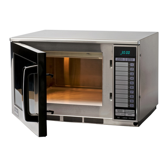
Page 5: Appearance View
DISPLAY AND INDICATORS CATORS for R-23AM HIGH 1 2 3 DOUBLE FILTER for R-22AT and R-24AT Check indicators after Check indicators after the oven the oven starts to con- MEDIUM starts to confirm the oven is oper- firm the oven is operat-... -
Page 6: Operation Sequence
IDLE CONDITION 4. When the cooking time is up, a signal tone is heard and the relays RY3+RY4 (for R-22AT/24AT)/ RY2+RY3 When the door is opened, the contacts of the 1st. latch (for R-23AM) go back to their home position. The switch SW1, 2nd. - Page 7 R - 2 2 A T R-23AM R - 2 4 A T power, the line voltage is supplied to the high voltage TWO MAGNETRON OPERATION SYSTEM transformers T1+T2 intermittently within a 48 second time Two magnetrons MG1+MG2 are equipped in order to get base through the contacts of the relays RY3+RY4.
-
Page 8: Function Of Important Components
R - 2 2 A T R-23AM R - 2 4 A T FUNCTION OF IMPORTANT COMPONENTS DOOR OPEN MECHANISM CAUTION:BEFORE REPLACING A BLOWN FUSE F2 F6.3A TEST THE 1ST LATCH SWITCH SW1, 1. The door release lever is pulled. MONITOR SWITCH SW4 AND MONITOR 2. -
Page 9: Troubleshooting Guide
R - 2 2 A T R-23AM R - 2 4 A T cavity, the oven temperature fuse will open at 120˚C, MAGNETRON THERMISTOR causing the oven to shut down. The defective temperature The thermistor is a negative temperature coefficient type. fuse must be replaced with new rated one. - Page 10 R - 2 2 A T R-23AM R - 2 4 A T...
-
Page 11: Test Procedure
Initial temperature (T1) ...... 10±1°C Heating time ..28 sec. [R-22AT] / 22sec. [R-23AM/24AT] Mass of container (mc) ..330 g P = 150 x ∆T [R-22AT] / P = 190 x ∆T [R-23AM, R-24AT] T2 ..Final Temperature Measuring condition: 1. - Page 12 Measured output power The equation is “P = 150 x ∆T” [for R-22AT] ......P = 150 x 10°C = 1500 Watts The equation is “P = 190 x ∆T” [for R-23AM/24AT] ....P = 190 x 10°C = 1900 Watts ±...
- Page 13 HV circuitry. Using an ohmmeter, set on a low range, it is possible to check the continuity of all three windings. The following readings should be obtained:- R-22AT R-23AM, R-24AT approximately 1.8 Ω...
- Page 14 R - 2 2 A T R-23AM R - 2 4 A T TEST PROCEDURES PROCEDURE LETTER COMPONENT TEST Table: Terminal Connection of Switch COM; Common terminal, Plunger Operation COM to NO COM to NC Normally open terminal Released Open circuit Short circuit Normally close terminal Depressed...
- Page 15 R - 2 2 A T R-23AM R - 2 4 A T TEST PROCEDURES PROCEDURE LETTER COMPONENT TEST MONITOR RESISTOR R1 TEST CARRY OUT 3D CHECKS. Disconnect the leads from the monitor resistor R1. Using an ohmmeter and set on a low range. Check between the terminals of the monitor resistor R1.
- Page 16 CAUTION: Only replace high voltage fuse with the correct value replacement. TOUCH CONTROL PANEL ASSEMBLY TEST FOR R-24AT / R-22AT The touch control panel consists of circuits including semiconductors such as LSI, IC, etc. Therefore, unlike conventional microwave ovens, proper maintenance cannot be performed with only a voltmeter and ohmmeter.
- Page 17 Remove the outer case and check voltage between Pin Nos. 5 and 7 of the connector (A) on the control unit with an A.C. voltmeter. The meter should indicate 230~240 volts, if not check control unit circuity. RY1, RY3 and RY4 Relay Test For R-24AT / R-22AT These relays are operated by D.C. voltage.
- Page 18 Check and repair. Only pattern at "a" is broken. *Insert jumper wire J24 and solder for R-24AT / R-22AT. *Insert jumper wire J9 and solder for R-23AM. (CARRY OUT 3D CHECKS BEFORE REPAIR) Pattern at "a" and "b" are broken.
-
Page 19: Touch Control Panel Assembly
R - 2 2 A T R-23AM R - 2 4 A T TOUCH CONTROL PANEL ASSEMBLY FOR R-24AT / R-22AT OUTLINE OF TOUCH CONTROL PANEL The touch control section consists of the following units as This AC voltage is the input to the IN3 and IN5 ports of shown in the touch control panel circuit. - Page 20 This is a circuit for driving IC1 to detect door opening/ LSI. closing. DESCRIPTION OF LSI FOR R-24AT / R-22AT LSI(IZA646DR) The I/O signal of the LSI(IZA646DR) is detailed in the following table. Pin No.
- Page 21 R - 2 2 A T R-23AM R - 2 4 A T Pin No. Signal Description Temperature measurement input: MAGNETRON THERMISTOR AND OVEN THERMISTOR (2). By inputting DC voltage corresponding to the temperature detected by the thermis- tor, this input is converted into temperature by the A/D converter built into the LSI. Temperature measurement input: OVEN THERMISTOR (1).
- Page 22 R - 2 2 A T R-23AM R - 2 4 A T Pin No. Signal Description Terminal not used. CNVSS Connected to Vc.(-5V) RESET Auto clear terminal. Signal is input to reset the LSI to the initial state when power is supplied. Temporarily set to "L"...
- Page 23 R - 2 2 A T R-23AM R - 2 4 A T Pin No. Signal Description Segment data signal. Signal similar to P17. Key strobe signal. Signal applied to touch-key section. A pulse signal is input to R0 - R3 terminal while one of G-7 line keys on key matrix is touched.
- Page 24 R - 2 2 A T R-23AM R - 2 4 A T Pin No. Signal Description AN7-AN6 Terminal to switch the specification. Connected to GND. A/D input for troubleshooting Magnetron 1. A/D input for troubleshooting Magnetron 2. Temperature measurement input: OVEN THERMISTOR (1). By inputting DC voltage corresponding to the temperature detected by the thermis- tor, this input is converted into temperature by the A/D converter built into the LSI.
- Page 25 R - 2 2 A T R-23AM R - 2 4 A T Pin No. Signal Description 28-29 P71-P70 Terminal not used. Internal clock oscillation frequency setting input. The internal clock frequency is set by inserting the ceramic filter oscillation circuit with respect to XOUT terminal.
- Page 26 R-23AM R - 2 4 A T 2-2 Memory IC (IC2) FOR R-24AT / R-22AT AT24C04 is a 4K-bit, serial memory, enabling CMOS to be erased/written electrically. This memory is constructed with 512 registers x 8bits, enabling individual access, read and write operations to be performed. Details of input/output signal for IC2 are as shown in the following diagram.
- Page 27 R - 2 2 A T R-23AM R - 2 4 A T SERVICING 1. Precautions for Handling Electronic Components control panel with a jumper, which brings about an This unit uses CMOS LSI in the integral part of the operational state that is equivalent to the oven door being circuits.
- Page 28 PROCEDURE FOR CHECKING/CLEARING SERV- PROCEDURE FOR ENTERING TO IC-2 FOR R- ICE COUNTS OF MICROWAVE OVEN FOR R- 24AT / R-22AT 24AT / R-22AT When the control unit or IC-2 is exchanged, re-enter the constans of EXPRESS DEFROST, the memory information The following procedure enables the servicer to obtain the and the EEPROM data, referring to the following procedures.
- Page 29 100% OTHER CHECKING AND CLEARING PROCE- 11-20 0 sec. DURE FOR R-24AT / R-22AT 3) How to enter the EEPROM pad. 1) To check the contents of defrost. Enter the EEPROM data into the memory pads, 3, 4,6, 8, 9, 11, 12, 13, 14, 15 and 20, referring to following example "...
-
Page 30: Component Replacement And Adjustment Procedure
WARNING FOR WIRING To prevent an electric shock, take the following and Oven cavity. precautions. 3) Sharp edge: 1. Before wiring, Bottom plate, Oven cavity, Waveguide flange, 1) Disconnect the power supply cord. Chassis support and other metallic plate. - Page 31 R - 2 2 A T R-23AM R - 2 4 A T 4. Remove the wire lead(s) of high voltage transformer(s) 8. Disconnect the main wire harness from high voltage from the wire holder. transformer(s). 5. Pull out the wire lead(s) of high voltage transformer(s) 9.
- Page 32 1. CARRY OUT 3D CHECKS. 3. Where the portions have been snipped off bend the 2. Disconnect the wire leads from the stirrer motor (up- portions flat. No sharp edge must be evident after per). removal of the stirrer motor cover.
- Page 33 COVER THE TIP OF SCREWDRIVER WITH TAPE. varistor works, because it will explode and the (3) If the relay (RY-4 for R-22AT/24AT ; RY-3 for R-23AM) wire leads near by the varistor will be damaged. is hit, re-solder the Relay (RY-4) prior to reinstalling the Touch Control Panel.
- Page 34 R - 2 2 A T R-23AM R - 2 4 A T for R-22AT and R-24AT 2. When inserting key cable to main body set, CONTROL UNIT AND CONTROL PANEL FRAME ensure them free from caught-in trouble. In addition, when installing the control panel as-...
- Page 35 R - 2 2 A T R-23AM R - 2 4 A T 1. Loosen the two (2) screws holding the latch hook. 3. Re-install outer case and check for microwave leakage 2. With the door closed, adjust the latch hook by moving around the door with an approved microwave survey it back and forward, or up and down.
-
Page 36: Service Information
MOVAL" of "DOOR REPLACEMENT AND ADJUST- SERVICE INFORMATION IMPORTANT: When the magnetron MG1 and/or MG2 is replacing, the relays (RY3 and RY4 for R-22AT/24AT; RY2 and RY3 for R-23AM) on control unit must be replaced at the same time. Because if the... -
Page 37: Microwave Measurement
R - 2 2 A T R-23AM R - 2 4 A T MICROWAVE MEASUREMENT After any repair, the microwave oven must be checked for Before commencing the test, check that the leakage detector is functioning and adjusted according to the microwave leakage to ensure continued safe operation. - Page 38 F4: FUSE M8A TEMP. FUSE 150 °C TF2: MAGNETRON (MG2) C1: H.V. CAPACITOR TEMP. FUSE 150°C F3: FUSE M8A H.V. FUSE 0.6 A/ 5 kV (R-22AT) 0.75 A/ 5 kV R-24AT R-23AM CONTROL UNIT C2: H.V. CAPACITOR SW5: STOP H.V.
- Page 39 R - 2 2 A T R-23AM R - 2 4 A T SCHEMATIC NOTE: CONDITION OF OVEN 1. DOOR CLOSED. 2. MANUAL/ REPEAT KEY TOUCHED [R-22AT/24AT]. 3. COOKING TIME PROGREMMED. NOTE: Indicates components with potential above 250 V. 4. START PAD TOUCHED. NOISE FILTER...
- Page 40 R - 2 2 A T R-23AM R - 2 4 A T...
- Page 41 R - 2 2 A T R-23AM R - 2 4 A T...
- Page 42 R - 2 2 A T R-23AM R - 2 4 A T...
- Page 43 R - 2 2 A T R-23AM R - 2 4 A T...
-
Page 44: Printed Wiring Board
(D200) (D74 ,R50) (R76) (R77 ,J31) (D50) (R86) DOOR (J11) (C11) (J15) (J14,C10) (R2) TAB1 TAB2 (J17) (J16) (J18, R82) (J19) (J21) (J20, R81) (RY2) (J24) (F1) (J26) (R7, J28) (R8) Figure S-5. Printed Wiring Board For R-24AT / R-22AT... - Page 45 R - 2 2 A T R-23AM R - 2 4 A T (R62) (Q60) (J10) (R61,J13) (D60, R65) (R60) (Q24) DOOR (R22,J22) (F1) (J7) (J9) Figure S-6. Printed Wiring Board For R-23AM...
-
Page 46: Parts List
1-15 QFS-TA014WRE0 Temperature fuse 150˚C (MG.) 1-16 QFS-TA015WRE0 Temperature fuse 120˚C (OVEN, BM.) 1-17 RTRN-A599WRE0 High voltage transformer [R-23AM/R-24AT] 1-17 RTRN-A600WRE0 High voltage transformer [R-22AT] 1-18 QSW-MA085WRE0 Stop switch 1-19 QSW-MA086WRE0 Monitor switch 1-20 QSW-MA095WRE0 1st. latch switch 1-21 QSW-MA095WRE0 2nd. - Page 47 Screw : 4mm x 20mm 5-21 PCUSUA523WRP0 Door lever cushion 5-22 PSPA-A102WRE0 Door case spacer MISCELLANEOUS 6- 1 TINSEA821WRR0 Operation manual [R-22AT, R-24AT] 6- 1 TINSEA822WRR0 Operation manual [R-23AM] 6- 2 TLABHA029WRR0 Menu sticker [R-22AT, R-24AT] 6- 3 FW-VZB769WRE0 Switch harness...
- Page 48 4. DESCRIPTION PACKING AND ACCESSORIES TOP PAD ASSEMBLY FPADBA313WRK0 DOOR PROTECTION SHEET SPADPA552WRE0 WRAP COVER BOTTOM PAD ASSEMBLY FPADBA314WRK0 DOOR PAD SPADF0341WRE0 TRAY SUPPORT SPADPA551WRE0 6-1 INSTRUCTION MANUAL PACKING CASE SPAKCD317WRE0 [R-24AT] SPAKCD320WRE0 [R-23AM] SPAKCD321WRE0 [R-22AT] * Not replaceable items.
- Page 49 R - 2 2 A T R-23AM R - 2 4 A T OVEN AND CABINET PARTS 7-26 7-29 4-20 7-18 6-11 4-23 6-10 2-5-1 7-25 4-33 7-16 7-31 7-18 2-5-2 7-26 4-43 4-30 7-18 7-22 7-33 7-13 7-32 7-22 7-16 7-22 4-39...
- Page 50 R - 2 2 A T R-23AM R - 2 4 A T DOOR PARTS 5-22 5-10 5-11 5-14 5-20 5-12 5-15 5-18 5-13 5-16 5-11 5-17 5-13 5-21 5-19 MISCELLANEOUS Actual wire harness may be different from illustration. 6-14 6-16...
- Page 51 R - 2 2 A T R-23AM R - 2 4 A T CONTROL PANEL PARTS FOR R-24AT / R-22AT REF. NO. PART NO. DESCRIPTION Q'TY CODE 3- 1 DPWBFB998WRU0 Control unit [R-24AT] 3- 1 DPWBFC005WRU0 Control unit [R-22AT] 3- 1A...
- Page 52 To have your order filled prompty and correctly, please furnish the following information. 1. MODEL NUMBER 2. REF. NO. 3. PART NO. 4. DESCRIPTION CONTROL PANEL PARTS R-22AT, R-24AT 3 - 2 3-2-3 3 - 1 6 - 9 3 - 5...
- Page 53 R - 2 2 A T R-23AM R - 2 4 A T CONTROL PANEL PARTS FOR R-23AM REF. NO. PART NO. DESCRIPTION Q'TY CODE 3- 1 DPWBFC003WRU0 Control unit 3- 1A QCNCMA308DRE0 4-pin connector (A) 3- 1B QCNCMA312DRE0 3-pin connector (B) 3- 1C QCNCMA381DRE0 5-pin connector (E)
- Page 54 R - 2 2 A T R-23AM R - 2 4 A T REF. NO. PART NO. DESCRIPTION Q'TY CODE 3- 2-1 GMADIA067WRF0 Display window 3- 2-2 HDECAA206WRP0 Decorative metal fittings 3- 2-3 HPNLCB155WRF0 Control panel 3- 2-4 PCUSUA451WRP0 Cushion 3- 3 LANGTA243WRW0 Control panel mounting angle...
- Page 55 R - 2 2 A T R-23AM R - 2 4 A T CONTROL PANEL PARTS R-23AM 3-2-4 3-12 3-19 3-2-3 3-2-1 3-20 3-2-2 3-18 3-16 3-17 3-23 3-21 3-22 3-15 3-13 3-10 3-14 3-11...
- Page 56 R - 2 2 A T R-23AM R - 2 4 A T '99SHARP CORP. (11S0.520E) Printed in Germany.
Need help?
Do you have a question about the R-22AT and is the answer not in the manual?
Questions and answers