Table of Contents
Advertisement
21 00 W/ R- 25
AM
CAUTION, MICROWAVE RADIATION ....................................................................... INSIDE FRONT COVER
WARNING .......................................................................................................................................................... 1
SERVICING ...................................................................................................................................................... 2
PRODUCT SPECIFICATIONS ......................................................................................................................... 5
GENERAL INFORMATION ................................................................................................................................ 5
APPEARANCE VIEW ....................................................................................................................................... 6
OPERATION SEQUENCE ................................................................................................................................ 7
FUNCTION OF IMPORTANT COMPONENTS ................................................................................................ 9
TROUBLESHOOTING GUIDE ........................................................................................................................ 10
TEST PROCEDURE ........................................................................................................................................ 12
TOUCH CONTROL PANEL ASSEMBLY ........................................................................................................ 18
COMPONENT REPLACEMENT AND ADJUSTMENT PROCEDURE ........................................................... 25
MICROWAVE MEASUREMENT .................................................................................................................... 32
TEST DATA AT A GLANCE ........................................................................................................................... 33
WIRING DIAGRAM ......................................................................................................................................... 34
PICTORIAL DIAGRAM ................................................................................................................................... 36
CONTROL PANEL CIRCUIT ........................................................................................................................... 37
PRINTED WIRING BOARD ............................................................................................................................. 38
PARTS LIST ................................................................................................................................................... 39
SERVICE MANUAL
MODEL
In interests of user-safety the oven should be restored to its
original condition and only parts identical to those specified
should be used.
TABLE OF CONTENTS
SHARP CORPORATION
COMMERCIAL
MICROWAVE OVEN
R-25AM
R-25AM
S0315R25AMH//
Page
Advertisement
Table of Contents

Subscribe to Our Youtube Channel
Related Manuals for Sharp R-25AM


Summary of Contents for Sharp R-25AM
-
Page 1: Table Of Contents
R-25AM SERVICE MANUAL S0315R25AMH// COMMERCIAL MICROWAVE OVEN R-25AM MODEL 21 00 W/ R- 25 In interests of user-safety the oven should be restored to its original condition and only parts identical to those specified should be used. TABLE OF CONTENTS Page CAUTION, MICROWAVE RADIATION ............... -
Page 2: Caution Microwave Radiation
R-25AM CAUTION MICROWAVE RADIATION Personnel should not be exposed to the microwave energy which may radiate from the magnetron or other microwave generating devices if it is improperly used or connected. All input and output microwave connections, waveguides, flanges and gaskets must be secured. -
Page 3: Warning
COMMERCIAL MICROWAVE OVEN R-25AM GENERAL INFORMATION GENERAL IMPORTANT INFORMATION This Manual has been prepared to provide Sharp Corp. Service engineers with Operation and Service Information. APPEARANCE VIEW It is recommended that service engineers carefully study the entire text of this manual, so they will be qualified to render satisfactory customer service. -
Page 4: Servicing
Sharp beveelt ten sterkste aan dat, voor zover mogelijk, defecten worden opgespoord wanneer de stekker uit het Wanneer alle reparaties zijn uitgevoerd en de oven weer in stopcontact is gehaald. - Page 5 är kallt utför Du 3 steg kontroller och kontrollerar anslutningarna till varje enskild komponent på nytt. Sharp rekommenderar att felsökning sker med strömmen fränkopplad. Ibland kan det var nödvändigt att koppla på När all service är klar och ugnen ihopskruvad skall ugnens strömmen efter det att höljet avlägsnats, utför da 3 Steg...
- Page 6 Sharp raccomanda, nei limiti del possibile, che la ricerca dei guasti avvenga in assenza di alimentazione elettrica. In alcuni casi tuttavia, può essere necessario alimentare Dopo aver portato a termine le operazioni di manutenzione l'apparecchio dopo aver rimosso la scatola esterna.
-
Page 7: Product Specifications
R-25AM PRODUCT DESCRIPTION SPECIFICATION ITEM DESCRIPTION Power Requirements 230 Volts 50 Hertz Single phase, 3 wire earthed Power Comsumption 3.15 kW Approx. 15 A Power Output 2100 W nominal of RF microwave energy (measured by method of IEC 60705) Operating frequency 2450 MHz... -
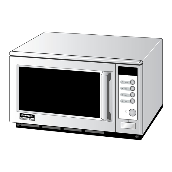
Page 8: Appearance View
R-25AM APPEARANCE VIEW OVEN 1. Control panel 2. Hole for safety door latches 3. Ceramic floor 4. Splash cover 5. Oven light 6. Air intake filter 7. Air intake openings 8. Oven cavity 9. Door seals and sealing surfaces 10. Door hinges 11. -
Page 9: Operation Sequence
R-25AM OPERATION SEQUENCE Closing the door activates all door interlock switches 4. When the cooking time is up, a signal tone is heard and (interlock switches and stop switch). the relays RY3+RY4 go back to their home position. The circuits to the high voltage transformers T1+T2. - Page 10 R-25AM TWO MAGNETRON OPERATION SYSTEM Two magnetrons MG1+MG2 are equipped in order to get higher microwave power output. The primary windings of the high voltage transformers T1+T2 are connected so that each magnetron can be oscillated alternatively ac- cording to the frequency of the power supply. Refer to the Figure B-1 and B-2.
-
Page 11: Function Of Important Components
R-25AM FUNCTION OF IMPORTANT COMPONENTS DOOR OPEN MECHANISM CAUTION:BEFORE REPLACING A BLOWN FUSE F1 F10A (OR F2 F10A) TEST THE INTERLOCK 1. The door release lever is pulled. SWITCH SW1 (OR SW2) AND MONITOR 2. The upper latch head is lifted up by the linked door SWITCHE SW3 (OR SW4) FOR PROPER release lever. -
Page 12: Troubleshooting Guide
R-25AM catching fire. BLOWER MOTOR BM If the thermistor is open, the control panel will display The blower motor BM drives a blade which draws external "EE6" and the oven will stop. cool air into the oven. This cool air is directed through the... - Page 13 R-25AM EEP ROM I-2 SWITCH UNIT TOUCH CONTROL TRANSFORMER T3 Due to programme lock Over the max. cooking time No power at wall outlet HOME FUSE or BREAKER Mis adjustment of switches FUSE 2.5A RELAY RY-4 RELAY RY-3 RELAY RY-1...
-
Page 14: Test Procedure
R-25AM TEST PROCEDURES PROCEDURE LETTER COMPONENT TEST MAGNETRON TEST NEVER TOUCH ANY PART IN THE CIRCUIT WITH YOUR HAND OR AN INSULATED TOOL WHILE THE OVEN IS IN OPERATION. CARRY OUT 3D CHECKS. Isolate the magnetron from high voltage circuit by removing all leads connected to filament terminal. - Page 15 R-25AM TEST PROCEDURES PROCEDURE LETTER COMPONENT TEST Room temperature ....................T0 = 21°C Initial temperature ....................T1 = 11°C Temperature after (20 + 3) = 23 sec ..............T2 = 21°C Temperature difference Cold-Warm..............∆T1 = 10˚C Measured output power The equation is “P = 210 x ∆T”...
- Page 16 R-25AM TEST PROCEDURES PROCEDURE LETTER COMPONENT TEST HIGH VOLTAGE CAPACITOR TEST CARRY OUT 3D CHECKS. A. Isolate the high voltage capacitor from the circuit. B. Continuity check must be carried out with measuring instrument which is set to the highest resistance range.
- Page 17 R-25AM TEST PROCEDURES PROCEDURE LETTER COMPONENT TEST Open Close Display or temperature temperature Condition Check point Magnetron MG1 Failure: Magnetron tem- perature fuse (Up- Test magnetron MG1 and Blower motor. per) TF1 Non resetable Magnetron MG1, MG2 Failure: Test magnetron MG1, 150˚C...
- Page 18 R-25AM TEST PROCEDURES PROCEDURE LETTER COMPONENT TEST TOUCH CONTROL PANEL ASSEMBLY TEST The touch control panel consists of circuits including semiconductors such as LSI etc. Therefore, unlike conventional microwave ovens, proper maintenance cannot be performed with only a voltmeter and ohmmeter. In this service manual, the touch control panel assembly is divided into three units, Control Unit, Switch Unit and Encoder Unit troubleshooting by unit replacement is described according to the symptoms indicated.
- Page 19 R-25AM TEST PROCEDURES PROCEDURE LETTER COMPONENT TEST RY1, RY3 and RY4 Relay Test These relays are operated by D.C. voltage. Check voltage at the relay coil with a D.C. voltmeter during the microwave cooking operation. DC. voltage indicated ......Defective relay.
-
Page 20: Touch Control Panel Assembly
R-25AM TOUCH CONTROL PANEL ASSEMBLY OUTLINE OF TOUCH CONTROL PANEL The touch control section consists of the following units as 2. Switch Unit shown in the touch control panel circuit. The switch unit is composed of a matrix circuit in which... - Page 21 R-25AM DESCRIPTION OF LSI LSI(IXA222DR) The I/O signal of the LSI(IXA222DR) is detailed in the following table. Pin No. Signal Description Power source voltage: GND. VC voltage of power source circuit input. Connected to GND. Anode (segment) of Fluorescent Display light-up voltage: -35V.
- Page 22 R-25AM Pin No. Signal Description 20-21 P46-P45 Terminal not used. Oven lamp, Blower motor and Antenna motor driving signal (Square Waveform : 50Hz). During cooking To turn on and off the shut-off relay (RY1). The Square waveform voltage is delivered...
- Page 23 R-25AM Pin No. Signal Description 41-46 P17-P12 Segment data signal. Signal similar to P23.. 47-48 P11-P10 Digit selection signal. The relation between digit signal and digit ß(50Hz) are as follows: Digit signal Digit -31(V) P11 ....1st. P10 ....2nd.
- Page 24 R-25AM 2-2 Memory IC (I-2) CAT24WC16P1 is a 16K-bit, serial memory, enabling CMOS to be erased/written electrically. This memory is constructed with 512 registers x 8bits, enabling individual access, read and write operations to be performed. Details of input/output signal for IC2 are as shown in the following diagram.
- Page 25 R-25AM SERVICING 1. Precautions for Handling Electronic Components both ends of the door sensing switch (on PWB) of the touch control panel with a jumper, which brings about This unit uses CMOS LSI in the integral part of the circuits. When handling these parts, the following an operational state that is equivalent to the oven door precautions should be strictly followed.
- Page 26 R-25AM PRECAUTIONS FOR USING LEAD-FREE SOLDER 1. Employing lead-free solder The "Main PWB" of this model employs lead-free solder. This is indicated by the "LF" symbol printed on the PWB and in the service manual. The suffix letter indicates the alloy type of the solder.
-
Page 27: Component Replacement And Adjustment Procedure
WARNING FOR WIRING To prevent an electric shock, take the following and Oven cavity. precautions. 3) Sharp edge: 1. Before wiring, Bottom plate, Oven cavity, Waveguide flange, 1) Disconnect the power supply cord. Chassis support and other metallic plate. - Page 28 R-25AM 5. Pull out the wire lead(s) of high voltage transformer(s) 8. Disconnect the main wire harness from high voltage from the tube. transformer(s). 6. Disconnect wire lead(s) of high voltage transformer(s) 9. Remove two (2) screws holding each power trans- from high voltage capacitor(s).
- Page 29 1. CARRY OUT 3D CHECKS. 3. Where the portions have been snipped off bend the 2. Disconnect the wire leads from the stirrer motor (up- portions flat. No sharp edge must be evident after per). removal of the stirrer motor cover.
- Page 30 R-25AM Installation 2. Close covers of the terminal insulator, as shown 1. Insert the receptacle into terminal insulator. illustlated below. COVERS Flat type Terminal screw driver RECEPTACLE insulator CONTROL PANEL ASSEMBLY AND CONTROL UNIT REMOVAL Replacement of individual component is as follows:...
- Page 31 R-25AM Re-install Power supply cord 1. Insert the power supply cord into the cord bushing. 2. Connect the brown and blue wires of power supply cord Cord bushing Screw into the terminals of noise filter, referring to pictorial diagram. Green/Yellow wire 3.
- Page 32 R-25AM 3. Remove door assembly with upper and lower oven 2. Deviation of the door alignment from horizontal line of hinges by pulling it forward. cavity face plate is to be less than 1.0mm. 4. Release upper and lower oven hinges from door as- 3.
-
Page 33: Service Information
R-25AM 5. Remove the door handle from door panel. to "REMOVAL" of "DOOR REPLACEMENT AND AD- 6. Now, door handle is free. JUSTMENT". 2. Remove choke cover from door panel, referring to UPPER AND LOWER LATCH HEADS REMOVAL "CHOKE COVER REMOVAL". -
Page 34: Microwave Measurement
R-25AM MICROWAVE MEASUREMENT Recommended instruments are: After adjustment of door latch switches, monitor switch and door are completed individually or collectively, the NARDA 8100 following leakage test must be performed with a survey NARDA 8200 instrument and it must be confirmed that the result meets... -
Page 35: Test Data At A Glance
R-25AM TEST DATA AT A GLANCE Parts Symbol Value / Data Fuse F10A Fuse F10A Weak point A017 High voltage fuse F4, F5 0.75A 5kV Temperature fuse (Upper Mag.) 150˚C Temperature fuse (Lower Mag.) 150˚C Temperature fuse(Exhaust) 120˚C Magnetron thermistor (Upper) Approx. -
Page 36: Wiring Diagram
R-25AM SCHEMATIC NOTE: CONDITION OF OVEN 1. POWER SUPPLY CONNECTED AND/OR 1MINUTE AFTER DOOR CLOSED OR COOK OFF. APPEAR ON DISPLAY. NOTE: Indicates components with potential above 250 V. TF1: TEMP. FUSE 150¡C (Upper Mag.) NOISE FILTER C1: H.V. CAPACITOR TF1: 1.07 F/ AC2300V... - Page 37 R-25AM SCHEMATIC NOTE: CONDITION OF OVEN NOTE: Indicates components with potential above 250 V. 1. DOOR CLOSED. 2. MANUAL/ REPEAT KEY TOUCHED. 3. COOKING TIME PROGREMMED. 4. START PAD TOUCHED. TF1: TEMP. FUSE 150¡C (Upper Mag.) NOISE FILTER C1: H.V. CAPACITOR TF1: 1.07 F/ AC2300V...
-
Page 38: Pictorial Diagram
R-25AM... -
Page 39: Control Panel Circuit
R-25AM... -
Page 40: Printed Wiring Board
R-25AM BLACK 2.5A FUSE Figure S-3. Printed Wiring Board... -
Page 41: Parts List
R-25AM PARTS LIST ∆ Note: The parts marked " " may cause undue microwave exposure. The parts marked "*" are used in voltage more than 250V. REF. NO. PART NO. DESCRIPTION Q'TY CODE ELECTORIC PARTS FMOTEA482WRKZ Blower motor C1, C2... - Page 42 R-25AM REF. NO. PART NO. DESCRIPTION Q'TY CODE VHD1SS133//-2 Diode (1SS133) VHD1SS133//-2 Diode (1SS133) D83-84 VHD1SS133//-2 Diode (1SS133) QFS-IA001KKZZ Fuse 2.5A I- 1 RH-IXA222DRZZ I- 2 VHICAT24W16-1 EEPROM VSKRA101M//-3 Transistor (KRA101M) VHIKIA79L05-3 Transistor (KIA79L05P) VS2SB953-PQ-4 Transistor (2SB953) VSKRA101M//-3 Transistor (KRA101M)
- Page 43 R-25AM ∆ Note: The parts marked " " may cause undue microwave exposure. The parts marked "*" are used in voltage more than 250V. REF. NO. PART NO. DESCRIPTION Q'TY CODE 4- 7 MLEVPA155WRF0 Switch lever C 4- 8 MSPRCA075WRE0...
- Page 44 R-25AM REF. NO. PART NO. DESCRIPTION Q'TY CODE SCRE,NUTS AND WASHERS 7- 1 LX-BZA131WREZ Special screw 7- 2 LX-BZA138WREZ Special screw 7- 3 XHTSD40P08RV0 Screw : 4mm x 8mm 7- 4 XONSC40P10000 Screw : 4mm x 10mm 7- 5 XOTSC40P12000...
- Page 45 R-25AM OVEN AND CABINET PARTS 7-21 4-20 4-23 2-4-1 7-16 4-30 4-33 2-4-2 4-43 7-10 7-19 7-18 4-26 7-17 4-39 7-25 4-25 4-27 4-38 7-14 4-28 4-13 4-29 4-21 7-14 4-12 7-13 7-12 7-15 4-18 4-40 4-37 4-24 7-14 4-40...
- Page 46 R-25AM CONTROL PANEL PARTS 3-2-4 3-12 3-14 3-17 3-2-3 3-2-1 3-18 3-2-2 DOOR PARTS 3-15 3-16 3-13 3-10 5-22 3-11 5-10 5-14 5-23 5-12 5-15 5-18 5-13 5-16 5-17 MISCELLANEOUS 5-11 5-13 5-21 5-19 5-20 5-11 Actual wire harness may be different from illustration.
-
Page 47: Packing And Accessories
R-25AM PACKING AND ACCESSORIES TOP PAD ASSEMBLY FPADBA313WRK0 DOOR PROTECTION SHEET SPADPA552WRE0 WRAP COVER SSAKH0111WRE0 BOTTOM PAD ASSEMBLY FPADBA314WRK0 DOOR PAD SPADF0341WRE0 TRAY SUPPORT SPADPA551WRE0 6-1 OPERATION MANUAL PACKING CASE SPAKCE009WREZ * Not replaceable items. - Page 48 R-25AM COPYRIGHT © 2003 BY SHARP CORPORATION ALL RIGHTS RESERVED. No part of this publication may be reproduced, stored in retrieval systems, or transmitted in any form or by any means, electronic, mechanical, photocopying, recording, or otherwise, without prior written permission of the publisher.
Need help?
Do you have a question about the R-25AM and is the answer not in the manual?
Questions and answers