Sharp R-24AT Service Manual
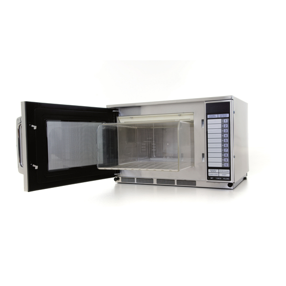
Commercial microwave oven
Hide thumbs
Also See for R-24AT:
- Operation manual (32 pages) ,
- Service manual (56 pages) ,
- Operation manual (33 pages)
Table of Contents
Advertisement
19 00 W/ R- 24
AT
R-24AT
Because many parts have been changed to improve quality of these models from May 2005 production.
And the changed parts are not interchangeable. Please use this service manual for above products.
For old products, please use old service manual (No.SX910R24ATK//) and technical reports.
SERVICING ................................................................................................................. INSIDE FRONT COVER
CAUTION, MICROWAVE RADIATION ............................................................................................................ 1
WARNING .......................................................................................................................................................... 1
PRODUCT SPECIFICATIONS ......................................................................................................................... 2
GENERAL INFORMATION ................................................................................................................................ 2
APPEARANCE VIEW ....................................................................................................................................... 3
OPERATION SEQUENCE ................................................................................................................................ 4
FUNCTION OF IMPORTANT COMPONENTS ................................................................................................ 6
TROUBLESHOOTING GUIDE .......................................................................................................................... 7
TEST PROCEDURE .......................................................................................................................................... 8
TOUCH CONTROL PANEL ASSEMBLY ........................................................................................................ 16
COMPONENT REPLACEMENT AND ADJUSTMENT PROCEDURE ........................................................... 24
WIRING DIAGRAM ......................................................................................................................................... 32
PICTORIAL DIAGRAM ................................................................................................................................... 34
CONTROL PANEL CIRCUIT ........................................................................................................................... 35
PRINTED WIRING BOARD ............................................................................................................................. 36
PARTS LIST ................................................................................................................................................... 37
SERVICE MANUAL
DOU BLE
EXP RES S
QUA NTIT Y
DEF ROS T
1
11
2
12
3
13
MODELS
14
4
15
5
6
16
7
17
18
8
19
9
20
0
MANU AL/
REHE AT
STOP / CLEA
R
POW ER LEVE
L
STAR T
SET
CHEC K
VOLU ME
In interests of user-safety the oven should be restored to its
original condition and only parts identical to those specified
should be used.
This revised service manual is applied to
R-22AT from serial No. 050505509 and
R-24AT from serial No. 050508658.
TABLE OF CONTENTS
SHARP CORPORATION
COMMERCIAL
MICROWAVE OVEN
R-22AT
R-24AT
R-22AT
R-24AT
SY520R24ATK//
Page
Advertisement
Table of Contents

Related Manuals for Sharp R-24AT


Summary of Contents for Sharp R-24AT
-
Page 1: Table Of Contents
This revised service manual is applied to R-22AT from serial No. 050505509 and R-24AT from serial No. 050508658. Because many parts have been changed to improve quality of these models from May 2005 production. And the changed parts are not interchangeable. Please use this service manual for above products. -
Page 2: Servicing
3D checks and re-examine the connections to the screwdriver. component being tested. Sharp recommend that wherever possible fault-finding When all service work is completed and the oven is fully is carried out with the supply disconnected. It may, in... -
Page 3: Caution Microwave Radiation
APPEARANCE VIEW R-22AT/ R-24AT GENERAL IMPORTANT INFORMATION OPERATING SEQUENCE This Manual has been prepared to provide Sharp Corp. Service engineers with Operation and Service Information. It is recommended that service engineers carefully study the FUNCTION OF IMPORTANT entire text of this manual, so they will be qualified to render COMPONENTS satisfactory customer service. -
Page 4: General Information
50 Hertz Single phase, 3 wire earthed Power Comsumption 2.4 kW Approx. 11 A [R-22AT] / 2.9 kW Approx. 13 A [R-24AT] Power Output 1500 W [R-22AT]/ 1900 W [R-24AT] nominal of RF microwave energy (measured by method of IEC 60705) Operating frequency 2450 MHz... -
Page 5: Appearance View
R-22AT R-24AT APPEARANCE VIEW OVEN 1. Control panel 2. Hole for safety door latches 3. Ceramic floor 4. Splash cover 5. Oven light 6. Air intake filter 7. Air intake openings 8. Oven cavity 9. Door seals and sealing surfaces 10. -
Page 6: Operation Sequence
R-22AT R-24AT OPERATION SEQUENCE Closing the door activates all door interlock switches to negative voltage of approximately 4000 volts D.C.. (interlock switches and stop switch). 3. The 2450 MHz microwave energy produced in the magnetron generates a wave length of 12.24 cm. This... - Page 7 R-22AT R-24AT 48 sec. ON Number key 44sec. ON Number key 9 40 sec. ON Number key 8 36 sec. ON Number key 7 32 sec. ON Number key 6 26 sec. ON Number key 5 22 sec. ON Number key 4 16 sec.
-
Page 8: Function Of Important Components
R-22AT R-24AT FUNCTION OF IMPORTANT COMPONENTS DOOR OPEN MECHANISM 3. If the door is opened and the interlock switch SW1 (or SW2) contacts fail to open, the fuse F1 F10A (or F2 1. The door release lever is pulled. F10A) blows simultaneously with closing of the monitor 2. -
Page 9: Troubleshooting Guide
R-22AT R-24AT EXHAUST OVEN THERMISTOR TH3 BLOWER MOTOR BM The thermistor is a negative temperature coefficient type. The blower motor BM drives a blade which draws external The temperature in the exhaust duct is detected through cool air into the oven. This cool air is directed through the the resistance of the thermistor. - Page 10 R-22AT R-24AT EEP ROM I-2 KEY UNIT TOUCH CONTROL TRANSFORMER T3 Due to programme lock Over the max. cooking time No power at wall outlet HOME FUSE or BREAKER Mis adjustment of switches FUSE 2.5A RELAY RY-4 RELAY RY-3 RELAY RY-1...
-
Page 11: Test Procedure
Initial temperature (T1) ...... 10±1°C Heating time ....28 sec. [R-22AT] / 22sec. [R-24AT] Mass of container (mc) ..330 g P = 150 x ∆T [R-22AT] / P = 190 x ∆T [R-24AT] T2 ..Final Temperature Measuring condition: 1. - Page 12 Measured output power The equation is “P = 150 x ∆T” [for R-22AT] ......P = 150 x 10°C = 1500 Watts The equation is “P = 190 x ∆T” [for R-24AT] ......P = 190 x 10°C = 1900 Watts ±...
- Page 13 R-22AT R-24AT TEST PROCEDURES PROCEDURE LETTER COMPONENT TEST HIGH VOLTAGE TRANSFORMER TEST WARNING: High voltage and large currents are present at the secondary winding and filament winding of the high voltage transformer. It is very dangerous to work near this part when the oven is on. NEVER make any voltage measurements of the high-voltage circuits, including the magnetron filament.
- Page 14 R-22AT R-24AT TEST PROCEDURES PROCEDURE LETTER COMPONENT TEST Table: Terminal Connection of Switch COM; Common terminal, Plunger Operation COM to NO COM to NC Normally open terminal Released Open circuit Short circuit Normally close terminal Depressed Short circuit Open circuit If incorrect readings are obtained, make the necessary switch adjustment or replace the switch.
-
Page 15: Touch Control Panel Assembly
R-22AT R-24AT TEST PROCEDURES PROCEDURE LETTER COMPONENT TEST If the meter does not indicate above resistance, replace the thermistor. 3. CARRY OUT 4R CHECKS. MOTOR WINDING TEST CARRY OUT 3D CHECKS. Disconnect the leads from the motor. Using an ohmmeter, check the resistance between the two terminals. - Page 16 R-22AT R-24AT TEST PROCEDURES PROCEDURE LETTER COMPONENT TEST f) A certain group of indicators do not light up. g) The figure of all digits flicker. 2-3 Other possible problems caused by defective control unit. a) Buzzer does not sound or continues to sound.
- Page 17 R-22AT R-24AT TEST PROCEDURES PROCEDURE LETTER COMPONENT TEST STEPS OCCURRENCE CAUSE OR CORRECTION The rated AC voltage is not present at Check supply voltage and oven power cord. POWER terminal of CPU connector (CN-A). The rated AC voltage is present at primary Touch control transformer or secondary circuit defective.
-
Page 18: Touch Control Panel Assembly
R-22AT R-24AT TOUCH CONTROL PANEL ASSEMBLY OUTLINE OF TOUCH CONTROL PANEL The touch control section consists of the following units as 2. Key Unit shown in the touch control panel circuit. The key unit is composed of a matrix circuit in which... -
Page 19: Description Of Lsi
R-22AT R-24AT DESCRIPTION OF LSI LSI(IXA222DR) The I/O signal of the LSI(IXA222DR) is detailed in the following table. Pin No. Signal Description Power source voltage: GND. VC voltage of power source circuit input. Connected to GND. Anode (segment) of Fluorescent Display light-up voltage: -35V. - Page 20 R-22AT R-24AT Pin No. Signal Description Signal to sound buzzer. 0.12 sec This signal is to control the 2.5kHz continuous signal. 2.4 sec 1.2 sec 1.2 sec A: Switch touch sound. B: Guidance sound. C: Completion sound. 200 sec. 200 sec.
- Page 21 R-22AT R-24AT Pin No. Signal Description §(50Hz) -31(V) 41-46 P17-P12 Segment data signal. Signal similar to P23.. 47-48 P11-P10 Digit selection signal. §(50Hz) The relation between digit signal and digit are as follows: Digit signal Digit -31(V) P11 ....1st.
- Page 22 R-22AT R-24AT 2-2 Memory IC (I-2) CAT24WC16PI is a 4K-bit, serial memory, enabling CMOS to be erased/written electrically. This memory is constructed with 512 registers x 8bits, enabling individual access, read and write operations to be performed. Details of input/output signal for IC2 are as shown in the following diagram.
- Page 23 R-22AT R-24AT touch control panel with a jumper, which brings about 1) Soldering iron: 60W an operational state that is equivalent to the oven door (It is recommended to use a soldering iron with a being closed. As for the sensor-related controls of the grounding terminal.)
- Page 24 R-22AT R-24AT PROCEDURE FOR ENTERING TO I-2 When the control unit or I-2 is exchanged, re-enter the 2) How to enter the memory information constants of EXPRESS DEFROST, the memory information Example : Suppose cooking time 5 sec. and output power and the EEPROM data, referring to the following procedures.
- Page 25 R-22AT R-24AT 2) How to clear all counter(user and service) and total cooking time and used time of filter. PAD ORDER DISPLAY PHONE (Door close) • • "NUMBER" • DOUBLE "NUMBER" • DOUBLE QUANTITY CHECK "NUMBER" • DOUBLE SIGNAL "NUMBER" • DOUBLE •...
-
Page 26: Component Replacement And Adjustment Procedure
WARNING FOR WIRING To prevent an electric shock, take the following and Oven cavity. precautions. 3) Sharp edge: 1. Before wiring, Bottom plate, Oven cavity, Waveguide flange, 1) Disconnect the power supply cord. Chassis support and other metallic plate. - Page 27 R-22AT R-24AT 5. Pull out the wire lead(s) of high voltage transformer(s) 8. Disconnect the main wire harness from high voltage from the tube. transformer(s). 6. Disconnect wire lead(s) of high voltage transformer(s) 9. Remove two (2) screws holding each power trans- from high voltage capacitor(s).
- Page 28 1. CARRY OUT 3D CHECKS. 3. Where the portions have been snipped off bend the 2. Disconnect the wire leads from the stirrer motor (up- portions flat. No sharp edge must be evident after per). removal of the stirrer motor cover.
- Page 29 R-22AT R-24AT Installation 2. Close covers of the terminal insulator, as shown 1. Insert the receptacle into terminal insulator. illustlated below. COVERS Flat type Terminal screw driver RECEPTACLE insulator CONTROL PANEL ASSEMBLY AND CONTROL UNIT REMOVAL Replacement of individual component is as follows:...
-
Page 30: Microwave Measurement
R-22AT R-24AT 5. Remove the power supply cord. Power supply cord Re-install 1. Insert the power supply cord into the cord bushing. Cord bushing Screw 2. Connect the brown and blue wires of power supply cord into the terminals of noise filter, referring to pictorial Green/Yellow diagram. - Page 31 R-22AT R-24AT 5. Now, door assembly is free. cavity face plate is to be less than 1.0mm. 3. The door is positioned with its face depressed toward NOTE: When individual parts are replaced, refer to "Door the cavity face plate.
-
Page 32: Service Information
R-22AT R-24AT UPPER AND LOWER LATCH HEADS REMOVAL JUSTMENT". 7. Remove the door release lever from the door assem- 2. Remove choke cover from door panel, referring to bly. "CHOKE COVER REMOVAL". 8. Remove the three (3) screws holding the joint plate to 3. -
Page 33: Microwave Measurement
R-22AT R-24AT MICROWAVE MEASUREMENT Before commencing the test, check that the leakage After any repair, the microwave oven must be checked for detector is functioning and adjusted according to the microwave leakage to ensure continued safe operation. BS EN 60335-2-25 specifies that the maximum permitted manufacturer’s instructions, and any spacers are fitted to... - Page 34 R-22AT R-24AT SCHEMATIC NOTE: CONDITION OF OVEN 1. POWER SUPPLY CONNECTED AND/OR 1MINUTE AFTER DOOR CLOSED OR COOK OFF. APPEAR ON DISPLAY. NOTE: Indicates components with potential above 250 V. TF1: TEMP. FUSE 150°C (Upper Mag.) NOISE FILTER C1: H.V. CAPACITOR TF1: 0.94µF/ AC2300V...
- Page 35 R-22AT R-24AT SCHEMATIC NOTE: CONDITION OF OVEN 1. DOOR CLOSED. 2. MANUAL REPEAT KEY TOUCHED. 3. COOKING TIME PROGREMMED. 4. START PAD TOUCHED. TF1: TEMP. FUSE 150°C (Upper Mag.) NOISE FILTER C1: H.V. CAPACITOR TF1: 0.94µF/ AC2300V TEMP. FUSE 150°C (Lower Mag.)
- Page 36 R-22AT R-24AT...
- Page 37 R-22AT R-24AT...
-
Page 38: Printed Wiring Board
R-22AT R-24AT BLACK 2.5A FUSE Figure S-3. Printed Wiring Board... -
Page 39: Parts List
Interlock switch 1-15 QSW-MA086WRE0 Monitor switch 1-16 QSW-MA085WRE0 Stop switch 1-17 RTRN-A742WRZZ High voltage transformer [R-22AT] 1-17 RTRN-A741WRZZ High voltage transformer [R-24AT] 1-18 RTRNPA005WRZZ Touch control transformer 1-19 QFS-TA014WRE0 Temperature fuse 150C 1-20 QFS-TA015WRE0 Temperature fuse 120C (Exhaust) 1-21 FH-HZA070WRE0... - Page 40 R-22AT R-24AT REF. NO. PART NO. DESCRIPTION Q'TY CODE QFS-IA001KKZZ Fuse 2.5A I- 1 RH-IXA222DRZZ I- 2 RH-IXA298DRZZ EEPROM VSKRA101M//-3 Transistor (KRA101M) VHIKIA79L05-3 Transistor (KIA79L05P) VS2SB953-PQ-4 Transistor (2SB953) VSKRA101M//-3 Transistor (KRA101M) VSKRA101M//-3 Transistor (KRA101M) VS2SB1238//-3 Transistor (2SB1238) VSKRA101M//-3 Transistor (KRA101M)
- Page 41 LSTPCA002WRM0 Latch head 5-17 MLEVPA220WRF0 Head lever 5-18 MSPRCA097WRE0 Latch spring 5-19 HBDGCA094WRE0 Door badge [R-22AT] 5-19 HBDGCA091WRE0 Door badge [R-24AT] 5-20 PGID-0025WRF0 Handel spacer MISCELLANEOUS 6- 1 TINSEB094WRRZ Operation manual 6- 2 TLABHA029WRR0 Menu sticker 6- 3 FW-VZB999WREZ Switch harness...
- Page 42 4. DESCRIPTION PACKING AND ACCESSORIES TOP PAD ASSEMBLY FPADBA313WRK0 DOOR PROTECTION SHEET SPADPA552WRE0 BOTTOM PAD ASSEMBLY FPADBA314WRK0 DOOR PAD SPADF0341WRE0 TRAY SUPPORT SPADPA551WRE0 OPERATION MANUAL S CAUTION SHEET MENU LABEL PACKING CASE SPAKCD321WRE0 [R-22AT] SPAKCD327WRE0 [R-24AT] * Not replaceable items.
- Page 43 R-22AT R-24AT OVEN AND CABINET PARTS 7-21 4-20 4-23 2-4-1 4-30 6-12 4-33 6-14 2-4-2 4-12 1-22 7-19 7-18 4-26 7-17 4-39 7-14 1-20 4-25 4-27 1-13 4-38 1-19 4-28 4-13 4-29 4-21 7-13 7-12 1-12 7-15 4-18 4-40 4-37...
- Page 44 R-22AT R-24AT CONTROL PANEL PARTS 3 - 2 3-2-4 3 - 1 3-2-2 3 - 4 3-2-3 3-2-5 DOOR PARTS 3 - 5 3 - 6 3 - 3 5-10 3-2-1 5-14 5-13 5-13 5-15 5-18 5-13 5-16 5-17 MISCELLANEOUS...
Need help?
Do you have a question about the R-24AT and is the answer not in the manual?
Questions and answers