Table of Contents
Advertisement
It is of vital importance, before attempting to
operate your engine, to read the general
'SAFETY INSTRUCTIONS AND WARNINGS'
section on pages 2-5 of this booklet and to strictly
adhere to the advice contained therein.
Also, please study the entire contents of this
instruction manual, so as to familiarize yourself
with the controls and other features of the
engine.
Keep these instructions in a safe place so that
you may readily refer to them whenever
necessary.
It is suggested that any instructions supplied
with the model, radio control equipment, etc.,
are accessible for checking at the same time.
Advertisement
Table of Contents

Related Manuals for O.S. engine MAX-46FX-Hring Series


Summary of Contents for O.S. engine MAX-46FX-Hring Series
- Page 1 It is of vital importance, before attempting to operate your engine, to read the general 'SAFETY INSTRUCTIONS AND WARNINGS' section on pages 2-5 of this booklet and to strictly adhere to the advice contained therein. Also, please study the entire contents of this instruction manual, so as to familiarize yourself with the controls and other features of the engine.
-
Page 2: Table Of Contents
CONTENTS SAFETY INSTRUCTIONS AND WARNINGS ADJUSTMENT ABOUT YOUR O.S. ENGINE SUBSEQUENT READJUSTMENTS CARBURETTOR CLEANLINESS INTRODUCTION, BASIC ENGINE PARTS ADJUSTING CHART INSTALLATION INSTALLATION OF THROTTLE SERVO INSTALLATION OF COOLING FAN, BEFORE STARTING CARE AND MAINTENANCE FACTS ABOUT GLOW PLUGS, ENGINE EXPLODED VIEW &... -
Page 3: Safety Instructions And Warnings About Your O.s. Engine
As owner, you, alone, are responsible for the safe operation of your engine, so act with discretion and care at all times. If at some future date, your O.S. engine is acquired by another person, we would respectfully request that these instructions are also passed on to its new owner. - Page 4 WARNINGS • • Never touch, or allow any Never operate your engine in an en- object to come into contact closed space. Model engines, like auto- mobile engines, exhaust deadly carbon- with, the rotating parts. monoxide. Run your engine only in an open area.
- Page 5 NOTES • • These engine were designed for model After starting the engine, carry out any needle- helicopters. Do not attempt to use it for any valve readjustments after stopping the rotor by other purpose. closing the throttle to the lowest r.p.m.. Stop the engine before attempting to make •...
- Page 6 NOTES • Take care that loose clothing (ties, shirt sleeves, scarves etc.) do not come into contact with the rotor. Do not carry loose objects (such as pen- cils, screwdrivers, etc.) in a shirt pocket from where they could fall through the rotor disc. •...
-
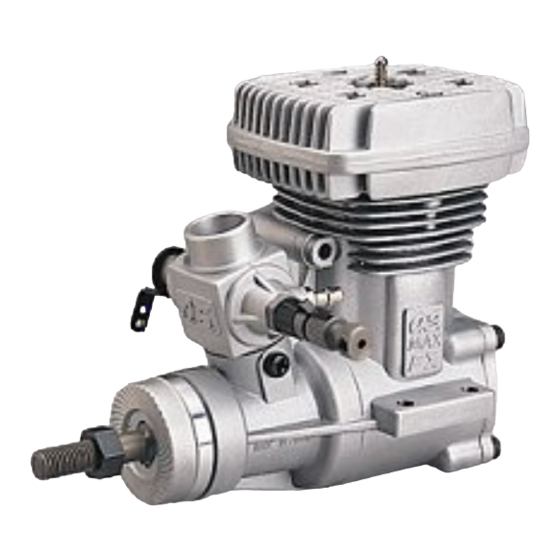
Page 7: Introduction
INTRODUCTION BASIC ENGINE PARTS The MAX-46FX-H RING is a high- Heatsink Head Glowplug performance engine that has been developed expressly for "medium-sized" Carburettor radio-controlled helicopters. Typr 40E Note: Because of initial tightness, a standard electric starter may have difficulty in Cover Plate rotating the engine when cold, before it has been adequately run-in. -
Page 8: Installation
Glow plug INCORRECT Washer INSTALLATION OF THE ENGINE The under-surfaces of all O.S. engine beam Top surfaces are not in the Top surfaces are not mounting lugs are precision machined flat and same plane. in the same plane. -
Page 9: Installation Of Cooling Fan
BEFORE STARTING INSTALLATION OF COOLING FAN Tools, accessories, etc. As supplied the MAX-46FX-H is equipped with a The following items are necessary for operating the conventional drive hub, keyed to flats on each side of engine. the crankshaft. However, some helicopters require 1 Fuel this to be replaced by a taper collet for cooling fan Model glowplug engine fuel of good quality, preferably... - Page 10 Warning (Very hot) 6 Fuel bottle or pump Never touch For filling the fuel tank, a simple, nichrome wire polyethylene "squeeze" bottle, with while the battery a suitable spout,is all that is Fuel bulb is connected. required. Alternatively, one of the purpose-made manual or electric Resistance coil fuel pumps may be used to transfer...
-
Page 11: Facts About Glowplugs
9 Hexagon starting shaft FACTS ABOUT GLOWPLUGS This shaft mounted on an Since the compatibility of glowplug and fuel may have electric starting motor is driven a marked effect on performance and reliability, it may into the main body of a be worthwhile to choose the R/C type plug found helicopter to turn the engine. -
Page 12: Fuel 10
However, plug life can be extended and engine FUEL performance maintained by careful use, i.e.: Select, by practical tests, the most suitable fuel from • Install a plug suitable for the engine. among the best quality fuels available in your country •... -
Page 13: Carburetor Controls
CARBURETOR CONTROLS Mixture Control Valve (MIxture Control Screw) With a fixed-wing model, power failure is rarely a Needle Valve serious threat to the safety of the aircraft since it can Throttle Lever usually glide down to a safe landing. In a helicopter, on the other hand, it is vitally imporant that the engine keeps running and that there is a quick and reliable response to the throttle in order to ensure safe ascent... -
Page 14: Starting 13
Checking the rotating direction of the starter STARTING Make sure that the starter rotates Be sure to use a muffler pressurized fuel feed. Use to the direction shown in the the same fuel as you intend to employ for actual sketch. -
Page 15: Running-In
Starting RUNNING-IN ("Breaking-in") Connect the battery to the glowplug and start the engine by applying the starter. When started, All internal-combustion engines benefit, to some switch off the starter and withdraw the starting degree, from extra care when they are run for the first shaft after making sure the rotation of the starter few times known as running-in or breaking-in. -
Page 16: Adjustment 15
Set up the throttle linkage as follows: ADJUSTMENT With the transmitter throttle trim lever fully The following adjustments are approximately correct retarded, adjust the throttle servo linkage so that the throttle rotor is (a) fully open when the when using a fuel containing 25% lubricant and 10- transmitter throttle stick is fully advanced and (b) 30% nitromethane. - Page 17 lf, at this time, the engine is slow to pick up and Hover the model and actuate the throttle to produces an excess of exhaust smoke, the mixture observe response over the medium speed range. is too rich. Correct this condition by turning the lf the engine smokes excessiveIy and throttle Mixture Control Screw clockwise.
-
Page 18: Adjustment
exhaust unduly smoky and the model fails to reach Readjustments should therefore be carried out as expected straight line speed, the mixture is too rich follows: and the Needle Valve setting will need to be lf the mid-range throttle response is not rapid and reduced. -
Page 19: Subsequent Readjustments
SUBSEQUENT READJUSTMENTS CARBURETOR CLEANLINESS The correct functioning of the carburetor depends on Once the engine has been run-in and the carburetor its small fuel orifices remaining clear. controls properly set up, it should be unnecessary to The minute particles of foreign matter that are present alter the mixture settings, except to make minor adjustments to the Needle Valve occasionally, to take in any fuel can easily partially obstruct these orifices... -
Page 20: Adjusting Chart
ADJUSTING CHART Open the Needle Valve 2 turns from the fully closed position. Make sure that the Mixture Control Valve is at the factory setting. Start the engine Warm up the engine Observe the mixture condition while "floating" the model Rich mixture Lean mixture Turn the Mixture... -
Page 21: Installation Of Throttle Servo
INSTALLATION OF THROTTLE SERVO After fitting the engine in the helicopter, please observe the following recommendations when linking the throttle servo to the carburetor. When the throttle is fully open or fully closed, the throttle lever angle should not be more than 45˚ either side of the mid-point of its travel (and where it is at a 90˚... -
Page 22: Care And Maintenance
CARE AND MAINTENANCE The minute particles of foreign matter, that are Finally, inject some after-run oil into the engine. present in any fuel may, by accumulating and Rotate the engine a few times by hand, to make sure partially obstructing fuel flow, cause engine that it is free, and then with an electric starter for 4 performance to become erratic and unreliable. -
Page 23: Engine Exploded View & Parts List 22
-46FX-H EXPLODED VIEW RING C.M3X12 N.+M3.5X6 C.M3X8 Type of screw … … Cap Screw M Oval Fillister-Head Screw … … … Flat Head Screw N Round Head Screw S Set Screw... -
Page 24: Parts List
ENGINE PARTS LIST Description Code No. Heatsink Head 25604200 Cylinder Liner 25603100 Piston Ring 25303400 Piston 25603200 Piston Pin 24806301 Piston Pin Retainer 24817100 Connecting Rod 25305002 Carburetor Complete 40C 25683000 Propeller Nut 23210007 Drive Washer 25608000 Thrust Washer 46120000 Crankshaft Ball Bearing(Front) 26731002 Crankcase... - Page 25 -46FX-H (G) / HG (L/S) RING RING EXPLODED VIEW C.M3X12 N.+M3.5X6 C.M3X8 Type of screw … … Cap Screw M Oval Fillister-Head Screw … … … Flat Head Screw N Round Head Screw S Set Screw...
-
Page 26: Parts List
ENGINE PARTS LIST Code No. Description Heatsink Head 25604210 Cylinder Liner 25603100 Piston Ring 25303400 Piston 25603200 24806301 Piston Pin Piston Pin Retainer 24817100 25305002 Connecting Rod Carburetor Complete 40C 25683000 Propeller Nut 23210007 Drive Hub(H (G)) 25608000 RING 0 -A Propeller Washer(HG(L/S) 23009006 RING... -
Page 27: Carburetor Exploded View & Parts List
CARBURETOER PARTS LIST & EXPLODED VIEW Description Code No. 22781410 Throttle Lever Assembly 1 -1 1 -1 22781420 Throttle Lever Retaining Screw 25683200 Carburetor Rotor 25683100 Carburetor Body 3 -1 "O" Ring (2pcs.) 24881824 Rotor Spring 26781506 3 -1 45581820 Rotor Guide Screw 22681953 Fuel Inlet... -
Page 28: Three View Drawing
46FX-H THREE VIEW DRAWING MAX- RING 4- φ 3.7 17.5 SPECIFICATIONS 7.45 cc ( 0.455 cu.in. ) Displacement 22.0mm ( 0.866 in. ) Bore 19.6mm ( 0.772 in. ) Stroke Practical R.P.M. 2,000 17,000 r.p.m. Power output 1.62 bhp / 16,000 r.p.m. Weight 385g(13.6oz.) 2- φ... -
Page 29: O.s. Genuine Parts & Accessories
O.S. GENUINE PARTS & ACCESSORIES ° SILENCER SILENCER 90 O.S. TAPER COLLET 873 SILENCER EXTENSION ADAPTOR ADAPTOR GLOW PLUGS (25608100) (25425000) (25425500) No.8 (25425600) (71608001) (71605100) CRANKSHAFT LOCK WASHER LONG SOCKET WRENCH NON-BUBBLE SUPER FILTER WITH PLUG GRIP CLAMP 3246 (10set) WEIGHT (72403050) - Page 30 6-15 3-Chome Imagawa Higashisumiyoshi-ku Osaka 546-0003, Japan TEL. (06) 6702-0225 FAX. (06) 6704-2722 URL : http://www.os-engines.co.jp Copyright 2001 by O.S.Engines Mfg. Co., Ltd. All rights reserved. Printed in Japan. 080101...
Need help?
Do you have a question about the MAX-46FX-Hring Series and is the answer not in the manual?
Questions and answers