Table of Contents
Advertisement
It is of vital importance, before attempting to operate
your engine, to read the general 'SAFETY
INSTRUCTIONS AND WARNINGS' section on
pages 2-6 of this booklet and to strictly adhere to the
advice contained therein.
Also, please study the entire contents of this
instruction manual, so as to familiarize yourself
with the controls and other features of the engine.
Keep these instructions in a safe place so that you
may readily refer to them whenever necessary.
It is suggested that any instructions supplied with
the aircraft, radio control equipment, etc., are
accessible for checking at the same time.
2-6
RUNNING -IN, IDLING ADJUSTMENT CHART
7-8
9
10
11-14
15-17
18-19
ENGINE EXPLODED VIEW & PARTS LIST
20-21
CARBURETOR EXPLODED VIEW & PARTS LIST
22
23
1
CONTENTS
24-27
28-31
34-35
36-37
38-39
40-41
42-43
32
33
44
Advertisement
Table of Contents

Related Manuals for O.S. engine MAX-75AX-BE


Summary of Contents for O.S. engine MAX-75AX-BE
-
Page 1: Table Of Contents
CONTENTS SAFETY INSTRUCTIONS AND WARNINGS STARTING 24-27 ABOUT YOUR O.S. ENGINE RUNNING -IN, IDLING ADJUSTMENT CHART 28-31 ENGINE CONSTRUCTION, MIXTURE CONTROL VALVE ADJUSTMENT NOTES WHEN APPLYING AN ELECTTRIC STARTER... -
Page 2: Safety Instructions And Warnings About Your O.s. Engine
As owner, you, alone, are responsible for the safe operation of your engine, so act with discretion and care at all times. If at some future date, your O.S. engine is acquired by another person, we would respectfully request that these instructions are also passed on to its new owner. - Page 3 NOTES This engine was designed for model If you remove the glowplug from the engine aircraft. Do not attempt to use it for any and check its condition by connecting the other purpose. battery leads to it, do not hold the plug with bare fingers.Use an appropriate tool or a Mount the engine in your model securely, folded piece of cloth.
-
Page 4: Engine Construction
NOTES Adjust the throttle linkage so that the engine For their safety, keep all onlookers stops when the throttle stick and trim lever (especially small children) well back (at on the transmitter are fully retarded. least 20 feet or 6 meters) when preparing Alternatively, the engine may be stopped by your model for flight. -
Page 5: Notes When Applying An Electtric Starter
NOTES WHEN APPLYING AN ELECTRIC STARTER Do not over-prime. This could cause a hydraulic lock and damage the engine on application of the electric starter. If over-primed, remove glowplug, close needle-valve apply starter to pump out surplus fuel. Cover the head with a rag to prevent pumped out fuel from getting into your eyes. -
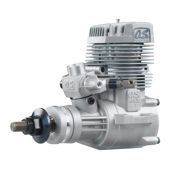
Page 6: Basic Engine Parts
BASIC ENGINE PARTS Glowplug Cylinder head Carburetor Type 61A-BE Cover Plate Propeller washer Propeller nut Beam Mount Lock nut Crankshaft Crankcase Drive Hub BEFORE STARTING Warning: Tools, accessories, etc. The following items Make sure that the propeller is well are necessary for operating the engine. balanced. - Page 7 FUEL Fuel Tank A fuel tank of approximately Use the O.S. Bio-Ethanol fuel (BE-1). 160~180cc capacity is suggested. Other fuel cannot be used with this engine. This allows around 10-12 minutes flying time, Do not use conventional methanol based glow dependent upon, the size of propeller and on fuel, or the engine will not run properly and the amount of full-throttle to part-throttle...
-
Page 8: Installation
LONG SOCKET WRENCH WITH PLUG GRIP TOOLS Recommended easy removal HEX Screwdriver replacement of the angled and recessed Necessary for engine installation. glowplug, the O.S.Long Socket Wrench 1.5mm, 2.5mm incorporates a special grip. Phillips Screwdriver No.2, etc. End Wrenches 12mm, 14mm etc. SCREWDRIVER Necessary for carburetor adjustments. - Page 9 How to fasten the mounting screws. ● Make sure that these mounting beams are Hardwood mounting beams accurately aligned and firmly integrated with Tighten second nut the airframe, reinforcing the adjacent 3mm steel nuts firmlydown onto first nut. structure to absorb vibration. Use 4mm or Tighten this nut first.
-
Page 10: Installation Of The Standard Accessories
INSTALLATION OF THE STANDARD ACCESSORIES INSTALLING THE GLOWPLUG NEEDLE-VALVE EXTENSION The needle-valve supplied with this engine is designed to incorporate an extension so that, when the engine is enclosed within the Install washer on glowplug fuselage, the needle-valve may be adjusted insert carefully into... -
Page 11: Fuel Tank Location
FUEL TANK LOCATION Suggested fuel tank capacity is approx 160- Locate the fuel tank so that the center line of 180cc. This will allow 10-12 minute flights. the tank is 10 to 15mm below the center line of the needle-valve. Make sure that the tank is well rinsed out with methanol or glow fuel before installation Be sure to use a pressurized fuel system by... -
Page 12: Mixture Controls
MIXTURE CONTROLS Two mixture controls are provided on this Needle Valve Carburetor. The Needle Valve When set to produce maximum power at full throttle, this establishes the basic fuel/air Mixture Control Valve mixture strength. The correct mixture is then maintained by the carburetor's built-in Mixture Control Valve of the carburetor is set at automatic mixture control system to cover basic position ( a little on the rich side) at the... -
Page 13: Starting
STARTING Be sure to use an electric starter to Element glows when energized. start the engine. Pliers Never fail to check the tightness of screws and nuts, especially engine mounting and moving parts (e.g. throttle lever). Replace the plug when the element does not glow or is burnt out. - Page 14 It is necessary to warm the engine up well so When the engine is started, open the throttle that the fuel may vaporize sufficiently in order slowly and adjust for the maximum r.p.m. for the engine to run steadily at maximum With this needle-valve setting, the mixture is r.p.m.
- Page 15 RUNNING-IN (“Breaking-in”) All internal-combustion engines benefit from Install the engine with the propeller intended extra care when they are run for the first few for your model. Open the needle-valve to the timesknown as running-in or breaking-in. advised starting setting and start the engine. This allows the working parts to mate together If the engine stops when the glow plug under...
- Page 16 Needle-valve adjustment diagram Note : Practical best(optimum) needle-valve setting This diagram is for reference purposes only. Clear, high-pitched two-stroke Maximum rpm Actual needle positions may exhaust note setting("Lean"). differ from those shown. Intermittent, high-pitched STARTING two-stroke note superimposed "Rich" needle-valve on low "four-stroke"...
-
Page 17: Mixture Control Valve Adjustment
MIXTURE CONTROL VALVE ADJUSTMENT With the engine running, close the throttle the screw clockwise gradually until the and allow it to idle for about five seconds, engine retains full power cleanly when the then open the throttle fully. If ,at this point, throttle is reopened. -
Page 18: Trouble Shooting When The Engine Fails To Start
TROUBLE SHOOTING WHEN THE ENGINE FAILS TO START Four key points For quick, reliable starting, the following four conditions are required. 1 Good compression. 2 Adequate "glow" at glowplug. 3 Correct mixture. 4 Sufficient electric starter rotating speed. If the engine fails to start, or does not keep running after being started, check symptoms against the following chart and take necessary corrective action. -
Page 19: Care And Maintenance
CARE AND MAINTENANCE Please pay attention to the matters Install a fuel filter to prevent foreign matter in described below to ensure that your engine the fuel container from entering the fuel tank. serves you well in regard to performance, O.S. -
Page 21: Carburetor Exploded View
CARBURETOR EXPLODED VIEW N.+M3x6 N.+M3.5x6 S.M3X3 Type of screw C...Cap Screw M...Oval Fillister-Head Screw F...Flat Head Screw N...Round Head Screw S...Set Screw CARBURETOR PARTS LIST Code No. Description 22081408 Throttle Lever Assembly 22081313 Assembly Screw 25781200 Carburetor Rotor 25781600 Mixture Control Valve Assembly 46066319 "O"... -
Page 22: O.s. Genuine Parts & Accessories
O.S. GENUINE PARTS & ACCESSORIES O.S.GLOW PLUG O.S. Bio-Ethanol RADIAL MOTOR MOUNT PROPELLER glow fuel LOCKNUT SET BE-3 (71905200) BE-1(4L) (For Spinner) (71668100) (79710000) 5/16-M4 (45910200) SILENCER EXTENSION ADAPTORS NON-BUBBLE NON-BUBBLE WEIGHT WEIGHT (71531000) (71531010) Width Screw hole pitch 14.5mm 42.0mm (26625340) (26625500) -
Page 23: Three View Drawing
THREE VIEW DRAWING 105.4 SPECIFICATIONS Displacement 12.29 cc / 0.75 cu.in. Bore 25.8 mm / 1.016 in. Stroke 23.5 mm / 0.925 in. Practical R.P.M. 2,300-10,000 r.p.m. Power output 1.2 ps / 1.22 hp / 10,000r.p.m. Weight 583 g / 20.56 oz. E-4040 Silencer 178 g / 6.28 oz.
Need help?
Do you have a question about the MAX-75AX-BE and is the answer not in the manual?
Questions and answers