Table of Contents
Advertisement
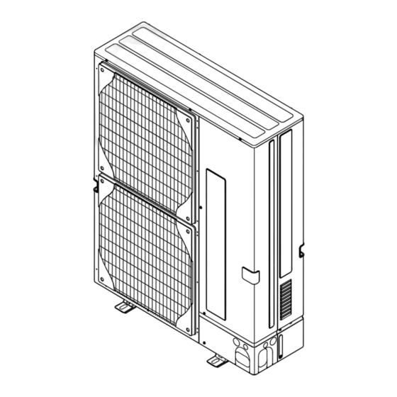
SPLIT-TYPE, AIR TO WATER HEAT PUMP
SERVICE MANUAL
R410A
[Model name]
PUHZ-HRP200YKA
PUHZ-HRP200YKA
[Service Ref.]
PUHZ-HRP200YKA
Note:
• This manual describes only
service data of the outdoor unit.
• Refer to Technical manual of
ATW, I/F and FTC.
• RoHS compliant products have
<G> mark on the spec name
plate.
CONTENTS
1. SAFETY PRECAUTION ........................................... 2
2. SPECIFICATIONS ...................................................... 5
3. DATA .............................................................................. 7
4. OUTLINES AND DIMENSIONS ............................ 9
5. WIRING DIAGRAM .................................................. 10
6. WIRING SPECIFICATIONS .................................. 11
7. REFRIGERANT SYSTEM DIAGRAM .................... 13
8. TROUBLESHOOTING ............................................ 14
9. DISASSEMBLY PROCEDURE ............................ 47
PARTS CATALOG (OCB466)
November 2009
No. OCH466
Advertisement
Table of Contents

Subscribe to Our Youtube Channel
Related Manuals for Mitsubishi Electric PUHZ-HRP200YKA


Summary of Contents for Mitsubishi Electric PUHZ-HRP200YKA
-
Page 1: Table Of Contents
SERVICE MANUAL R410A [Model name] [Service Ref.] Note: • This manual describes only PUHZ-HRP200YKA PUHZ-HRP200YKA service data of the outdoor unit. • Refer to Technical manual of ATW, I/F and FTC. • RoHS compliant products have <G> mark on the spec name plate. -
Page 2: Safety Precaution
SAFETY PRECAUTION 1-1. ALWAYS OBSERVE FOR SAFETY Before obtaining access to terminal, all supply circuits must be disconnected. Preparation before the repair service. • Prepare the proper tools. • Prepare the proper protectors. • Provide adequate ventilation. • After stopping the operation of the air conditioner, turn off the power-supply beaker. •... - Page 3 [1] Cautions for service (1) Perform service after recovering the refrigerant left in unit completely. (2) Do not release refrigerant in the air. (3) After completing service, charge the cycle with specified amount of refrigerant. [2] Additional refrigerant charge When charging directly from cylinder ·...
- Page 4 1-3. CAUTIONS FOR REFRIGERANT PIPING WORK Tools for R410A (The following table shows whether conventional tools can be used or not.) Tools and materials R410A tools Can R22 tools be used? Can R407C tools be used? Gauge manifold Air purge, refrigerant charge Tool exclusive for R410A Charge hose and operation check...
-
Page 5: Specifications
SPECIFICATIONS 2-1. SPECIFICATION 2.-1-1. PUHZ-HRP200YKA <Reference data> Plate heat exchanger (ACH50-50 plates) *2pcs [connected in parallel] Rating conditions Nominal water fl ow L/min 65.9 Nominal operating condition Heating Capacity 23.0 (A7/W35) Heating (A2/W35) 3.65 Outside air temperature (Dry-bulb) + 2 °C Power input 6.31... -
Page 6: Outdoor Unit
2-1-2. Outdoor unit Model name PUHZ-HRP200YKA Running current Heating(A7/W35) Cooling(A35/W7) 13.7 Power factor Heating(A7/W35) Cooling(A35/W7) Power supply (phase, cycle, voltage) 3 phase, 50 Hz, 400 V Max. current 25.0 Breaker size Outer casing Galvanized plate External fi nish Munsell 3Y 7.8/1.1... -
Page 7: Data
| C-E | or | D-E | Within 15 8 m and less HRP200 : A+B+C(+D)(+E) ≤ 80 m * “D” is for triple“. * “E” is for four (quadruple). 3-2. NOISE CRITERION CURVES PUHZ-HRP200YKA SPL(dB) MODE LINE COOLING HEATING MICROPHONE NC-70... -
Page 8: Standard Operation Data
(ACH50-50 plates) o 2 pcs [connected in parallel] Cooling Heating Mode (A35/W7) (A7/W35) Capacity 20,000 23,000 Input 9.01 6.31 Outdoor unit PUHZ-HRP200YKA Phase, Hz 3, 50 Voltage Current 13.7 Discharge pressure Suction pressure Discharge temperature ºC Condensing temperature ºC Suction temperature ºC... -
Page 9: Outlines And Dimensions
OUTLINES AND DIMENSIONS Unit: mm PUHZ-HRP200YKA... -
Page 10: Wiring Diagram
WIRING DIAGRAM PUHZ-HRP200YKA SYMBOL NAME SYMBOL NAME SYMBOL NAME Terminal Block<Power Supply> P.B. Switch Power Circuit Board Terminal Block<Indoor/Outdoor> Switch < Pump Down > SC-U/V/W Connection Terminal < U/V/W-Phase > Motor for Compressor TB-L1/L2/L3 Connection Terminal < L1/L2/L3-Power supply >... -
Page 11: Wiring Specifications
WIRING SPECIFICATIONS * With Heater model only For Heater A Indoor unit B Outdoor unit C Remote controller D Main switch (Breaker) E Earth For Heater For Heater For Heater For Power For Power Note: Only for Air to water application When multiple indoor units (Hydro boxes) are connected to the outdoor unit, wire the PCB of either one of the indoor unit and the outdoor unit (S1,S2,S3). - Page 12 INDOOR-OUTDOOR CONNECTING CABLE (HRP200) Cross section of cable Wire size (mm Number of wires Polarity L (m)*6 Round Clockwise : S1-S2-S3 (30) *Pay attention to stripe of yellow and green Flat Not applicable Not applicable (Because center wire has no cover finish) Flat From left to right : S1-Open-S2-S3 (18)
-
Page 13: Refrigerant System Diagram
Refrigerant flow in cooling Refrigerant flow in heating LEV-C Symbol Part name Detail COMP Compressor DC inverter scroll compressor (Mitsubishi Electric Corporation) H/P SW High pressure switch (63H) For protection (OFF: 4.15MPa) L/P SW Low pressure switch (63L) For protection (OFF: -0.03MPa) REV/V... -
Page 14: Troubleshooting
TROUBLESHOOTING 8-1. TROUBLESHOOTING <Error code display by self-diagnosis and actions to be taken for service (summary)> Present and past error codes are logged and displayed on the control board of outdoor unit. Actions to be taken for service, which depends on whether or not the trouble is reoccurring at service, are summarized in the table below. Check the contents below before investigating details. - Page 15 8-2. CHECK POINT UNDER TEST RUN Before test run • After installation of outdoor unit, piping work and electric wiring work, re-check that there is no water leakage, loosened con- nections and incorrect polarity. • Measure impedance between the ground and the power supply terminal block (L, N) on the outdoor unit by 500 V Megger and check that it is 1.0 M or over.
-
Page 16: Self-Diagnosis Action Table
8-3. SELF-DIAGNOSIS ACTION TABLE <Abnormalities detected when the power is turned on> Abnormal point and detection method Judgment and action Error Code Case 1 No voltage is supplied to termi- 1 Check following items. nal block(TB1) of outdoor unit. a) Power supply breaker a) Power supply breaker is b) Connection of power supply terminal block turned off. - Page 17 Abnormal point and detection method Case Judgment and action Error Code Check disconnection or looseness or polarity Miswiring of Interface unit/Flow temp. Contact failure or miswiring of of Interface unit/Flow temp. controller-outdoor controller-outdoor unit connecting wire Interface unit/Flow temp. controller- unit connecting wire of Interface unit/Flow 1.
-
Page 18: Abnormalities Detected While Unit Is Operating
<Abnormalities detected while unit is operating> <Abnormalities detected while unit is operating> Abnormal point and detection method Judgment and action Error Code Case High pressure (High-pressure switch 1 Short cycle of indoor unit 1~6 Check indoor unit and repair defectives. 63H operated) 2 Clogged filter of indoor unit Abnormal if high-pressure switch 63H oper-... - Page 19 Abnormal point and detection method Judgment and action Error Code Case Open/short of outdoor unit thermistors 1 Disconnection or contact failure 1 Check connection of connector (TH3, TH32, (TH3, TH32, TH6, TH7, and TH8) of connectors TH7/6) on the outdoor controller circuit board. Abnormal if open or short is detected Outdoor controller circuit board: Check connection of connector (CN3) on the...
- Page 20 Abnormal point and detection method Judgment and action Error Code Case Outdoor fan motor 1 Failure in the operation of the 1 Check or replace the DC fan motor. Abnormal if rotational frequency of the fan DC fan motor motor is not detected during DC fan motor 2 Failure in the outdoor circuit 2 Check the voltage of the outdoor circuit operation.
- Page 21 Abnormal point and detection method Judgment and action Error Code Case Current sensor error or input current error 1 Disconnection of compressor 1 Correct the wiring (U W phase) to • • • Abnormal if current sensor detects –1.0A wiring compressor.
- Page 22 Error Code Abnormal point and detection method Cause Judgment and action Remote controller transmission error 1 Contact failure at transmission 1 Check disconnection or looseness of Inter- (E0)/signal receiving error (E4) wire of remote controller face unit/Flow temp. controller or transmis- 1 Abnormal if main or sub remote controller 2 All remote controllers are set sion wire of remote controller.
- Page 23 Error Code Abnormal point and detection method Case Judgment and action Interface unit/Flow temp. controller or 1 Contact failure of Interface unit/ 1 Check disconnection or looseness of Inter- outdoor unit communication error (Sig- Flow temp. controller or outdoor face unit/Flow temp. controller or outdoor nal receiving error) unit connecting wire unit connecting wire of Interface unit/Flow...
- Page 24 Error Code Abnormal point and detection method Cause Judgment and action Actual fl ow water temperature thermis- 1 Defective thermistor 1–3 Check resistance value of thermistor. 15.0k" tor (TH1) characteristics 9.6k" 1 The unit is in 3-minute resume 2 Contact failure of TB61 No.1-2 6.3k"...
- Page 25 8-4. TROUBLESHOOTING ■ These sounds can be heard when refrigerant and/or water is (are) fl owing A fl owing water sound or occasional hissing sound is heard. in the indoor unit or refrigerant pipe, or when the refrigerant and/or water is (are) chugging.
- Page 26 8-5. HOW TO CHECK THE PARTS PUHZ-HRP200YKA Parts name Check points TH3: Liquid pipe temperature Disconnect the connector then measure the resistance with a tester. TH4: Discharge (At the ambient temperature 10 ~30 ) temperature TH6: 2-phase pipe Normal Abnormal...
- Page 27 Check method of DC fan motor (fan motor / outdoor controller circuit board) Notes · High voltage is applied to the connecter (CNF1, 2) for the fan motor. Pay attention to the service. · Do not pull out the connector (CNF1, 2) for the motor with the power supply on. board and fan motor.) (It causes trouble of the outdoor controller circuit Self check...
- Page 28 8-6. HOW TO CHECK THE COMPONENTS <Thermistor feature chart> Low temperature thermistors • Thermistor <Liquid pipe> (TH3) • Thermistor <2-phase pipe> (TH6) • Thermistor <Ambient> (TH7) • Thermistor <Suction pipe> (TH32) Thermistor R0 = 15k' ± 3% B constant = 3480 ± 2% =15exp{3480( 273+t –...
-
Page 29: Linear Expansion Valve
Linear expansion valve (1) Operation summary of the linear expansion valve • Linear expansion valve opens/closes through stepping motor after receiving the pulse signal from the outdoor controller board. • Valve position can be changed in proportion to the number of pulse signal. <Connection between the outdoor controller board and the linear expansion valve>... - Page 30 (3) How to attach and detach the coil of linear expansion valve <Composition> Linear expansion valve is separable into the main body and the coil as shown in the diagram below. Main body Stopper Coil Lead wire <How to detach the coil> Hold the lower part of the main body (shown as A) firmly so that the main body does not move and detach the coil by pulling it upward.
- Page 31 8-7. TEST POINT DIAGRAM Outdoor controller circuit board PUHZ-HRP200YKA CN51 Forced defrost, detect history record reset, External signal output Demand control setting Function switch refrigerant address • Compressor operat- ing signal • Abnormal signal CNDM Model select 1 to 2:...
- Page 32 Outdoor noise filter circuit board PUHZ-HRP200YKA LI1, LI2, LI3, NI POWER SUPPLY LI1-LI2/LI-LI3/LI3-LI1 : AC380/400/415V input LI1-NI/LI2-NI/LI3-NI : AC220/230/240V input (Connect to the terminal block (TB1)) Connect to the earth Connect to the earth CNAC1, CNAC2 AC220/230/240V (Connect to the...
- Page 33 Outdoor power circuit board Brief Check of POWER MODULE W Usually, they are in a state of being short-circuited if they are broken. PUHZ-HRP200YKA Measure the resistance in the following points (connectors, etc.). If they are short-circuited, it means that they are broken.
-
Page 34: Function Of Switches, Connectors And Jumpers
8-8. FUNCTION OF SWITCHES, CONNECTORS AND JUMPERS Function of switches Type Action by the switch operation Function Effective timing Switch switch When compressor is working Forced defrost 1 Start Normal in heating operation. 1 Abnormal history clear Clear Normal off or operating 1 2 3 4 5 6 1 2 3 4 5 6... - Page 35 Type of Action by the switch operation Switch Function Effective timing Switch No function — — — Power failure Auto recovery No auto recovery When power supply ON automatic recovery 2 No function — — — 3,4,5 Model select Following SW5-6 reference Power consumption SW7-1 SW7-2...
- Page 36 Special function (a) Low-level sound priority mode (Local wiring) Unit enters into Low-level sound priority mode by external signal input setting. Inputting external signals to the outdoor unit decreases the outdoor unit operation sound 3 to 4 dB lower than that of usual. Adding a commercial timer or on-off switch contactor setting to the CNDM connector which is optional contactor for demand input located on the outdoor controller board enables to control compressor operation frequency.
- Page 37 <Display function of inspection for outdoor unit> The blinking patterns of both LED1 (green) and LED2 (red) indicate the types of abnormality when it occurs. Types of abnor- mality can be indicated in details by connecting an optional part “A-Control Service Tool (PAC-SK52ST)” to connector CNM on outdoor controller board.
- Page 38 Indication Error Error Outdoor controller board Contents Inspection method code LED1 (Green) LED2 (Red) 3 blinking 1 blinking Abnormality of shell thermostat Check if stop valves are open. Check if connectors (TH4, LEV-A, and LEV-B) on outdoor controller and discharging temperature (TH4) board are not disconnected.
- Page 39 <Outdoor unit operation monitor function> [When optional part “A-Control Service Tool(PAC-SK52ST)” is connected to outdoor controller board(CNM)] Digital indicator LED1 displays 2 digit number or code to inform operation condition and the meaning of error code by controlling DIP SW2 on “A-Control Service Tool”. Operation indicator SW2 : Indicator change of self diagnosis Explanation for display...
- Page 40 SW2 setting Display detail Explanation for display Unit Pipe temperature / Liquid(TH3) −40~90 −40~90 (When the coil thermistor detects 0: or below, “–” and temperature are displayed by turns.) (Example) When −10:; 2 3 4 5 6 0.5 secs. 0.5secs. 2 secs.
- Page 41 SW2 setting Display detail Explanation for display Unit Pipe temperature / Liquid (TH3) on error −40~90 occurring (When the coil thermistor detects 0: or below, “–” −40~90 and temperature are displayed by turns.) (Example) When −15:; 0.5 secs. 0.5secs. 2 secs. 2 3 4 5 6 Compressor temperature (TH4) or 3~217...
- Page 42 SW2 setting Display detail Explanation for display Unit The number of connected indoor units (The number of connected indoor units are dis- played.) Unit 2 3 4 5 6 Capacity setting display Displayed as an outdoor capacity code. Model Code HRP200 Code display...
- Page 43 SW2 setting Display detail Explanation for display Unit Pressure saturation temperature (T −39~88 63HS −39~88 (When the temperature is 0: or less, “–” and temperature are displayed by turns.) 2 3 4 5 6 Ambient temperature (TH7) −39~88 −39~88 (When the temperature is 0: or less, “–” and temperature are displayed by turns.) 2 3 4 5 6 Outdoor heatsink temperature (TH8)
- Page 44 SW2 setting Display detail Explanation for display Unit 0~255 Capacity save (When the capacity is 100% hundreds digit, tens digit 0~255 and ones digit are displayed by turns.) (Example) When 100%; When there is no setting 0.5 secs. 0.5secs. 2 secs. of capacity save “100”...
- Page 45 SW2 setting Display detail Explanation for display Unit Actual water temperature (TH1) on error 8~39 occurring 8~39 2 3 4 5 6 Pipe temperature / Liquid (TH2) on error −39~88 occurring (When the temperature is 0°C or less, “–” and −39~88 temperature are displayed by turns.) (Example) When −15°C;...
- Page 46 Explanation for display Unit SW2 setting Display detail Thermo-on time until error stops 0~999 0~999 (When it is 100 minutes or more, hundreds digit, tens digit and ones digit are displayed by turns.) (Example) When 415 minutes; Minute 0.5 secs. 0.5secs.
-
Page 47: Disassembly Procedure
DISASSEMBLY PROCEDURE PUHZ-HRP200YKA OPERATING PROCEDURE PHOTOS & ILLUSTRATION 1. Removing the service panel and top panel Photo 1 Top panel Top panel fixing screws (1) Remove 3 service panel fixing screws (5 × 10) and slide the hook on the right downward to remove the service Service panel panel. - Page 48 PHOTOS OPERATING PROCEDURE 4. Removing the thermistor <Outdoor 2-phase pipe> (TH6) Photo 5 Thermistor (1) Remove the service panel. (See Photo 1.) <Outdoor 2-phase pipe>(TH6) (2) Remove the top panel. (See Photo 1.) (3) Disconnect the connectors, TH6 and TH7 (red), on the Electrical controller circuit board in the electrical parts box.
- Page 49 OPERATING PROCEDURE PHOTOS 7. Removing the 4-way valve coil (21S4) and linear expan- Figure 1 sion valve coil (LEV-A, LEV-B, LEV-C) (1) Remove the service panel. (See Photo 1.) Linear expansion valve coil (LEV-C) Linear expansion valve (2) Remove the top panel. (See Photo 1.) (3) Remove the electrical parts box.
- Page 50 OPERATING PROCEDURE PHOTOS 10. Removing the high pressure switch (63H) and low pres- Photo 8 sure switch (63L) (1) Remove the service panel. (See Photo 1.) (2) Remove the top panel. (See Photo 1.) (3) Remove 3 right side panel fixing screws (5 × 10) in the rear of the unit and remove the right side panel.
- Page 51 PHOTOS OPERATING PROCEDURE Photo 10 12. Removing the power receiver (1) Remove the service panel. (See Photo 1.) Power receiver (2) Remove the top panel. (See Photo 1.) (3) Remove 2 front cover panel fixing screws (5 × 10) and remove the front cover panel.
- Page 52 HEAD OFFICE : TOKYO BLDG., 2-7-3, MARUNOUCHI, CHIYODA-KU, TOKYO 100-8310, JAPAN Copyright 2009 MITSUBISHI ELECTRIC ENGINEERING CO., LTD. Distributed in Nov. 2009 No. OCH466 PDF 7 Made in Japan New publication, effective Nov. 2009 Specifications subject to change without notice...
Need help?
Do you have a question about the PUHZ-HRP200YKA and is the answer not in the manual?
Questions and answers