Table of Contents
Advertisement
Advertisement
Table of Contents

Related Manuals for Global JUNIOR V4

Summary of Contents for Global JUNIOR V4
- Page 1 JUNIOR V4 INSTALLATION & COMMISSIONING MANUAL FEBRUARY 19, 2007 REVISION 1.0...
-
Page 2: Table Of Contents
CONTENTS OVERVIEW Introduction........................Key Features........................Access Levels........................Typical System Schematic....................Power Requirements......................Battery Requirements....................... ABS box information....................... Identifying Components....................EN54 Information......................Recommended Cables....................Analogue Loops, Conventional Sounders and Data Loops.......... Limitations........................Definitions........................INSTALLATION Introduction........................Panel..........................Mains Power Connection..................Other Panel connections..................Repeaters........................ - Page 3 CONTENTS COMMISSIONING (cont...) Getting The System Running(cont...)................... Analogue Loop Monitoring..................Open Circuit Test.................... Conventional Sounder Monitoring................Detector Tests......................Detector Tests By Zone..................Unassigned Detector Test................. Wrapping Up Installation And Commissioning..............Battery Fault Message Test..................Power Failure Test..................... ADVANCED FUNCTIONALITY Programming Functions General..................Complete List Of Functions..................
- Page 4 6-1-3 Set Selective Disablement................6-1-4 Set Device Reporting Details............... 6-1-5 Set Immediate Evacuate for Device............. 6-1-6 Device Activation Overrides Delays............. 6-1-7 Inhibit Auxiliary Relays................6-1-8 Global Sensitivity Set-up................6-1-9 Configure Timed Sensitivity................Other Device options....................6-2-1 Select Device Heat Grade................
- Page 5 CONTENTS 7 Monitor Device Counts & Test .................. 7-1 Device Count, Type & Value..................7-2 Test Sounders......................7-3 Sounders on Test Activation..................7-4 Test Zones........................ 7-6 Light LED on device....................8 General........................8-1 Time/Date & Timers....................8-1-1 Set Date & Time..................8-1-2 Define Day &...
-
Page 6: Introduction
OVERVIEW Introduction This document covers the installation and commissioning of a JUNiOr fire alarm panel. This document is intended for use by a competent, qualified, fire alarm installation engineer. The JUNiOr fire alarm system should be tailored to the building requirements. The complete system should be designed to meet all applicable regulations. -
Page 7: Access Levels
OVERVIEW ACCESS LEVEL 1 - General User Unless otherwise indicated, in order to enable the operation of a particular switch, either a valid User or Programming Access Code is required to be entered. The only exceptions are the following: 1- Lamp Test Switch 2- Queue Review Switches( Fire, fault, Test and Disabled) 3- Delays Active Switch. -
Page 8: Typical System Schematic
OVERVIEW Typical System Schematic I/O + 24 V VOLTAGE FREE NORMALLY OPEN CONTACTS NON-LATCHING ACTION REMOTE DISABLEMENT OF SELECTED DETECTORS CLASS CHANGE REMOTE EVAC. Loop 2 ALL AUX RELAYS RATED AT PC Loader AUXILIARY 50V AC/DC 1 AMP RESISTIVE Connections DB9 Female POWER SUPPLY Connector... -
Page 9: Power Requirements
OVERVIEW Power Requirements LIVE NEUTRAL EARTH MEANWELL MODEL: PS-45-27 DANGER 220 VOLTS Power Supply Specification - MEANWELL Model: PS-45-27 Mains supply voltage 85-264V 50/60 Hz Internal power supply Min. 20 V DC – Max. 30 V DC (28.5 V DC nominal) Max. Ripple 1 V peak-peak Total output current 1,7A @230Vac Supply and battery charger monitored... -
Page 10: Battery Requirements
OVERVIEW Battery Requirements The battery AH required are calculated from the following formula Quiescent current in mA of Standby time required in the panel with everything hours divided by 1000. connected. Alarm current in Amps Alarm time in hours (sounder load) Round up to the next available battery size. -
Page 11: Abs Box Information
OVERVIEW ABS box information 106 mm 273 mm VIEW FROM FRONT VIEW FROM SIDE VIEW FROM TOP VIEW FROM REAR Dimensions Size 273 (W) x 403 (L) x 106 (H) mm Weight without batteries 1,6 Kgs INSTALLATION & COMMISSIONING MANUAL - REVISION 1.0 - 19.FEB.2007... -
Page 12: Identifying Components
OVERVIEW Identifying Components Inside JUNiOr INSTALLATION & COMMISSIONING MANUAL - REVISION 1.0 - 19.FEB.2007... - Page 13 OVERVIEW Identifying Components JUNIOR-MB: JUNIOR MAIN BOARD FRONT VIEW REAR VIEW Junior Expansion Junior Expansion Loop Card Loop Card INSTALLATION & COMMISSIONING MANUAL - REVISION 1.0 - 19.FEB.2007...
- Page 14 OVERVIEW Identifying Components NOTE: Junior can only be networked with repeater panels. J-NET-INT-485-NEW INTERFACE FOR RS485 COMMUNICATION J-NET-INT-FO: FIBRE OPTIC INTERFACE J-NET-INT-TCP/IP INTERFACE FOR TCP/IP COMMUNICATION UNIOR -SIM: JUNiOr SIM CARD VIEW FROM FRONT NOTE: THROUGHOUT THE MANUAL, MALE FEMALE PIN ON THE 5 WAY MOLEX INDICATES WHICH PIN IS Nº1...
-
Page 15: En54 Information
OVERVIEW EN54 INFORMATION In accordance with EN54pt.2 1997/AC:1999 clause 13.7, the maximum number of sensors and/or manual call points in this panel, will not exceed 512 units. The Fire Detection Control Panel complies with the requirements of EN54 pt. 2 and 4 1997/AC:1999. -
Page 16: Recommended Cables
OVERVIEW Recommended Cables Analogue Loops, Conventional Sounders and Data Loops Fire rated Cables for Loops and Sounder Circuits AEI type Firetec Multicore Ref. F1C1 (1 mm ) to F1C2.5 (2.5 mm ) in 2 core AEI type Firetec Armoured Ref. F2C1 (1.5 mm ) to F2C2.5 (2.5 mm ) in 2 core AEI type Mineral Insulated Cable (all types up to 2.5 mm BICC types Mineral Insulated twin twisted conductor cables, Ref. -
Page 17: Definitions
OVERVIEW Definitions Analogue Loop The physical link, usually fireproof 2 conductor shielded wiring cable, forming a ring of interconnection between sensors and the detection panel. Cable form A connecting lead. Typically a length of flat cable with connectors at both ends. Conventional Sounder A Conventional Sounder is an audible output device that is connected to the Conventional Sounder outputs on the Panel. -
Page 18: Installation
INSTALLATION Introduction This section covers the physical installation of the system. It primarily focuses on the parts that are required and how they should be connected together. Do not connect the mains power or the batteries at this stage; commissioning the system is covered in the next section of this manual. Installation should always be performed in accordance with a system plan. -
Page 19: Panel Main Board - Connection Definitions
INSTALLATION JUNIOR MAIN BOARD Loop connections . A1 corresponds to Loop 1 and A2 to Loop 2 Conventional sounder circuit 1 Conventional sounder circuit 2 5 pin connector for RS485, Fibre-optic or TCP/IP (LAN) connection with repeater panel 5 pin connector for multiplexed zone LEDs or relays Auxiliary change-over relay output 1 (Activated by any fire present on the system, disabled by front button) Auxiliary change-over relay output 2... -
Page 20: Fitting Junior Expansion Loop Card
INSTALLATION Fitting Junior Expansion Loop Card This operation should only be performed by qualified personnel. Power to the panel should be completely removed, both primary and secondary (batteries) supplies, before the installation process of the card is initiated. After process is completed re-apply power to the panel. Panel should be in installation mode. -
Page 21: Data Loops
INSTALLATION Data Loops If the system includes mini-repeaters to allow remote viewing and control of the system, an RS422/485, Fibre Optic or TCP/IP connection may be used. For redundancy in the case of RS422/485 and Fibre Optic this can be wired in the form of a Loop, thus protecting the Data Loop from interruptions or short circuits by creating a bi-directional communications flow. -
Page 22: Panel Rs485
INSTALLATION Panel RS485 NOTE: Make all connections with the power turned off to avoid risk of permanent damage to the circuit boards. If a repeater panell is required, the appropriate interface board for the desired communications media must be installed in both the panel and repeater. JUNIOR PANEL CONNECTIONS LINKS J1 &... -
Page 23: Repeater Rs485
INSTALLATION Repeater RS485 NOTE: Make all connections with the power turned off to avoid risk of permanent damage to the circuit boards. The repeater connections to the RS485 Interface are basically the same as for the Panel. The placement of the RS485 interface inside the Mini-repeater differs from the Junior's since it is placed vertically. -
Page 24: Panel Fibre Optic
INSTALLATION Panel Fiber-Optic NOTE: Make all connections with the power turned off to avoid risk of permanent damage to the circuit boards. Connection is made using fibre optic cable instead of copper cable. The ends of the fibre must be terminated with ST™... -
Page 25: Repeater Fibre Optic
INSTALLATION Repeater Fiber-Optic NOTE: Make all connections with the power turned off to avoid risk of permanent damage to the circuit boards. The repeater connections to the Fibre-Optic Interface are basically the same as for the Panel. MINI-REP MB LINKS LK1 &... -
Page 26: Analogue Loop
INSTALLATION TCP/IP Connection The use of a TCP/IP network may require the support and co-operation of the end users IT department. Be sure that this support is available before deciding on this communications method For detailed TCP/IP connection information please refer to TCP/IP specific technical information and/or contact technical support at techs@globalfire.pt... -
Page 27: Conventional Sounders
INSTALLATION Conventional Sounders Conventional Sounders is the term used to describe conventional alarm sounders (or bells) connected directly to a Panel. Loop-powered Sounders are different and are connected to the Analogue Loop. Two Conventional Sounder circuits are provided on the Panel. More than one Conventional Sounder may be connected to each circuit. -
Page 28: Panel Batteries
INSTALLATION Panel Batteries It is recommended that the batteries are fitted at the end of commissioning the system otherwise it can be difficult to remove the power quickly if there is a problem. The batteries are connected to the JUNIOR main board in the Panel. This battery connection not only supplies the panel with power if the primary supply should fail, it also provides a charging output to maintain the batteries in a fully charged state. -
Page 29: Commissioning
COMMISSIONING Introduction Commissioning involves checking that all connections have been made properly and that all hardware is functioning correctly. This means the system must first be installed in accordance with the previous section of this manual. The panel is supplied set to ‘Installation mode’. In Installation Mode the green SYSTEM ON LED will flash on and off. - Page 30 COMMISSIONING The Panel Buttons BUZZER SILENCE (CONTROLS) The occurrence of any new fire or fault condition will initiate the operation of the internal buzzer. By pressing this switch, the operation of the buzzer will be stopped until a new fire or fault appears on the system.
- Page 31 COMMISSIONING The Panel Buttons (cont...) FIRE (QUEUE REVIEW) - General User Access (no code entry required) If more than one fire has been detected then the LED next to this button will flash. Press the button to step through all detected fires. Once all fires have been reviewed the LED will be constantly illuminated. Subsequent fires will be added to the end of the queue and the LED will start to flash again.
-
Page 32: Getting The Panel Running
COMMISSIONING Getting The Panel Running Apply AC power to the Panel. The LCD should display the software version and the message ‘INITIALIZING’. This will be followed by the date and time (and the company name if it has been set). Within a few seconds faults will be reported, these will overwrite the date and time (and company name). -
Page 33: Getting Into Programming Mode
COMMISSIONING Getting Into Programming Mode (Access Level 3) When the Panel is powered up it will be necessary to enter the panel programming mode. Familiarize yourself with this section before proceeding to the next section in the manual and powering up the panel. Programming mode is accessed via the front panel keypad as pictured below. - Page 34 COMMISSIONING Logging In To enter programming mode you need to log in. The Panel must be powered up and must have initialized itself i.e. NOT be showing the ‘INITIALIZING’ message. Press ENTER on the Keypad. You must now input your Installer access code. See page 6 Access Levels. You have unlimited attempts but if code entry is not started within 10 seconds then the panel will revert back to it’s default screen.
-
Page 35: Getting The System Running
COMMISSIONING Getting The System Running Ensure all connectors are firmly in place. Ensure that all connections are tight, with no stray strands of wire. Ensure that the SIM CARD is securely fitted in the Panel and Repeaters. If a Junior Expansion Loop Card has been added to the panel, please ensure that is securely fitted to the back of panel’s Main Board. -
Page 36: Learning Which Devices Are Fitted
COMMISSIONING Learning Which Devices Are Fitted Enter programming mode. (See page 6 Access Levels, Installer Access Code) If site specific data has NOT been pre-programmed then select function 8-3-1 Clear Customer Flash Memory and clear the customer flash. (You must NOT do this if you have been supplied with a SIM CARD pre-programmed with your site data.) Select function 8-3-2 Clear Non-Volatile RAM and clear the NVRAM. -
Page 37: Getting The System Running(Cont
COMMISSIONING Analogue Loop Monitoring Check that a short circuit or open circuit is detected on any of the Analogue Loops. Open Circuit Test Disconnect either the + or the - OUT connection for the Loop. The connection is found on the Panel's Main board. -
Page 38: Detector Tests
COMMISSIONING Detector Tests If the devices have been assigned to Zones (on a pre-programmed SIM CARD or via the programming menus) then it is possible to test the detectors with limited or no sounder operation. Detector Tests By Zone Before starting clear all faults, put the system into Active Mode, and press SYSTEM RESET. Enter programming mode and select function 7-3 Sounders on Test Activation. -
Page 39: Battery Fault Message Test
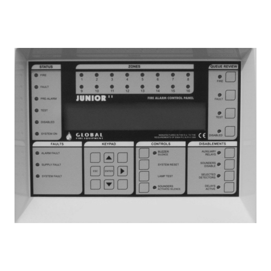
COMMISSIONING Battery Fault Message Test This test should be performed for each set of batteries. Test only the actual battery connections. Panel Main Board STATUS ZONES QUEUE REVIEW FIRE FIRE FAULT BLACK PRE-ALARM FAULT TEST TEST Panel Batteries DISABLED SYSTEM ON MANUFACTURED IN THE E.U. -
Page 40: Programming Functions General
6-1-5 Set Immediate Evacuate for Device 8-3-4 Calculate Program Flash Checksum 6-1-6 Device Activation Overrides Delays 6-1-7 Inhibit Auxiliary Relays 8-4 Other Features 6-1-8 Global Sensitivity Set-up 8-4-1 Active/Installation Mode 6-1-9 Configure Timed Sensitivity 8-4-2 Upload/Download Link to PC 8-4-4 Set User Access Code... -
Page 41: Keys To Use Within Functions
ADVANCED CONTENTS CONTENTS FUNCTIONALITY Keys To Use Within Functions Most functions use some or all of the following keys: are used to browse through items is often used to change fields (move the cursor). It will also be used, when required to toggle between Loops 1 and 2. -
Page 42: Specific Functions
ADVANCED CONTENTS CONTENTS FUNCTIONALITY Specific Functions 1 Review Historic Log All the functions associated with reviewing or printing events and settings. 1-1 Display Historic Log The panel logs all events in an internal event log. It can store a rolling 2000 entries. When it is full the latest entry is added and the oldest entry discarded. -
Page 43: Zones - Disable & Assign
ADVANCED CONTENTS CONTENTS FUNCTIONALITY 3 Zones - Disable & Assign All the functions associated with managing Zones 3-1 Disable Zones Allows you to disable or enable Zones. All devices in disabled Zones will cease to operate with the exception of the (audible) output from loop sounders. -
Page 44: Sounders - Disable & Assign
ADVANCED CONTENTS CONTENTS FUNCTIONALITY 4 Sounders - Disable & Assign 4-1 Sounder Configuration Allows selection of PRESET or PROGRAMMED sounder operation. Selecting PRESET (the default) will result in all sounders being operated; any Sounder Group settings will be ignored. NOTE: The Sounder Groups must be defined when PROGRAMMED is selected because the default group settings have all sounders set to silent. -
Page 45: Disable Sounders
ADVANCED CONTENTS CONTENTS FUNCTIONALITY 4-3 Disable Sounders Allows specific sounders to be disabled or Enabled. Disabled sounders will not be operated regardless of Sounder Configuration, Sounder Groups and evacuate requests. ‘E’ indicates enabled ‘D’ indicates disabled When programming mode is exited all sounders that have been disabled can be reviewed using the DISABLED (QUEUE REVIEW) button. -
Page 46: Sounder Delay Set-Up
4-6 Sounder Delay Set-up Allows the sounder delay to be set-up: The sounder delay can be set to GLOBAL MODE, ZONAL MODE or DISABLED. The sounder delay period is defined (to a maximum of 10 minutes). The devices that initiate a delayed sounder activation are specified. -
Page 47: Input/Output - Disable & Assign
ADVANCED CONTENTS CONTENTS FUNCTIONALITY 5 Input/Output - Disable & Assign Input/Output Analogue Loop device management. 5-1 Configure I/O Groups Allows an I/O Group to be established. The I/O Group can then be used for fire or fault reporting. 512 I/O Groups can be defined. First select the Group number then assign the I/O loop addresses. -
Page 48: Assign I/O Group To Device
ADVANCED CONTENTS CONTENTS FUNCTIONALITY 5-3 Assign I/O Group to Device Allows an I/O Group to be assigned to a detector. When the detector goes into alarm then the assigned I/O Group will be activated. NOTE: When a fire occurs all the I/O information for the detector in fire is combined: the device I/O Group is combined with the Common I/O Group and the four ‘first fire’... -
Page 49: Device Set-Up
ADVANCED CONTENTS CONTENTS FUNCTIONALITY 6 Device Set-up Allows specific settings to be selected for individual Analogue Loop devices. 6-1 General Settings common to all types of Analogue Loop devices. 6-1-1 Disable Loops Allows a specific Analogue Loop to be disabled or enabled. The default is enabled. All devices on the disabled loop will cease to operate with the exception of the (audible) output from loop sounders. -
Page 50: Set Device Reporting Details
6-1-6 Device Activation Overrides Delays Allows a detector to be set to override all zonal and global sounder and I/O delay timers. When this device is activated the Sounder Groups and I/O Groups associated with this device are also activated immediately (even if they were already queued for delayed activation). -
Page 51: Global Sensitivity Set-Up
CONTENTS CONTENTS FUNCTIONALITY 6-1-8 Global Sensitivity Set-up This function selects the sensitivity of all the detectors that have been set to GLOBAL SENSITIVITY. Different settings can be entered for weekdays and for Saturday and Sunday. Settings are : HIGH (alarm threshold of 45) -
Page 52: Other Device Options
Each individual detector has the following settings: NORMAL HIGH GLOBAL If GLOBAL is selected then, depending the day, the appropriate HIGH, LOW, NORMAL or TIMED setting is used (see functions 6-1-8 Global Sensitivity Set-up and 6-1-9 Configure Timed Sensitivity). HIGH NORMAL The Pre-alarm levels are always 10 below the alarm thresholds. -
Page 53: Discovery Specific
Settings are MODE 1, MODE 3, MODE 5 or GLOBAL. If GLOBAL is selected then, depending on the day, the appropriate HIGH, LOW, NORMAL or TIMED setting is used (see functions 6-1-8 Global Sensitivity Set-up and 6-1-9 Configure Timed Sensitivity). - Page 54 ADVANCED CONTENTS CONTENTS FUNCTIONALITY 6-3-5 Check for Devices Needing Service When activated this function reads the drift compensation value of every Discovery™ device connected to the system. Any devices that are close to their drift compensation limit (and therefore will shortly be in need of servicing) are reported via the normal fault reporting mechanism.
-
Page 55: Automatic Address Setting (Sam)
ADVANCED CONTENTS CONTENTS FUNCTIONALITY 6-4 Automatic Address Setting (ASET) - Wizmart Protocol only Introduction Automatic Address Setting (ASET) is a special install and commissioning mode that can be activated on a per loop basis whilst in INSTALLATION mode. ASET mode is only required if Soft Addressable Modules (SAM's) are used in the fire protection system. -
Page 56: Activate Aset Mode (Sam)
ADVANCED CONTENTS FUNCTIONALITY In order to initiate the programming procedure of the SAM’s the Panel has to be in INSTALLATION MODE. See function 8.4.1. 6-4-1 Activate ASET Mode (SAM) The enabling of this mode is done on a per loop basis. When the loop is in ASET MODE the TEST LED on the Panel, will be illuminated. -
Page 57: Clear Loop
ADVANCED CONTENTS CONTENTS FUNCTIONALITY NOTE: A programmed SAM that has been RESET and re-enters the fire condition will force the panel to activate the sounders without a new address being programmed. The panel will activate the bells/sounders every time there is a new fire condition, regardless of it being caused by a new address being attributed or not. -
Page 58: Troubleshooting Sam
ADVANCED CONTENTS CONTENTS FUNCTIONALITY TROUBLESHOOTING a) SAM does not program If during the course of programming a SAM, the new address is not programmed in the module, verify that the connections to both the loop and the conventional device are correctly made. Confirm supply polarity of the conventional device. -
Page 59: Monitor Device Counts & Test
ADVANCED CONTENTS CONTENTS FUNCTIONALITY 7 Monitor Device Counts & Test 7-1 Device Count, Type & Value Use this function to check that all loop devices are present. to select the device address on that loop. This function is also useful to confirm the address of the various different types of devices connected to the Analogue Loop. -
Page 60: General
ADVANCED CONTENTS CONTENTS FUNCTIONALITY 8 General 8-1 Time/Date & Timers 8-1-1 Set Date & Time Allows the date and time for the system to be set. The date and time is displayed on the LCD whilst the system is not in fault or fire. Press ENTER to skip an entry and after each entry. -
Page 61: Configure Evacuate Timer
In DEVICE MODE the evacuate timer is started when a device that has been configured to start the Evacuate Timer detects a fire. In GLOBAL MODE the Evacuate Timer is started when any device detects a fire. NOTE: For DEVICE MODE to work at least one device must be set to start the timer. See programming function 8-1-5. -
Page 62: Special Features Set-Up
ADVANCED CONTENTS CONTENTS FUNCTIONALITY 8-2 Special Features Set-up Programming functions associated with the system response and detection of a fire. 8-2-1 Two Devices to Evacuate Enables or disables a system wide setting that detection of fire by two detectors automatically starts evacuation. -
Page 63: Clear Non-Volatile Ram
ADVANCED CONTENTS CONTENTS FUNCTIONALITY 8-3-2 Clear Non-Volatile RAM Clearing the NVRAM clears all the installation settings and the system is automatically put into Installation Mode. On the Panel this will result in: The Analogue Loop will be enabled All disabled Zones will be enabled All disabled devices will be enabled All disabled sounders will be enabled The event log will be cleared... -
Page 64: Other Features
ADVANCED CONTENTS CONTENTS FUNCTIONALITY 8-4 Other Features These are programming functions that do not fall into any other category. 8-4-1 Active/Installation Mode An essential function. The system should always be left in ACTIVE mode, unless the system is being installed and debugged. When the system is set to Installation Mode the green SYSTEM ON LED on the front panel of the Panel and Repeaters will flash. -
Page 65: The Pc Loader Software
ADVANCED CONTENTS CONTENTS FUNCTIONALITY The PC Loader Software ® The PC Loader software is runs under Windows (98, 98SE, Me, 2000 and XP). Communications to the panel is through one of the serial communication ports (COMM PORT) and in order to install it, the only requirement is to double click on the installer package supplied and follow the supplied instructions. -
Page 66: Set User Access Code
ADVANCED CONTENTS CONTENTS FUNCTIONALITY 8-4-4 Set User Access Code This function allows the installer to change the customer Access Code. Use to change code sequence. 8-4-5 Set User Functions Allows the user access level to be set for every programming function. Settings are: NONE - READ ONLY - FULL ACCESS Do not set 8-4-5 Set User Functions to FULL ACCESS or the user will be able to enable all the other functions! -
Page 67: Technical Specifications
TECHNICAL CONTENTS CONTENTS SPECIFICATIONS Please note that these specifications apply to the Junior Analogue Addressable panel, 1 loop model, equipped with a 1.7 Amp power supply @ 28.5V DC nominal. Weight: Empty: 1.6 Kg Including sealed lead acid batteries: 2 x 12 V 7 AH 7.0 Kg Operating temperature: 0ºC to + 40ºC... - Page 68 TECHNICAL CONTENTS CONTENTS SPECIFICATIONS Maximum Continuous Primary 1.4 Amps @ 28,5 V DC nominal, comprising: Power Supply Rating: 1 Amp max. temperature compensated, short circuit protected, battery charger. 1.4 Amp used for internal electronic circuits and external ancillary circuits: A maximum of 440 mA is available for loop power. Maximum of 100 mA for internal electronic circuits.
-
Page 69: Ce Declaration Of Conformity
EN61000-3-2,3 EN54 Pt 2 and Pt 4. We, Global Fire Equipment Lda. hereby declare, for the effects of the requirements laid down with EN-54 Pt4 paragraph 6.1, that the power supply equipment included in our analogue addressable fire alarm panel named JUNIOR, has been designed in accordance with a quality management system which incorporates a set of rules for the design of all elements of the p.s.e.,...