
Related Manuals for Midtronics PowerSensor Micro500


Summary of Contents for Midtronics PowerSensor Micro500
-
Page 1: Instruction Manual
For testing 6- and 12-volt automotive and marine batteries, and for testing 12- and 24-volt charging systems. INSTRUCTION MANUAL... -
Page 2: Table Of Contents
TABLE OF CONTENTS BATTERY TEST ..................3 SELECTING A LANGUAGE ............3 PRIOR TO TESTING ..............3 If testing out-of-vehicle ............3 If testing in-vehicle ..............3 CONNECTING THE ANALYZER ........... 3 KEYPAD ..................4 IN-VEHICLE OR OUT-OF-VEHICLE TEST ........4 BATTERY RATING SYSTEMS ............ - Page 3 REPLACING THE MICRO500 BATTERY ........... 14 PATENTS, LIMITED WARRANTY, SERVICE ........15 • •...
-
Page 4: Battery Test
CAUTION: Because of the possibility of personal injury, always use extreme caution when working with batter- ies. Follow all BCI (Battery Council International) safety recommendations. BATTERY TEST SELECTING A LANGUAGE Press and hold down both ARROW buttons while connecting to a battery. -
Page 5: Keypad
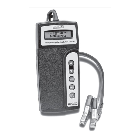
KEYPAD Use the ARROW buttons to scroll to menu choices. Use the ENTER button to make selections. Press the BACK button to move backwards to the previous step. Press the PRINT/VIEW button to enable print/view capability. IN-VEHICLE OR OUT-OF-VEHICLE TEST The analyzer will ask if the battery is connected in a vehicle or if it is out of a vehicle. -
Page 6: Rating Value
RATING VALUE At the prompt scroll to the battery’s rating value and press ENTER. ADDITIONAL TEST FEATURES SURFACE CHARGE REMOVAL If surface charge is detected while testing in the vehicle, the analyzer will prompt you to turn on the headlights to remove the surface charge. Follow the instructions on the display. -
Page 7: Starter System Test
NOTE: A REPLACE BATTERY result may mean a poor connection between the vehicle’s cables and the battery. After disconnecting the vehicle’s battery cables from the battery, retest the battery using the out- of-vehicle test before replacing. STARTER SYSTEM TEST IMPORTANT: When testing older model diesel engines in cold weather, preheating and post heating of the glow plug may skew test results. -
Page 8: Starter System Problems
STARTER SYSTEM PROBLEMS With the vehicle lights on If the engine does not crank and the lights dim heavily, check the con- nections to ensure the wiring is clean and in good condition. If the wiring is in good condition, repair or replace the starter. If the engine does not crank and the lights go out, there is probably a poor connection. -
Page 9: Charging System Test Results
Note: Some 8 cylinder vehicles and older vehicles idle at a high level after starting. This can allow the analyzer to detect a rev without any action being taken. If this occurs, continue on with the test process. The final test results will not be affected. Step 3: Testing at idle The Micro500 will analyze the charging system output at idle for compari- son to other readings. - Page 10 NO CHARGING VOLTAGE The alternator is not providing charging current to the battery. Check the belts to ensure the alternator is rotating with the engine running. If the belts are slipping or broken, replace the belts and retest. Check all connections to and from the alternator especially the connection to the battery.
-
Page 11: Voltmeter
EXCESS RIPPLE DETECTED One or more diodes in the alternator are not functioning or there is stator damage, which is shown by an excessive amount of AC or ripple current supplied to the battery. Check to ensure the alternator mounting is sturdy and that the belts are in good shape and functioning properly. -
Page 12: Print/View Capability
IR receiver at the bottom of the Midtronics printer (below the MODE button). With the printer on, align the IR output from the Micro500 with the receiver on the printer and press and hold the PRINT/VIEW button. -
Page 13: Troubleshooting
TROUBLESHOOTING DISPLAY PROBLEMS If the display does not illuminate • Check connection to the battery. • Battery may be too low to power the analyzer (below 1 volt). Fully charge the battery and retest. • Internal 9-volt battery may need to be replaced. Replace the 9-volt battery and retest. -
Page 14: Solutions
To turn the printer on, briefly press the MODE button. The green STATUS light should turn on. Make sure you are using the Midtronics printer provided with the Micro500. Other printers may not be compatible. - Page 15 REPLACING THE MICRO500 BATTERY The Micro500 uses a 9-volt battery to allow testing batteries down to 1 volt. When the battery requires replacing, the display shows “Low Internal Battery, Replace” when you connect to a battery. You should change the battery as soon after the message is displayed as possible.
- Page 16 PATENTS Made in the U.S.A. by Midtronics, Inc. and is protected by one or more of the following U.S. Patents: 6,469,511; 6,456,045; 6,445,158; 6,441,585; 6,392,414; 6,323,650; 6,316,914; 6,310,481; 6,304,087; 6,249,124; 6,225,808; 6,163,156; 6,091,245; 6,051,976; 5,831,435; 5,821,756; 5,757,192; 5,592,093; 5,585,728; 5,572,136; 4,912,416; 4,881,038; 4,825,170; 4,816,768; 4,322,685. Canadian Patents: 1,295,680;...
- Page 17 NOTES • •...
- Page 18 PN 168-100D 5/03 ©2003 Midtronics, Inc.
Need help?
Do you have a question about the PowerSensor Micro500 and is the answer not in the manual?
Questions and answers