Table of Contents
Advertisement
Quick Links
Advertisement
Table of Contents

Related Manuals for Ford 6.0L POWER STROKE


Summary of Contents for Ford 6.0L POWER STROKE
- Page 2 F O R W A R D This publication is intended to provide technicians and service personnel with an overview of technical advancements in the 6.0L POWER STROKE Diesel Engine. The information contained in this publication will supplement information contained in available service literature.
- Page 3 T h i s pa g e i n t e n t i o n a l l y l e ft b l a n k...
-
Page 4: Table Of Contents
6 . 0 L P O W E R S T R O K E TABLE OF CONTENTS O V E R V I E W ....... . . 6 Features . - Page 5 T h i s pa g e i n t e n t i o n a l l y l e ft b l a n k...
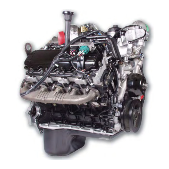
- Page 6 6.0L Power Stroke D i r e c t I n j e c t i o n Tu r b o c h a r g e d D i e s e l E n g i n e...
-
Page 7: Features
• Physical ID • Labeling Engine Features Engine Features • Variable Geometry Turbocharger • The 6.0L Power Stroke has been designed to meet the customers’ expectations of high • Digital Fuel Injection horsepower and torque over a wide RPM range. -
Page 8: Specifications
Firing Order ........1-2-7-3-4-5-6-8 Specifications Front • The 6.0L Power Stroke engine is a totally new engine design that will provide improved performance, and cleaner emissions. - Page 9 6 . 0 L P O W E R S T R O K E O V E R V I E W Engine Serial Number • The engine serial number is located on the left rear corner of the crankcase. •...
- Page 10 C O M P O N E N T L O C AT I O N S Front of Engine 1) Thermostat 2) Fuel Inlets on Cylinder Heads 3) Fuel Pressure Regulator 4) ECT Sensor 5) EGR Throttle Actuator (If Equipped) Left Front of Engine 1) Fuel Supply 2) Fuel Return...
- Page 11 C O M P O N E N T L O C AT I O N S Left of Engine 1) FICM 2) CMP Sensor 3) Oil Level Gauge 4) Crankcase Ventilation Left Rear of Engine 1) Rocker Arm Carrier 2) Bed Plate 3) Glow Plug Buss Bar...
- Page 12 C O M P O N E N T L O C AT I O N S Rear of Engine 1) Exhaust Expansion Joints 2) Heat Shields 3) Lifting “Eye” 4) Serial Number 5) ICP Sensor & IPR (Behind ICP) Right Rear of Engine 1) Block Heater 2) Turbine Outlet...
- Page 13 C O M P O N E N T L O C AT I O N S Right Side of Engine 1) CKP Sensor 2) Glow Plug Control Module Right Front of Engine 1) Heater Return 2) EGR Throttle Actuator...
- Page 14 C O M P O N E N T L O C AT I O N S Top of Engine 1) Oil Filter 2) Turbocharger Oil Supply Line 3) EVRT/VGT Control Valve 4) Injector Connectors 5) Secondary Fuel Filter 6) EGR Cooler Coolant Deaeration Port Top of Engine 1) EGR Valve 2) EGR Cooler...
-
Page 15: Identification
CYLINDER HEAD BOLTS Cylinder Head INTAKE VALVES INJECTOR NOZZLE • The 6.0L POWER STROKE uses a four (4) valve per cylinder head design to increase air flow and efficiency. • For identification, the exhaust valves are smaller than the intake valves. - Page 16 6 . 0 L P O W E R S T R O K E F E AT U R E S Dual Mass Flywheel STARTER RING • The 6.0L Power Stroke uses two different RING OF BOLTS flywheels for the manual transmission.
- Page 17 T h i s pa g e i n t e n t i o n a l l y l e ft b l a n k...
-
Page 18: System Flow
C O O L I N G S Y S T E M Cooling System Features Cooling System Features • The modular water pump can be serviced without disconnecting radiator hoses. • Both the glow plug sleeves and the injector •... - Page 19 C O O L I N G S Y S T E M Cooling System Flow: Front Cover • Coolant is drawn into the inlet of the front cover and then flows from the water pump through the front cover to the crankcase. •...
-
Page 20: Water Pump
RESERVOIR RESERVOIR object. Injector Sleeve • The 6.0L Power Stroke uses stainless steel injector sleeves to seal coolant from the injector and to transfer heat from the injector to the coolant. • The injector sleeve is replaceable. See unique service procedures or service manual for more details. - Page 21 C O O L I N G S Y S T E M Glow Plug Sleeve • Glow plug sleeves are used to keep coolant from coming in direct contact with the glow plugs and to seal coolant from the combustion chamber.
- Page 22 L U B R I C AT I O N S Y S T E M Lubrication System Features Lubrication System Features • The 6.0L Power Stroke uses an oil cooler that is mounted in the valley of the engine under the oil filter. There is also a oil •...
- Page 23 Oil Pan / Bed Plate WIDER OIL PAN • The 6.0L Power Stroke uses a two piece oil pan. The lower half is wider than the bottom of the engine to increase its capacity. Due to...
- Page 24 L U B R I C AT I O N S Y S T E M Pick-up Tube / Oil Aeration OIL PICK-UP TUBE OIL PICK-UP TUBE • The pick-up tube supplies oil from the oil pan to the oil pump. •...
-
Page 25: Oil Cooler
L U B R I C AT I O N S Y S T E M Front Cover • Oil flows from the crankcase to the oil pump ONE PIECE GASKET ONE PIECE GASKET via a passage in the back of the front cover. •... -
Page 26: Oil Temperature Sensor
ANTI DRAIN BACK change. OIL COOLER BYPASS Oil Filter • The 6.0L POWER STROKE uses a cartridge style oil filter, located on the top of the engine. OIL FILTER ELEMENT • When the oil filter is removed, the oil filter housing drain valve is automatically opened to drain most of the oil from the housing. - Page 27 L U B R I C AT I O N S Y S T E M Oil Flow at Oil Reservoir OIL FILTER DRAIN TO PAN OIL FEED TO OIL FEED TO • There are five (5) oil passages and one OIL COOLER OIL COOLER coolant passage near the oil reservoir in the...
- Page 28 • Secondary Fuel Filter during cool fuel conditions. • Fuel Check Valves • The 6.0L Power Stroke also has a secondary fuel filter. • There is a check valve in the front of each cylinder head that does not allow fuel to return to the fuel supply system.
- Page 29 F U E L S U P P LY S Y S T E M Engine Fuel Flow • After the fuel is conditioned by the past the fuel check valves. HFCM, the clean pressurized fuel is • The fuel pump, located in the sent to the secondary fuel filter •...
- Page 30 F U E L S U P P LY S Y S T E M HFCM (Horizontal Fuel Conditioning FUEL SUPPLY TO ENGINE FUEL SUPPLY TO ENGINE Module) FUEL RETURN TO TANK FUEL RETURN TO TANK • The HFCM is mounted to the frame rail on FUEL RETURN TO HFCM FUEL RETURN TO HFCM the drivers side.
-
Page 31: Check Valve
F U E L S U P P LY S Y S T E M Engine Mounted Fuel Filter SECONDARY FUEL FILTER SECONDARY FUEL FILTER • A secondary fuel filter is mounted to the oil filter housing. • The secondary filter is a 4 micron cartridge style filter. - Page 32 A I R M A N A G E M E N T S Y S T E M Air Management System Features Air Management System • The air management system is made up of Components/Features the air filter, turbocharger, charge air cooler, intake manifold, and the EGR system.
- Page 33 A I R M A N A G E M E N T S Y S T E M Control Valve System Flow • The CAC condenses the air by manifold has a passage that cooling it then the air returns to the connects it to the exhaust gas •...
- Page 34 A I R M A N A G E M E N T S Y S T E M Air Filter / Filter Minder FILTER MINDER FILTER MINDER • The air filter is located on the drivers side of the engine compartment between the battery and the radiator.
- Page 35 A I R M A N A G E M E N T S Y S T E M VGT Features VGT Turbocharger Features • The turbocharger for the 6.0L Power Stroke engine is designed to provide boost control at low and high speeds for improved throttle response.
- Page 36 A I R M A N A G E M E N T S Y S T E M VGT Control Valve OIL DRAIN TO PAN VGT COIL • The VGT control valve is commanded by the PCM, based on engine speed and load. The magnetic field generated by this signal OIL TO CLOSE SIDE moves a shaft in the control valve.
- Page 37 A I R M A N A G E M E N T S Y S T E M VGT Turbine Vanes Closed ACTUATOR PISTON • During engine operation at low engine UNISON RING speeds and load, little energy is available from the exhaust to generate boost.
- Page 38 A I R M A N A G E M E N T S Y S T E M EGR Valve • The PCM controlled EGR (Exhaust Gas Recirculation) valve adds cooled exhaust gases to the intake manifold to reduce NOx emissions.
- Page 39 A I R M A N A G E M E N T S Y S T E M EGR Throttle THROTTLE PLATE • All 2003.25 6.0L Power Stroke engines are equipped with a throttle body. • Some early versions also have a throttle plate in the throttle body.
- Page 40 F U E L M A N A G E M E N T S Y S T E M Generation II Fuel Management System Diagram • The generation II fuel management system uses high pressure oil and electronics to actuate and control fuel injection into the cylinders.
-
Page 41: High Pressure Oil System
F U E L M A N A G E M E N T S Y S T E M PUMP DISCHARGE LINE RESERVOIR HIGH PRESSURE CHECK VALVE STAND PIPE AND FITTING INJECTOR HIGH PRESSURE OIL RAIL HIGH PRESSURE PUMP GEAR HIGH PRESSURE PUMP HIGH PRESSURE OIL BRANCH... - Page 42 F U E L M A N A G E M E N T S Y S T E M High Pressure Oil System Schematic Oil Filter Oil Reservoir for High Pressure Filter Bypass Pump 0.95 Qt. 20 PSI Cooler Bypass High 25 PSI...
- Page 43 F U E L M A N A G E M E N T S Y S T E M High Pressure Pump & Cover DISCHARGE LINE • The high pressure pump is installed inside the crankcase. HIGH PRESSURE PUMP HIGH PRESSURE •...
-
Page 44: Fuel Injectors
F U E L M A N A G E M E N T S Y S T E M Fuel Injector Features Fuel Injector Features • The injector uses two (2) 48 volt 20 amp coils to control a spool valve that directs oil flow in and out of the injector. - Page 45 F U E L M A N A G E M E N T S Y S T E M Intensifier Piston • When the spool valve is in the open position, INTENSIFIER PISTON high pressure oil is allowed to enter the injector and pushes the intensifier piston and plunger downward.
-
Page 46: Stages Of Injection
F U E L M A N A G E M E N T S Y S T E M Stages of Injection Three Stages of Injection • The injection cycle has three (3) stages. • Fill. • Fill • Main injection. •... - Page 47 F U E L M A N A G E M E N T S Y S T E M Main Injection Step 1 • Pulse width controlled current energizes the open coil, magnetic force moves the spool valve to the open position. •...
- Page 48 F U E L M A N A G E M E N T S Y S T E M End of Main Injection Step 1 • When the IDM (Injector Drive Module) determines that the correct injector on time has been reached (meaning that the correct amount of fuel has been delivered), it sends a pulse width controlled current to the close...
- Page 49 T h i s pa g e i n t e n t i o n a l l y l e ft b l a n k...
-
Page 50: Sensors
E L E C T R I C A L C O M P O N E N T S Generation II Electrical Components Electrical Components Overview • The PCM uses information from the sensors to decide which commands to send to the FICM, the actuators, and the glow plug •... - Page 51 E L E C T R I C A L C O M P O N E N T S AP (Accelerator Pedal • The three-track pedal is a safety Position) feature. The three track pedal takes • The AP (Accelerator Pedal) is a the place of the Idle Validation three track pedal.
- Page 52 E L E C T R I C A L C O M P O N E N T S Baro (Barometric Pressure) • The BP sensor is a three (3) wire variable capacitance sensor. • The PCM supplies a 5 volt reference signal which the BP sensor uses to produce a linear analog voltage signal that indicates...
- Page 53 E L E C T R I C A L C O M P O N E N T S WIDE SLOT CKP (Crankshaft Position) end of the sensor. creates a signal the relates to crankshaft speed and position • The crankshaft position signal •...
- Page 54 E L E C T R I C A L C O M P O N E N T S CAMSHAFT TIMING PIN CMP (Camshaft Position) • Diagnostic information on the CMP PCM to the FICM so that the FICM input signal is obtained by can perform fueling calculations.
- Page 55 E L E C T R I C A L C O M P O N E N T S ECT (Engine Coolant Temp.) • When the temperature of the coolant increases, the resistance of the thermistor decreases and the •...
- Page 56 E L E C T R I C A L C O M P O N E N T S EGRVP (Exhaust Gas Recirculation Valve Position) • The EGRVP sensor is a three (3) wire potentiometer type sensor. • The PCM supplies a 5 volt reference voltage that the EGRVP uses to produce a linear analog voltage that indicates the amount of...
- Page 57 E L E C T R I C A L C O M P O N E N T S EOP (Engine Oil Pressure Switch) • The EOP (Engine Oil Pressure Switch) is a switch that closes a circuit to ground after engine oil pressure reaches approximately 5-7psi.
- Page 58 E L E C T R I C A L C O M P O N E N T S EOT (Engine Oil Temperature) changes in the operating environment, ensuring adequate • The EOT sensor is a two (2) wire power and torque are available for thermistor type sensor.
- Page 59 E L E C T R I C A L C O M P O N E N T S EP (Exhaust Pressure) • The EP sensor is a three (3) wire variable capacitance sensor. • The PCM supplies a 5 volt reference signal which the EP sensor uses to produce a linear analog voltage that indicates...
- Page 60 E L E C T R I C A L C O M P O N E N T S IAT1 (Intake Air Temperature sions. • The MAF/IAT1 sensor is mounted in • The Intake Air Temperature1 (IAT1) the intake air piping after the air sensor is a two wire thermistor filter.
- Page 61 E L E C T R I C A L C O M P O N E N T S IAT2 (Intake Air Temperature • The primary function of the IAT2 sensor is to provide a feedback signal to the PCM indicating •...
- Page 62 E L E C T R I C A L C O M P O N E N T S ICP (Injection Control monitors and adjusts for ideal ICP Pressure) determined by conditions such as load, speed, and temperature. • The ICP sensor is a three (3) wire •...
- Page 63 E L E C T R I C A L C O M P O N E N T S MAF (Mass Air Flow) • The Mass Air Flow (MAF) sensor uses a hot wire sensing element to measure the amount of air entering the engine.
- Page 64 E L E C T R I C A L C O M P O N E N T S MAP (Manifold Absolute Pressure) • The MAP sensor is a three (3) wire variable capacitance sensor. • The PCM uses the MAP sensor signal to assist in the calculation of EGR duty cycle.
-
Page 65: Actuators
• Actuators convert electrical output from the PCM to hydraulic, mechanical, or electronic work. • Injection Pressure Regulator (IPR) • The 6.0L Power Stroke uses four (4) actuators: Injection Pressure Regulator, • Exhaust Gas Recirculation Valve (EGR) Exhaust Gas Recirculation Valve, Variable Geometry Turbocharger Control Valve, and •... -
Page 66: Other Electrical Components
E L E C T R I C A L C O M P O N E N T S VGTCV (Variable Geometry VGT COIL Turbocharger Control Valve) CLOSE OPEN • The VGTCV (Variable Geometry Turbocharger Control Valve) is a duty cycle controlled valve that directs oil flow to the piston that controls the vanes in the turbocharger. - Page 67 E L E C T R I C A L C O M P O N E N T S PCM (Powertrain Control Module) • The Powertrain Control Module (PCM), which is mounted behind the battery on the drivers side inner fender panel, uses sensor inputs to control actuators and send fueling commands to the FICM.
- Page 68 E L E C T R I C A L C O M P O N E N T S Glow Plug • The glow plug is used to heat the air in the cylinder. • Inside the plug are two (2) coils (resistance) connected in series, one to create heat and one to control heat at its peak.
- Page 69 E L E C T R I C A L C O M P O N E N T S Glow Plug System Diagnostics • One way to verify diagnostic data from the GPCM is to measure the amperage draw INDUCTIVE with an inductive amp probe.
- Page 70 U N I Q U E S E R V I C E P R O C E D U R E S Oil Filter: Replacement OIL FILTER LID • First loosen the oil filter cap which will open the oil filter drain and allow the oil from the filter housing to drain into the crankcase.
- Page 71 U N I Q U E S E R V I C E P R O C E D U R E S Injector Removal: cont. • The injector connectors on the 6.0L Power Stroke are locked into the rocker arm carrier. •...
- Page 72 • Place the oil rail over the injectors and seat it by hand. The oil rail should then be tightened as specified. • Note: Anytime injectors are changed Ford lubricity additive should be added to the fuel filter and fuel tank.
- Page 73 U N I Q U E S E R V I C E P R O C E D U R E S Cylinder Head - Rocker Carrier: Removal • Before removing the rocker arm carrier the glow plug and injector connectors must be HEAD BOLTS HEAD BOLTS removed from the carrier.
- Page 74 U N I Q U E S E R V I C E P R O C E D U R E S Glow Plug / Injector Sleeve: Removal • Place the tap (part of tool #303-764) into the glow plug sleeve and cut threads into the sleeve.
- Page 75 • Note: Since the 6.0L POWER STROKE uses a closed crankcase ventilation system, it is normal to see oil carry over in the intake air system.
- Page 76 U N I Q U E S E R V I C E P R O C E D U R E S Turbocharger Oil Drain Tube: Removal TURBO MOUNTING TURBO OIL DRAIN • The turbocharger oil drain is located under TUBE PEDESTAL the turbocharger and is sealed with o-rings.
- Page 77 U N I Q U E S E R V I C E P R O C E D U R E S High Pressure Pump Cover: Removal HIGH PRESSURE HIGH PRESSURE PUMP COVER PUMP COVER • After removing the bolts that hold the high pressure pump cover to the crankcase, pull the cover straight up to disengage it from the high pressure pump discharge tube.
- Page 78 U N I Q U E S E R V I C E P R O C E D U R E S Front Cover: Gerotor Oil Pump • The lube oil pump is located to the front cover by dowels and sealed with a push in place gasket.
- Page 79 U N I Q U E S E R V I C E P R O C E D U R E S Crankshaft Rear Seal Dust Cover • There is a metal plate pressed onto the primary flange of the crankshaft. DUST SHIELD DUST SHIELD •...
- Page 80 G E N E R A L D I A G N O S T I C S Air in Fuel • Air in the fuel supply system can cause rough run, white smoke and low power. • To check for air in the fuel system, remove the return line (to tank from fuel pump module) from the fuel pump module.
- Page 81 G E N E R A L D I A G N O S T I C S ICP Pressure Low During Crank • If you have no (0 psi) ICP pressure during crank it could be the result of: major high pressure oil leak, lack of oil supply to the high pressure pump, bad high pressure pump, or the gear on the high pressure...
-
Page 82: Glow Plug
(Relative compression, Injector disable, actual compression, etc.). ALL INJECTORS ON Relative Compression Test • The relative compression test is now available for the 6.0L Power Stroke. #5 GLOW PLUG REMOVED • The relative compression test measures engine RPM during each compression stroke while cranking the engine. - Page 83 G E N E R A L D I A G N O S T I C S Crankcase Pressure Test • A new crankcase pressure orifice tool has been developed for the 6.0L Power Stroke. • The new tool has a smaller orifice in the top so that more accurate readings could be taken with the 0-60”...
- Page 84 A P P E N D I X T A B L E O F C O N T E N T S T o r q u e C h a r t s ......8 4 H a r d S t a r t / N o S t a r t D i a g n o s t i c s .
- Page 85 S P E C I A L T O R Q U E C H A R T COMPONENT STANDARD METRIC A i r i n l e t d u c t c l a m p ............4 4 l b f / i n 5 N m C a m s h a ft f o l l o w e r r e ta i n i n g d e v i c e b o l t .
- Page 86 S P E C I A L T O R Q U E C H A R T COMPONENT STANDARD METRIC L o w e r c r a n k c a s e o u t e r b o l ts ..........1 8 l b f / i n 2 4 N m O i l c o o l e r m o u n t i n g b o l ts ( M 8 ) .
- Page 87 S P E C I A L T O R Q U E C H A R T Intake Side Exhaust Side Figure A Cylinder Head Bolts • Step 1: Torque the M14 (1-10) cylinder head bolts to 65 lbf/ft (88 Nm) in the numerical sequence shown. •...
- Page 88 S P E C I A L T O R Q U E C H A R T High Pressure Oil Rail Bolts • Step 1: Install bolts 1, 2 and 3 finger tight. Figure C • Step 2: Press rail down until seated. •...
- Page 89 MODEL YEAR VEHICLE SERIAL N0.(VIN) CONDITION, IT IS NOT NECESSARY TO F-Series/Excursion Powerstroke 2003.25 COMPLETE THE REMAINDER OF THE 6.0L Power Stroke Diesel Engine Diagnostic Guide CHASSIS STYLE DIAGNOSTIC PROCEDURE. Customer Concerns (Please list in this box) DEALER NAME P & A...
- Page 90 MODEL YEAR VEHICLE SERIAL N0.(VIN) CONDITION, IT IS NOT NECESSARY TO F-Series/Excursion Powerstroke 2003.25 COMPLETE THE REMAINDER OF THE 6.0L Power Stroke Diesel Engine Diagnostic Guide CHASSIS STYLE DIAGNOSTIC PROCEDURE. Customer Concerns (Please list in this box) DEALER NAME P & A...
- Page 91 W I R I N G D I A G R A M ( S I N G L E A LT. )
- Page 92 W I R I N G D I A G R A M ( S I N G L E A LT. )
- Page 93 W I R I N G D I A G R A M ( D U A L A LT. )
- Page 94 W I R I N G D I A G R A M ( D U A L A LT. )
- Page 95 D I A G N O S T I C C O D E S * - MIL (Malfunction Indicator Light) Illuminates C - Continuous Operation O - Self Test - Key On Engine Off(KOEO) ^ - Tow/Haul Light flashes [] - Assigned but not used R - Self Test - Key On Engine Running(KOER) Condition Description...
- Page 96 D I A G N O S T I C C O D E S P0341 C* R Camshaft Position Sensor A Circuit CMP signal intermittent. Poor connection, defective sensor, electrical noise. Range/Performance (Bank 1 or single sensor) P0381 C* O Glow Plug/Heater Indicator Circuit Indicator Circuit Check - Instrument cluster driver checks for Open/Short circuit, lamp, fuse, PCM.
- Page 97 D I A G N O S T I C C O D E S P1703 O R Brake Switch Out Of Self Test Range P1705 O R Transmission Range Circuit Not Indicating Not in park during KOEO or KOER. Operator error, circuit failure, faulty sensor, PCM.
- Page 98 G L O S S A R Y A c t u a t o r D i g i ta l F u e l I n j e c t i o n A device which delivers motion in response to an electrical A fuel injection system that uses both an open and close signal.
- Page 99 G L O S S A R Y G l o w P l u g S l e e v e s L o n g L i f e E t h y l e n e G l y c o l C o o l a n t Stainless steel sleeves used to protect the glow plugs from A premium coolant, with an Ethylene Glycol base, that can be coolant.
- Page 100 G L O S S A R Y R o c k e r A r m C a r r i e r A housing that the rocker arms and their fulcrums are mounted to. T h e r m i s t o r Sensor used to determine temperature.
- Page 101 I N D E X Actuators, 64 Dual mass flywheel, 15 Air filter/ filter minder, 33 ECT (Engine Coolant Temperature), 54 Air in fuel, 79 Cooler, 37 Air management system Installation, 74 features, 31 Removal, 74 flow, 31-32 Flow, 37 Throttle, 38 Valve, 37-38 AP (Accelerator Pedal), 50...
- Page 102 I N D E X Fuel inlet check valves, 30 Injector Buzz, 82 I/O test, 80 Fuel pressure regulator, 30 Installation, 71 O-ring replacement, 70-71 Removal, 69-70 Fuel supply system Sleeve, 19 Features, 27 Installation, 73 Flow, 27-28 Removal, 73 Intake manifold, 38, 75 Generation II fuel management system advantages, 39...
- Page 103 I N D E X Rear Geartrain, 14 Relative compression test, 81 Rocker Arms, 72 Rocker carrier, 14 Removal, 72 Rocker fulcrums, 72 Sensors overview, 49 Single mass flywheel, 15 Specifications, 7 Stages of injection, 45 Table of contents, 3 Turbocharger Oil drain tube, 26 Removal, 75...
- Page 104 N O T E S...
- Page 105 N O T E S...
Need help?
Do you have a question about the 6.0L POWER STROKE and is the answer not in the manual?
Questions and answers