Table of Contents
Advertisement
Quick Links
Parts marked with "
" are important for maintaining the safety of the set. Be sure to replace these parts with
specified ones for maintaining the safety and performance of the set.
Installation MANUAL
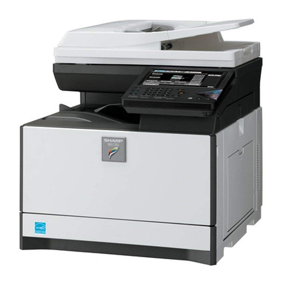
DIGITAL FULL COLOR
MULTIFUNCTIONAL SYSTEM
MODEL
SHARP CORPORATION
MX-C301/C301W
This document has been published to be used
for after sales service only.
The contents are subject to change without notice.
Advertisement
Table of Contents

Related Manuals for Sharp MX-C301


Summary of Contents for Sharp MX-C301
-
Page 1: Sharp Corporation
INSTALLATION MANUAL DIGITAL FULL COLOR MULTIFUNCTIONAL SYSTEM MX-C301/C301W MODEL Parts marked with " " are important for maintaining the safety of the set. Be sure to replace these parts with specified ones for maintaining the safety and performance of the set. - Page 2 Machine Environment, Installation and Transportation 1.Machine Environment and Installation (2)Power voltage Measure the voltage during copying to check that the voltage is in the Before installing the machine, check that the following conditions are range of the specified voltage +/- 10%. satisfied.
-
Page 3: Transit And Delivery
Operational environment If these items are neglected, a trouble may be generated in the copy and print image quality. Temperature: 10 to 35 degree C Humidity: 20 to 85% RH 2.Transit and delivery Atmospheric pressure: 590 to 1013hPa (altitude: 0 to 2000 m) Content Method (2)Contaminates... - Page 4 120V (USA) Operation Manual 1 set Ferrite core 2.Installation A.Remove the cap from developing unit 1) Remove the tray. * Be sure not to hold the scanner unit to lift up the main unit. MX-C301 MX-C301/C301W(MAIN UNIT) 2 – 1...
- Page 5 NOTE: Press the center of the cartridge until it is locked when installing the cartridge. Black Magenta Cyan Yellow NOTE: Be sure to keep the caps. Caps are used when the machine is transferred to the different location. MX-C301 MX-C301/C301W(MAIN UNIT) 2 – 2...
- Page 6 When connecting the line cable (to LINE or TEL), wind the line cable two turns around the included ferrite core as shown in the fig- ure, and connect to the modular jack which is marked with “LINE.” Insert the tray slowly. MX-C301 MX-C301/C301W(MAIN UNIT) 2 – 3...
-
Page 7: Image Quality Check
[EXECUTE] key. - Printing quality ; SIM64-5 When the result of the print quality is not good, perform [ADJ10] by referring the [5] ADJUSTMENT of the Service Manual. Successfully Finished Error occurs MX-C301 MX-C301/C301W(MAIN UNIT) 2 – 4...
Need help?
Do you have a question about the MX-C301 and is the answer not in the manual?
Questions and answers