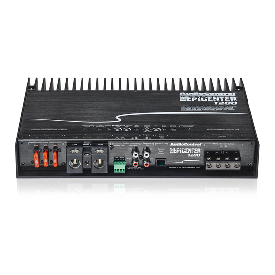
AudioControl Epicenter 600 Installation Manual

AudioControl Epicenter 600 Installation Manual

High-power subwoofer amplifiers

Advertisement

Quick Links

AND
HIGH-POWER SUBWOOFER AMPLIFIERS
Installation Manual

Advertisement

Table of Contents
loading
Need help?

Need help?

Do you have a question about the Epicenter 600 and is the answer not in the manual?

Questions and answers

Summary of Contents for AudioControl Epicenter 600

  • Page 1 HIGH-POWER SUBWOOFER AMPLIFIERS Installation Manual...
  • Page 2: Important Safety Instructions

    10. Provide +12V and Ground wiring of sufficient size to ensure adequate remove the top panel to access the controls. current to the amplifier. For the Epicenter 600 / 1200 this means 4 gauge There are no user-serviceable parts inside. Refer wire or lower.
  • Page 3: Table Of Contents

    Speaker and Wiring Impedance ....... .17 ©2015 AudioControl Inc All rights reserved.
  • Page 4: Chapter 1: Introduction

    The Epicenter amplifier is not a cold heartless box for increasing The Epicenter amplifiers are designed by AudioControl, the only elec- the loudness of bass frequencies in your system. It restores the bass tronics company in the world that specializes in amplifiers, equalizers, frequencies to how they were meant to be.
  • Page 5: Features

    Features MILC™ Maximum Input Level Control • Here are some of the features that make the Epicenter 600 and 1200 The Epicenter amplifier analyses the incoming audio signals and amplifiers very unique and unlike any other amplifiers: detects any signal clipping. This gives you the chance to optimize •...
  • Page 6: Complimentary Bullet Points

    • Class D Monoblock Subwoofer Amplifier • High Current Design - 1 Ohm Stable • 600 Watts @ 1 Ohm (The Epicenter 600 Amplifier) • 1200 Watts @ 1 Ohm (The Epicenter 1200 Amplifier) • The Epicenter Digital Bass Restoration •...
  • Page 7: Chapter 2: Quick Start Guide

    10 11 12 19 20 Remote Control Connector 17. Polarity Note: The Epicenter 1200 is shown. The Epicenter 600 has the same Speaker-Level Outputs controls and features, except for two fuses, and different power termi- 18. Expansion Bus Mode nals and speaker-level output terminals.
  • Page 8: Quick Start

    Chapter 2: Quick Start Guide Quick Start 1. It only takes a few steps to get your Epicenter amplifier up and 8. Connect your audio inputs to the unit – either speaker-level or running in a flash! The steps below are explained in more detail line-level RCA…...
  • Page 9: Chapter 3: Hookup Diagrams

    Chapter 3: Hookup Diagrams Power Connections In this example, the head unit has a +12V trigger Head Unit output that is connected to the Epicenter’s remote input terminal. When the head unit is turned on, it will turn on the Epicenter amplifier. Alternatively, the GTO signal sense feature can be Remote Amplifier used to gently turn on the Epicenter amplifier when...
  • Page 10: System #1

    Chapter 3: Hookup Diagrams System #1: Adding Subwoofers to a Factory Radio Factory Speaker-level Radio output ACR-3 Subwoofers Installation Manual...
  • Page 11: System #2

    Chapter 3: Hookup Diagrams System #2: Using the Expansion Bus to run multiple Amplifiers, linked to one Master set of Controls Factory Speaker-level Radio output Expansion Bus Expansion Bus Mode: Source Mode: Link ACR-3 Master Left Right Subwoofer Subwoofer...
  • Page 12: System #3

    Chapter 3: Hookup Diagrams System #3: Using the Expansion Bus to run two Amplifiers to double the power into one Subwoofer Factory Radio Speaker 0˚ 180˚ level Source Link output ACR-3 Master Subwoofer Note: In this example, the subwoofer impedance should not be less than 2 Ohms Installation Manual...
  • Page 13: Chapter 4: Installation

    Chapter 4: Installation Installation 5. Always mount the amplifier as far from the antenna in the ve- hicle as possible. At the same time you will want to install your amplifier away from the radio or any other RF sensitive electron- We recommend mounting the Epicenter amplifier in the trunk/boot ics in the vehicle.
  • Page 14 AudioControl DQDX!! (Shameless plug). There are generally only two things to consider when using the line-level RCA inputs: 1.
  • Page 15: Acr-3 Dash Control Installation

    Chapter 4: Installation ACR-3 Dash Control Installation The AudioControl ACR-3 dash control is a dual-function remote for your Epicenter amplifier. It may be mounted under the dash using its own bracket, or through a custom hole in the dash. The endless knob should be within reach of the driver, and in a spot where the two LEDs 1.
  • Page 16: Top Lid Removal And Installation

    Chapter 4: Installation Top Lid Removal and Installation Re-installation Procedure The top lid must be removed to gain access to the controls, and then put back on again to protect the controls from dust bunnies, food 1. Ensure that the two M3 x 10 mm screws on the straight edge of crumbs, and other dirt and grime.
  • Page 17: Speaker Connections

    Chapter 4: Installation Speaker Connections Establish a standard connection color code and stick with it. One Often the real world is more complicated than theory, and for speak- conductor of the speaker wire is normally marked by a different color ers this is the case.
  • Page 18: Chapter 5: Features

    Connection Panel Features 2 3 4 1. Fuses 40A – There are two fuses on Epicenter 600, and three on 3. Remote Power Input Terminal – This screw terminal connects the Epicenter 1200 as shown. Replace the fuses only with the to the 12V remote trigger output of some head units.
  • Page 19 Make sure that the average combined speaker impedance does not dip below 1 Ohm. The Epicenter 600 has two connections (plus and minus) and the Epicenter 1200 has two of each (two...
  • Page 20: Control Panel Features

    Chapter 5: Features Control Panel Features 10 11 12 19 20 Installation Manual...
  • Page 21 Chapter 5: Features 10. Power LED – If you have connected your battery power, vehicle If the protection LED should come on, read the red codes quickly ground, and turn-on lead (or GTO signal sensing) correctly, then before turning off the system and investigating. Shorts, like this light should be green to indicate the power is ON.
  • Page 22 The net result is The music: how it was recorded AND how it is being played back wasted amplifier power and damaged speakers. The AudioControl Speakers and speaker enclosures PFM filter is a programmable subsonic filter that allows the speak- Because of the variations in the recording process, we developed er to play only as low as it should be playing.
  • Page 23 Chapter 5: Features 16. Gain Control – This control allows you to adjust the overall 19. Source Clip LED – The Epicenter amplifier features our MILC™ volume output level in the normal way, with counterclockwise (Maximum Input Level Control) patent-pending level-setting cir- decreasing the volume, and clockwise increasing.
  • Page 24: Chapter 6: Adjusting The System

    Chapter 6: Adjusting The System Adjusting the System If you have ever listened to a friend’s “Killer” car audio system and volume music in the region of interest. This is a subwoofer am- were sad to hear lots of hiss, clicks, or pops, then you have experi- plifier, so the region of interest is 20 Hz to 200 Hz. ...
  • Page 25: Chapter 7: Troubleshooting

    Many problems can be eliminated by re-checking the wiring and settings of the unit. If a problem cannot be solved using the guide Power (Blue) Codes below, please call the AudioControl team for further assistance, or Power Up e-mail us at sound.great@audiocontrol.com Reset Boot 1.
  • Page 26 Chapter 7: Troubleshooting 3. Source Clip LED is on: 6. Should I notice a blue glow coming from within the unit, near the heat- a. Turn down the level of the audio signals entering the Epicen- sinks? ter. The Epicenter analyses the incoming audio and detects if the signal is clipping.
  • Page 27: Chapter 8: Specifications

    Chapter 8: Specifications Specifications All specifications are measured at 14.4 VDC (standard automotive voltage). As technology advances, AudioControl reserves the right to continuously change our specifications, like our Pacific Northwest weather, although we are working on changing that as well.
  • Page 28: Block Diagram

    Chapter 8: Specifications Block Diagram Left Speaker Level to Line Level MILC Right Conversion Source Clip Detect Left Balanced Polarity POWER AMP Summing Subsonic 1200 W Mixer 1 Ohm Min Right Sweep Variable Expansion Bus Gain Wide Signal Sense Crossover Mode Source Link...
  • Page 29: Dimensions

    Chapter 8: Specifications The Epicenter 1200 Dimensions...
  • Page 30 Chapter 8: Specifications The Epicenter 600 Dimensions Installation Manual...
  • Page 31: Chapter 9: Service

    Phone 425-775-8461 3. A return street address. (No PO Boxes, please). FAX 425-778-3166 4. A daytime phone number in case our technicians have a ques- tion about the problem you are having, or if they are just feeling e-mail: sound.great@audiocontrol.com lonely.
  • Page 32: Chapter 10: Please Remain Calm

    People are confused by warranties! Lots of fine print. Months of wait- product, the warranty is five years, otherwise the warranty is ing around. Well, fear no more AudioControl is here. Our warranty is limited to one year. designed to make you rave about AudioControl. It’s a warranty that looks out for our customers, plus helps you resist the temptation to 4.
  • Page 33: Legalese Section

    Chapter 10: Please Remain Calm Legalese Section This is the only warranty issued by AudioControl. This warranty gives you specific legal rights, and you may also have rights that vary from state to state. Promises of how well your AudioControl product will work are not implied by this warranty.
  • Page 34: Chapter 11: Complementary Doodle Pages

    Chapter 11: Complementary Doodle Pages Favorite Settings System System System Installation Manual...
  • Page 35 Chapter 11: Complementary Doodle Pages System System System...
  • Page 36 The End Installation Manual PN 913-134-0 Rev A...

This manual is also suitable for:

Epicenter 1200

Table of Contents