Table of Contents
Advertisement
Quick Links
W A R N I N G
If the information in these instructions are not followed
exactly, a fire or explosion may result causing property
damage, personal injury or loss of life.
Do not store or use gasoline or other flammable
vapors and liquids in the vicinity of this or any
other appliance.
WHAT TO DO IF YOU SMELL GAS:
Do not try to light any appliance.
Do not touch any electrical switch; do not use
any phone in your building.
Immediately call your gas supplier from a
neighbor's phone. Follow the gas supplier's
instructions.
If you cannot reach your gas supplier, call the
fire department.
Installation and service must be performed by a
qualified installer, service agency or the gas
supplier.
INSTALLER: Leave this manual with the appliance.
CONSUMER: Retain this manual for future reference.
Gas Fired Vented Room
U
M
This appliance may be installed in an aftermarket
permanently located, manufactured home (USA only) or
mobile home, where not prohibited by local codes.
This appliance is only for use with the type
of gas indicated on the rating plate. This appliance is
not convertible for use with other gases, unless a
certified kit is used.
*Conversion kit required for Propane use
7116 Beatty Dr
Mission, BC V2V 6B4
Canada
31-DVIE33C
Heater (Direct Vent)
S/N 211061And up
I
SERS'
NSTALLATION
O
PERATION and
AINTENANCE
Tested and
listed by
LABTEST Certification Inc
Richmond, British Columbia
ANSI Z21.88-2009/CSA 2.33-2009
M
ANUAL
200-1131
MAY 2014
Advertisement
Table of Contents

Subscribe to Our Youtube Channel
Related Manuals for Archgard 31-DVIE33C


Summary of Contents for Archgard 31-DVIE33C
- Page 1 31-DVIE33C Gas Fired Vented Room Heater (Direct Vent) S/N 211061And up SERS’ NSTALLATION PERATION and AINTENANCE ANUAL This appliance may be installed in an aftermarket W A R N I N G permanently located, manufactured home (USA only) or mobile home, where not prohibited by local codes.
- Page 2 31-DVIE33C STATE OF MASSACHUSETTS REQUIREMENTS 5.08: Modifications to NFPA-54, Chapter 10 (2) Revise 10.8.3 by adding the following additional requirements: (a) For all side wall horizontally vented gas fueled equipment installed in every dwelling, building or structure used in whole or in part...
-
Page 3: Table Of Contents
31-DVIE33C TABLE OF CONTENTS Caution and Safety Instructions Appliance Certification, Installation Codes and Specifications Rating Plate Control Panel Locations & Appliance Dimensions Minimum Fireplace Opening Dimensions, Sealing the Vent Factory Built (metal) Fireplace Requirements 10-11 Mantle and Sidewall Clearances Gas Connections... - Page 4 Congratulations on choosing an Archgard Gas Fireplace! The 31-DVIE33C is one of the most advanced Direct Vent Insert heaters available today. It is solidly designed using the latest technology and manufactured to the highest quality. It is our aim to provide you with an appliance for many trouble-free years of reliable service.
-
Page 5: Caution And Safety Instructions
Y O U R S A F E T Y Do not install or operate your Archgard 31-DVIE33C without reading and understanding this manual. Any installation or operational deviation from this instruction manual voids the Archgard Industries Warranty and may prove hazardous. -
Page 6: Appliance Certification, Installation Codes And Specifications
The listing label is attached to the appliance on the bottom right side of the appliance. A copy is shown on page 7 Please contact Archgard Industries Ltd., if you have any questions regarding the certification of this appliance. INSTALLATION CODES This appliance must be installed by a qualified gas appliance installer. -
Page 7: Rating Plate
31-DVIE33C RATING PLATE We recommend that our gas hearth products be installed and serviced by professionals who are certified in the U.S. by the National Fireplace Institute® (NFI) as NFI Gas Specialists. -
Page 8: Control Panel Locations & Appliance Dimensions
31-DVIE33C CONFIGURE THE FIREPLACE - CONTROL PANEL LOCATIONS The control panels can be mounted in the following different ways. They are shipped in the “Controls In” configuration. They can be moved to the “Controls Out” configuration by removing the two mounting screw on each side and swinging the panels out and replacing the screws. -
Page 9: Minimum Fireplace Opening Dimensions, Sealing The Vent
31-DVIE33C MINIMUM FIREPLACE OPENING DIMENSIONS Masonry Fireplace Min flue size required TOP VIEW SIDE VIEW 4” (102) x 7” (178) Fig. 9-B Fig. 9-A DIMENSIONS 20-1/4” 14” 19” 30” 0” “Controls Out” (514 mm) (356 mm) (483 mm) (762 mm) DIMENSIONS 20-1/4”... -
Page 10: Factory Built (Metal) Fireplace Requirements
31-DVIE33C Factory –Built (metal) Wood-Burning Fireplace Opening Requirements Fig. 10-A I N S T A L L E R N O T E S The installer must mechanically attach a marking (supplied in the manual bag) to the inside of the firebox of the... - Page 11 31-DVIE33C W A R N I N G Failure to position the parts in accordance with these diagrams or failure to use only parts specifically approved with this appliance may result in property damage or personal injury. W A R N I N G Any hearth extending out in front of the insert must not have any portion above 7”...
-
Page 12: Mantle And Sidewall Clearances
31-DVIE33C MANTLE CLEARANCES W A R N I N G Failure to position the parts in accordance with these diagrams or failure to use only parts specifically approved with this appliance may result in property damage or personal injury. Fig. 12-A... -
Page 13: Gas Connections
31-DVIE33C GAS CONNECTIONS Before connecting the appliance to the gas supply line, double check that the appliance you have purchased is designed for the gas type you are using. The gas type markings are located on the certification label and also on the appliance’s gas valve. -
Page 14: Conversion Kit Instructions
31-DVIE33C CONVERSION KIT INSTRUCTIONS W A R N I N G This conversion kit shall be installed by a qualified service agency in accordance with the manufacturers instructions and all applicable codes and requirements of the authority having jurisdiction. If the information in these instructions is not followed exactly, a fire, explo- sion or productions of carbon monoxide may result, causing property damage, personal injury or loss of life. -
Page 15: Conversion Kit Instructions
31-DVIE33C CONVERSION KIT INSTRUCTIONS, cont. CONVERT THE GAS VALVE COMPLETE THE CONVERSION Turn on the gas and electrical supplies. Turn on the fireplace so the burner is on Check for leaks at all connections. Test inlet and outlet pressure. Visually check pilot flame. Flame should envelope top of the flame sensor and extend forward onto the burner. -
Page 16: Appliance Description, Leveling The Appliance And Electrical Requirements
ELECTRICAL CONNECTIONS The 31-DVIE33C comes complete with an adjustable speed fan with 6 levels wired directly to the main control module for your protection against shock hazard. Do not cut or remove the grounding prong from this plug. -
Page 17: Venting Instructions
3” (76 mm) inside bend radius. The 31-DVIE33C showing the Fresh Air Intake and The Air Intake Flex Liner must be connected to the inlet air Exhaust locations. - Page 18 31-DVIE33C VENTING INSTRUCTIONS 999-INS-TK Instructions for use with Archgard vertical termination cap. Part # 999-INS-TK Install the termination cap being sure to provide sufficient space (around and on top) so as not to impede the flow of air, both into and out of the cap. This cap is only to be used for non combustible installations. Do not recess into the top of the chim- ney.
-
Page 19: Restrictor Plate, Surround Installation And Rocker Switch Wiring
31-DVIE33C VENT RESTRICTOR INSTALLATION When the vent is over 18’(5.5m) a vent restrictor may be required. The installation of the restrictor will equalize the vent stack action that can cause problems with a proper fire set-up. The vent restrictor is supplied loose in the manual bag. When required, it installs onto the upper baffle in the center portion. -
Page 20: Fire Bead Installation
31-DVIE33C Fire Bead Installation Fig. 20-A W A R N I N G Failure to position the parts in accordance with these diagrams or failure to use only parts specifically approved with this appliance may result in property damage or personal injury. -
Page 21: River Rock Installation
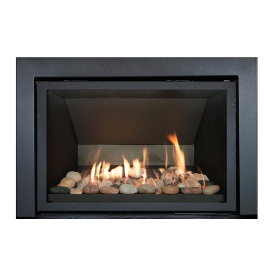
31-DVIE33C River Rock Installation Shown with 31-SKHSBS Surround Fig. 21-A Fig. 21-B Fig. 21-C Distribute the rocks evenly around the burner to personal preference. Care must be taken that you DO NOT cover burner ports with any of the “large” stone flat surfaces. Keep burner ports clear of blockage: ie flat sur- faces of the rocks to create an enjoyable burning fire. -
Page 22: Glass Door Removal / If Your Glass Should Break
Do not operate appliance with the glass front cracked or broken. Replacement of the glass should be done by a licensed or qualified service person. IF YOUR GLASS BREAKS In the event your glass cracks or breaks, Archgard recommends that a new door assembly be ordered to re- place the original door. ... -
Page 23: Final Installation Check And Initial Operation
31-DVIE33C FINAL INSTALLATION CHECK Each Archgard Gas Fireplace is checked and tested at the factory prior to being packaged and shipped to our dealers and finally installed in your home. Archgard recommends that before leaving this unit with the customer, the installer must ensure that the appliance is firing correctly and that the electrical system is in working order. -
Page 24: First Fire And Lighting Instructions (Caution)
31-DVIE33C FIRST FIRE A T T E N T I O N When operated for the first few times, the appliance will emit some odor and fumes. This is due to the heat evaporating the oils and solvents used in the production of the fireplace. -
Page 25: Ignition Sequence
31-DVIE33C SIT INTERMITTENT IGNITION SEQUENCE Fig. 25-A... -
Page 26: Lighting Instructions On Rating Plate
31-DVIE33C LIGHTING INSTRUCTIONS ON RATING PLATE... -
Page 27: Remote Control Setup And Operation
31-DVIE33C REMOTE CONTROL SETUP AND OPERATION I M P O R T A N T The Proflame II Transmitter is an integrated part of the Proflame II System, which consists of these elements: Proflame II Transmitter, to be used in conjunction with: ... - Page 28 31-DVIE33C REMOTE CONTROL SETUP AND OPERATION HANDHELD REMOTE DISPLAY (future option) N/A on this unit Fig. 28-A W A R N I N G THE TRANSMITTER AND RECEIVER ARE RADIO FREQUENCY DEVICES. PLACING THE TRANSMITTER IN OR MEAR METAL ENCLOSURES MAY RE-...
- Page 29 31-DVIE33C REMOTE CONTROL SETUP AND OPERATION INITIALIZING THE SYSTEM FOR HANDHELD REMOTE OPERATION Connect IFC Control Module to AC power supply. A single “beep” will indicate the presence of power. NOTE: This will initiate Pilot Start-up in Manual Mode. The pilot will spark repeatedly and ignite if gas has been supplied to the unit if the main power switch is in the “ON”...
- Page 30 31-DVIE33C REMOTE CONTROL SETUP AND OPERATION TEMPERATURE INDICATION DISPLAY With the system in the “OFF” position, press the Thermostat Key and the Mode Key at the same time to switch between Fahrenheit (F) or Celsius (C). Verify on the LCD screen the correct designation is visible...
- Page 31 31-DVIE33C REMOTE CONTROL SETUP AND OPERATION ROOM THERMOSTAT (TRANSMITTER OPERATION) The Remote Control can operate as a room thermostat. The thermostat can be set to a desired temperature to control the comfort level in a room. To activate this function: ...
- Page 32 31-DVIE33C REMOTE CONTROL SETUP AND OPERATION Continuous Pilot/Intermittent Pilot (CPI/IPI) selection With the system in “OFF” position press the Mode Key to index to the CPI mode icon. Pressing the UP Arrow Key will activate the Continuous Pilot Ignition mode (CPI). Pressing the Down Arrow Key will return to IPI. A single “beep”...
-
Page 33: Remote Control Setup And Operation
31-DVIE33C REMOTE CONTROL SETUP AND OPERATION KEY LOCK This function will lock the keys to avoid unsupervised operation. To activate this function, press the MODE and UP Keys at the same time. To deactivate this function, press the MODE and UP Keys at the same time. -
Page 34: Maintenance And Cleaning The Appliance
Regularly: Frequent cleaning of the ceramic glass is required. Archgard recommends using a good quality “gas fireplace” glass cleaner that is available at any hearth retail location. DO NOT CLEAN WHILE HOT. -
Page 35: Servicing Under Warranty And Adjusting Primary Air
31-DVIE33C SERVICING UNDER WARRANTY Before servicing, read the terms and conditions of the Archgard warranty at the back of the manual. Contact the authorized Archgard dealer where you purchased the appliance from and provide them with details of the problem, along with the initial installation information (from the front of this manual). -
Page 36: Checking Inlet/Outlet Gas Pressures, Adjusting Pilot And Convertible Pilot Orifice
31-DVIE33C CHECKING INLET AND OUTLET GAS PRESSURE 1. Remove the surround. 2. The pressure test taps are located on the valve. The taps are located in the gas valve front face. The inlet is marked ‘IN’ and the outlet is marked ‘OUT’. See Fig.1. -
Page 37: Replacing Comfort Blower
31-DVIE33C REPLACING COMFORT BLOWER C A U T I O N Label all wires prior to disconnection when servicing controls. Wiring errors can cause improper and dangerous operation. Verify proper operation after servicing This appliance, when installed, must be electrically grounded in accordance with local codes or, in the absence of local codes, with the National Electrical Code, ANSI/NFPA 70, or the Canadian Electrical code, CSA C22.1. -
Page 38: Wiring Schematic
31-DVIE33C WIRING SCHEMATICS Synchronization button Fig. 38-A Main On/Off switch must be connected to the surround switch and in the “on” position for the remote to operate the fireplace... -
Page 39: Warranty
Problem Description ❖ NOTE: Warranty may be void if work is carried out by an unqualified person (s). Only original Archgard parts may be used. Please consult your Archgard dealer or representative if in doubt about a replacement part (s). -
Page 40: Frequently Asked Questions
Q. My fan/blower makes a “whirring” or “humming” noise. A. Your Archgard gas appliance uses a powerful fan to push heated air into your room. It is not un- usual to hear a “humming” noise when your fan is running. Note: the sound will change depending on the setting that your fan speed control is set at. -
Page 41: Replacement Parts List
31-DVIE33C REPLACEMENT PARTS LIST - ARCHGARD 31-DVIE33C Item # Item Description Unit 308-6011 SIT Pro Flame II Electronic Control Module 308-6014 SIT Pro Flame II Handheld Transmitter 308-6017 SIT 885 Gas Valve c/w Step Motor 305-6002 Module Main Wiring Harness (5 wire) -
Page 42: Notes
31-DVIE33C NOTES... -
Page 43: Warranty Registration
WARRANTY REGISTRATION RCHGARD NDUSTRIES 7116 BEATTY DRIVE MISSION, B.C. CANADA V2V 6B4 FOLD DOWN AT LINE FOLD DOWN AT LINE & TAPE CLOSED 31-DVIE33C Model # : Serial #: Date Installed: ______/________/__________ yyyy Name: Address: _________________________________________ City: ___________ State/Prov: ZIP: _________ Phone: ( _____ ) ________-__________ Dealer's Name &... - Page 44 Archgard Industries Ltd. 7116 Beatty Drive Mission, B.C. V2V 6B4 Canada Website: www.archgard.com...
Need help?
Do you have a question about the 31-DVIE33C and is the answer not in the manual?
Questions and answers