Avocent DSR-1021 Installer/User Manual
Avocent dsr-1021; dsr-1022 switch
Hide thumbs
Also See for DSR-1021:
- Installer/user manual (110 pages) ,
- Quick installation manual (2 pages) ,
- Release note (2 pages)
Table of Contents
Advertisement
Quick Links
Download this manual
See also:
Installer/user Manual
Advertisement
Table of Contents

Related Manuals for Avocent DSR-1021


Summary of Contents for Avocent DSR-1021
- Page 1 ® 1021/1022 Switch Installer/User Guide Avocent, the Avocent logo, The Power of Being There, DSR, DSView and OSCAR are registered trademarks of Avocent Corporation or its affiliates. All other marks are the property of their respective owners. © 2004 Avocent Corporation. All rights reserved.
- Page 2 USA Notification Warning: Changes or modifications to this unit not expressly approved by the party responsible for compliance could void the user’s authority to operate the equipment. Note: This equipment has been tested and found to comply with the limits for a Class A digital device, pursuant to Part 15 of the FCC Rules.
-
Page 3: Table Of Contents
T A B L E O F C ON T E N T S List of Figures ........................v List of Tables ........................vii Chapter 1: Product Overview..................1 Features and Benefits ......................... 1 Safety Precautions ........................4 Chapter 2: Installation ..................... 5 Installation Overview........................ - Page 4 DSR1021/1022 Switch Installer/User Guide...
-
Page 5: List Of Figures
LIST OF FIGURES Figure 1.1: Example DSR1021/1022 Switch Configuration ............. 3 Figure 1.2: The DSR1021 Switch ...................... 3 Figure 1.3: The DSR1022 Switch ...................... 4 Figure 2.1: Basic DSR1021 Switch Configuration................6 Figure 3.1: Main Dialog Box ......................13 Figure 3.2: Setup Dialog Box ......................18 Figure 3.3: Names Dialog Box ...................... - Page 6 DSR1021/1022 Switch Installer/User Guide...
-
Page 7: List Of Tables
LIST OF TABLES Table 3.1: OSCAR Interface Status Symbols ................... 14 Table 3.2: OSCAR Interface Navigation Basics ................15 Table 3.3: Setup Features to Configure the OSCAR Interface............17 Table 3.4: OSCAR Interface Status Flags ..................24 Table 3.5: Commands to Manage Routine Tasks for Your Target Device(s)........33 Table C.1: DSRIQ-SRL Module Pinouts .................. - Page 8 viii DSR1021/1022 Switch Installer/User Guide...
-
Page 9: Chapter 1: Product Overview
Product Overview Features and Benefits ® Avocent DSR switches combine analog and digital technology to provide flexible, centralized control of data center servers and facilitate the OA&M (operations, activation and maintenance) of remote branch offices where trained operators may be unavailable. They provide enterprise customers with a significant reduction of cable volume, secure remote access and flexible server management from anywhere at anytime. -
Page 10: Simple Access To Any Target Device
DSR1021/1022 Switch Installer/User Guide The DSRIQ-SRL (serial) module is a DCE device that provides the primary interface between a serial device and a DSR1021/1022 switch. It provides VT100 terminal emulation, break suppression and port history in a compact, convenient module. Access the DSR1021/1022 switch via network connection No special software or drivers are required on the attached, or client, computers. -
Page 11: Figure 1.1: Example Dsr1021/1022 Switch Configuration
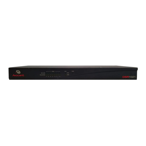
Chapter 1: Product Overview DSR Switch Ethernet DSView Server Software Modem Telephone Network Analog User (OSCAR Graphical Digital User User Interface) (Computer with Internet browser) Figure 1.1: Example DSR1021/1022 Switch Configuration DSR1021 Switch Number of target devices Digital paths Analog user Figure 1.2: The DSR1021 Switch... -
Page 12: Safety Precautions
To avoid potentially fatal shock hazard and possible damage to equipment, please observe the following precautions: • Do not use a 2-wire power cord in any Avocent product configuration. • Test AC outlets at the target device and monitor for proper polarity and grounding. -
Page 13: Chapter 2: Installation
The DSR1021/1022 switch uses TCP/IP for communication over Ethernet. Although 10BaseT Ethernet may be used, Avocent recommends a dedicated, switched 100BaseT network. The DSR1021/1022 switch uses the Point-to-Point Protocol (PPP) for communication over a V.34, V.90 or V.92 modem. -
Page 14: Figure 2.1: Basic Dsr1021 Switch Configuration
DSR1021/1022 Switch Installer/User Guide The following diagram illustrates one possible configuration for your DSR1021/1022 switch. Digital User Ethernet Telephone Power Network Cord Internet Connection Ethernet and/or Modem DSR1021 Switch Ports SETUP Port CAT 5 Cable SPC Port Connection Analog User Connections Power Control Server... -
Page 15: Setting Up Your Network
The DSR1021/1022 switch supports both Dynamic Host Configuration Protocol (DHCP) and static IP addressing. Avocent recommends that IP addresses be reserved for each switch and that they remain static while the DSR switches are connected to the network. For additional information on setting up the DSR switch using the DSView Server software, and for information on how the DSR switch uses TCP/IP, see the DSView Installer/User Guide. -
Page 16: Connecting The Dsr Switch Hardware
DSR1021/1022 Switch Installer/User Guide Connecting the DSR Switch Hardware NOTE: The DSR1021/1022 switch may be rack mounted in a 1U configuration. The DSR1021/1022 switch does not support a 0U configuration. To connect and power up your DSR1021/1022 switch: Power down the target device(s) that will be part of your DSR switching system. Locate the power cord that came with the DSR1021/1022 switch. - Page 17 Chapter 2: Installation Power up each target device and then power up the DSR1021/1022 switch. After ® approximately one minute, the switch completes initialization and displays the OSCAR graphical user interface Free tag on the local port monitor. 10. Use the DSView software to configure the switch. See the DSView Installer/User Guide for detailed instructions.
-
Page 18: Verifying The Connections
DSR1021/1022 Switch Installer/User Guide Verifying the Connections DSR switch The front panel of the DSR1021/1022 switch features two LEDs indicating the Ethernet connection. The top green LED is the Link indicator. It will illuminate when a valid connection to the network is established and blink when there is activity on the port. The lower amber LED, labeled 100M, will indicate that you are communicating at the 100 Mbps rate when using an Ethernet connection. - Page 19 Chapter 2: Installation Set the Pointer speed to Slow. This will also need to be done for any NT user account that will be accessing the NT system through the DSR1021/1022 switch. Set Acceleration to None for mouse sync. Click OK. Click Mouse Align in the DSView software remote session window(s) to realign the mouse.
- Page 20 DSR1021/1022 Switch Installer/User Guide ® ® To adjust mouse settings using Red Hat Linux drivers: From the Desktop Controls, select the mouse settings. Set acceleration to the center position of the slider (the fourth tick mark from the left) and apply the changes.
-
Page 21: Chapter 3: Local Port Operation
CHAPTER Local Port Operation Controlling Your System at the Local Port The DSR1021/1022 switch includes a local port on the back. This port allows you to connect a keyboard, monitor and mouse to the switch for direct access. The DSR1021/1022 switch uses the ®... -
Page 22: Table 3.1: Oscar Interface Status Symbols
DSR1021/1022 Switch Installer/User Guide Viewing the status of your DSR switching system The status of target devices in your system is indicated in the far right columns of the Main dialog box. The following table describes the status symbols. Table 3.1: OSCAR Interface Status Symbols Symbol Description (green circle) Server connected, powered up and the DSRIQ module is online. -
Page 23: Soft Switching
Chapter 3: Local Port Operation To disconnect from a target device: Press and then (zero). This leaves the user in a free state, with no target device Print Screen Alt+0 selected. The status flag on your desktop displays Free. Soft switching Soft switching is the ability to switch target devices using a hotkey sequence. - Page 24 DSR1021/1022 Switch Installer/User Guide Table 3.2: OSCAR Interface Navigation Basics (Continued) This Keystroke Does This Alt+X Closes current dialog box and returns to previous one. Alt+O Selects the OK button, then returns to the previous dialog box. Completes a switch operation in the Main dialog box and exits the Enter OSCAR interface.
-
Page 25: Configuring Oscar Interface Menus
Chapter 3: Local Port Operation Configuring OSCAR Interface Menus You can configure your DSR switching system from the Setup dialog box within the OSCAR interface. Select the Names button when initially setting up your DSR switching system to identify target devices by unique names. Select the other setup features to manage routine tasks for your target devices from the OSCAR interface menu. -
Page 26: Figure 3.2: Setup Dialog Box
DSR1021/1022 Switch Installer/User Guide Figure 3.2: Setup Dialog Box Assigning target device names Use the Names dialog box to identify target devices by name rather than by port number. The Names list is always sorted by port order. You can toggle between displaying the name or the EID number of each DSRIQ module, so even if you move the target device to another port, the name and configuration will be recognized by the switch. -
Page 27: Figure 3.3: Names Dialog Box
Chapter 3: Local Port Operation To access the OSCAR interface Names dialog box: If the OSCAR interface is not open, press . The Main dialog box appears. Print Screen Click Setup - Names. The Names dialog box appears. Figure 3.3: Names Dialog Box NOTE: If new DSRIQ modules are discovered by the DSR1021/1022 switch, the on-screen list will be automatically updated. -
Page 28: Figure 3.4: Name Modify Dialog Box
DSR1021/1022 Switch Installer/User Guide To assign names to target devices: In the Names dialog box, select a target device name or port number and click Modify. The Name Modify dialog box appears. Figure 3.4: Name Modify Dialog Box Type a name in the New Name box. Names of target devices may be up to 15 characters long. Legal characters include: A-Z, a-z, 0-9, space and hyphen. -
Page 29: Figure 3.5: Devices Dialog Box
Chapter 3: Local Port Operation Assigning device types While the DSR switch automatically discovers attached cascade switches, you will need to specify the number of ports on the cascade switch through the Devices dialog box. You will see an Sw-4, Sw-6, Sw-8, Sw-16 or Sw-24 appear in the Type category for the cascade switch. -
Page 30: Figure 3.6: Device Modify Dialog Box
DSR1021/1022 Switch Installer/User Guide Figure 3.6: Device Modify Dialog Box Choose the number of ports supported by your switch and click OK. Repeat steps 1-3 for each port requiring a device type to be assigned. Click OK in the Devices dialog box to save settings. NOTE: Changes made in the Device Modify dialog box are not saved until you click OK in the Devices dialog box. -
Page 31: Figure 3.7: Menu Dialog Box
Chapter 3: Local Port Operation Figure 3.7: Menu Dialog Box To choose the display order of target devices: Select Name to display target devices alphabetically by name. -or- Select EID to display target devices numerically by EID number. -or- Select Port to display target devices numerically by port number. Click OK. -
Page 32: Figure 3.8: Flag Dialog Box
DSR1021/1022 Switch Installer/User Guide Controlling the status flag The status flag displays on your desktop and shows the name or EID number of the selected target device or the status of the selected port. Use the Flag dialog box to configure the flag to display by target device name or EID number, or to change the flag color, opacity, display time and location on the desktop. -
Page 33: Figure 3.9: Position Flag
Chapter 3: Local Port Operation To determine how the status flag is displayed: Select Name or EID to determine what information will be displayed. Select Displayed to show the flag all the time or select Timed to display the flag for only five seconds after switching. -
Page 34: Figure 3.10: Broadcast Dialog Box
DSR1021/1022 Switch Installer/User Guide Figure 3.10: Broadcast Dialog Box NOTE: Broadcasting Keystrokes - The keyboard state must be identical for all target devices receiving a broadcast to interpret keystrokes identically. Specifically, the Caps Lock and Num Lock modes must be the same on all keyboards. -
Page 35: Figure 3.11: Scan Dialog Box
Chapter 3: Local Port Operation To turn Broadcasting off: From the Commands dialog box, clear the Broadcast Enable checkbox. Using Scan mode In Scan mode, the DSR1021/1022 switch automatically scans from port to port (target device to target device). You can scan up to eight target devices, specifying which ones to scan and the number of seconds that each will display. - Page 36 DSR1021/1022 Switch Installer/User Guide Type the first few characters of a target device name or port number to scan. The first matching target device will appear in the line. -or- Press the following keyboard commands in the Name, Port or Time column to move through the list of target devices available to scan.
-
Page 37: Figure 3.12: Commands Dialog Box
Chapter 3: Local Port Operation Figure 3.12: Commands Dialog Box Select Scan Enable in the Commands dialog box. Click X to close the Commands dialog box. NOTE: Scanning will begin as soon as the Scan Enable button is selected. To cancel Scan mode: Select a target device if the OSCAR interface is open. -
Page 38: Figure 3.13: Screen Saver Dialog Box
DSR1021/1022 Switch Installer/User Guide Setting local port Screen Saver options Use the Screen Saver dialog box to manage the screen saver inactivity time and test the Screen Saver mode on the local port. If security has been enabled in the DSView software, after the specified Inactivity Time elapses, the local port locks and remains locked until you press any key or move the mouse. -
Page 39: Setting The Keyboard Country Code
Chapter 3: Local Port Operation (Optional) Click Test to activate the screen saver test which lasts 10 seconds then returns you to the Security dialog box. Click OK. To exit Screen Saver mode and log in to the local port: Press any key or move the mouse. -
Page 40: Figure 3.14: Keyboard Dialog Box
DSR1021/1022 Switch Installer/User Guide To set the keyboard country code for Sun servers: If the OSCAR interface is not open, press . The Main dialog box will appear. Print Screen Click Setup - Keyboard. The Keyboard dialog box appears. Figure 3.14: Keyboard Dialog Box Select a country code and click OK. -
Page 41: Managing Server Tasks Using The Oscar Interface
Chapter 3: Local Port Operation Managing Server Tasks Using the OSCAR Interface From the OSCAR interface Commands dialog box, you can manage your DSR switching system and user connections, enable the Scan and Broadcast modes and update your firmware. Table 3.5: Commands to Manage Routine Tasks for Your Target Device(s) Feature Purpose Begin broadcasting to your target devices. -
Page 42: Figure 3.16: User Status Dialog Box
DSR1021/1022 Switch Installer/User Guide Viewing and disconnecting user connections You can view and disconnect users through the User Status dialog box. The username (U) will always be displayed; however, you can display either the target device name or EID number to which a user is connected. -
Page 43: Figure 3.17: Disconnect Dialog Box
Chapter 3: Local Port Operation Figure 3.17: Disconnect Dialog Box Click OK to disconnect the user and return to the User Status dialog box. -or- Click X or press to exit the dialog box without disconnecting a user. Escape NOTE: If the User Status list has changed since it was last displayed, the mouse cursor will turn into an hourglass as the list is automatically updated. -
Page 44: Figure 3.18: Version Dialog Box
DSR1021/1022 Switch Installer/User Guide Click X to close the message box. -or- Click X or press to exit without sending a Reset command to the PS/2 mouse Escape and keyboard. Displaying version information The OSCAR interface enables you to display the version number of the switch firmware and any auxiliary devices connected to the switch. -
Page 45: Figure 3.19: Dsriq Selection Dialog Box
Chapter 3: Local Port Operation Figure 3.19: DSRIQ Selection Dialog Box Select a DSRIQ module to view and click the Version button. The DSRIQ Version dialog box appears. For more information on loading firmware, see Appendix A. Figure 3.20: DSRIQ Version Dialog Box Click X to close the DSRIQ Version dialog box. - Page 46 DSR1021/1022 Switch Installer/User Guide...
-
Page 47: Chapter 4: Terminal Operations
CHAPTER Terminal Operations The Console Menu Each DSR1021/1022 switch may be configured at the appliance level through the Console menu interface accessed through the SETUP port on the back of the switch. All terminal commands are accessed through a terminal or PC running terminal emulation software. NOTE: This is NOT the recommended method for setting options for the DSR switch. -
Page 48: Figure 4.1: Console Main Menu
DSR1021/1022 Switch Installer/User Guide terminal emulation software to access the Console menu interface. Actually, the terminal may be connected at any time, even when the switch is already powered. Figure 4.1: Console Main Menu The Console Main menu displays. Type and press Enter for the Network Configuration... -
Page 49: Figure 4.2: Network Configuration Menu
Configuration Protocol (DHCP) address. A static IP address may be used to provide a user- defined IP address, netmask and default gateway for the DSR1021/1022 switch. Avocent recommends using a static IP address for ease of configuration. DHCP is a protocol that automates the configuration of TCP/IP-enabled computers. -
Page 50: Other Console Main Menu Options
DSR1021/1022 Switch Installer/User Guide Other Console Main Menu Options Besides the Network Configuration option, the Console Main menu of the DSR1021/1022 switch features the following menu items: Security Configuration, Firmware Management, Enable Debug Messages, Restore Factory Defaults, Reset Appliance and Exit. Each is discussed below. Security Configuration The DSR1021/1022 switch contains an internal database that may be used by the DSR Remote Operations software, the local port, or the CONSOLE port if the DSView Server... -
Page 51: Console Password
Chapter 4: Terminal Operations Type a new username and press Enter Enter the password for the user, then re-enter the password to confirm it. Enter (zero) to exit. To remove a user from the DSR1021/1022 switch database: From the Console Main menu, type and press to access the Security Configuration Enter... -
Page 52: Firmware Management
This menu option turns on console status messages. Because this can significantly reduce performance, you should only enable debug messages when instructed to do so by Avocent Technical Support. When you are finished viewing the messages, press any key to exit this mode. -
Page 53: Appendices
Visit http://www.avocent.com/support and download the latest FLASH firmware from Avocent. Save the FLASH upgrade file to the appropriate directory on the TFTP server. Connect a terminal or PC running terminal emulation software (such as HyperTerminal) to the SETUP port on the back panel of the DSR1021/1022 switch using the supplied null modem cable. - Page 54 DSR1021/1022 Switch Installer/User Guide 10. The DSR1021/1022 switch will begin the FLASH upgrade process. On-screen indicators will display the upgrade progress. When the upload is complete, the DSR1021/1022 switch will reset and upgrade the internal subsystems. 11. Once the upgrade is complete, a verification message will appear on-screen.
-
Page 55: Appendix B: Using Dsview Software Over A Modem Connection
Appendices Appendix B: Using DSView Software Over a Modem Connection An external modem may be attached to the DSR1021/1022 switch. This modem may be used to access the switch when an Ethernet connection is not available. A modem/PPP dial-up connection must be established before the remote operation is enabled. The dial-up connection options should be set to 115,200 bps, 8 bits, 1 stop bit, no parity and enabled hardware flow control. -
Page 56: Appendix C: Using Dsriq-Srl Modules
DSR1021/1022 Switch Installer/User Guide Appendix C: Using DSRIQ-SRL Modules The DSRIQ-SRL module is a serial-to-VGA converter which permits VT100-capable devices to be viewed from the DSR switch local port or by using the DSView software. The actual serial data is not accessed, but is merely displayed. - Page 57 Appendices • Enter Sends: This option enables you to specify the keys that are transmitted when Enter pressed. Available options are <CR> (Enter), which moves the cursor to the left side of the screen, or <CR><LF> (Enter-Linefeed), which moves the cursor to the left side of the screen and down one line.
- Page 58 DSR1021/1022 Switch Installer/User Guide To configure a DSRIQ-SRL module: Press . The Configuration Screen will appear. Ctrl-F8 Select a parameter to change. You can navigate the Configuration Screen using the Up Arrow keys. Down Arrow Modify the selected value using the keys.
-
Page 59: Table C.1: Dsriq-Srl Module Pinouts
Appendices To use History mode: Press . The mode will display as History. Ctrl-F9 Press one of the following key combinations to perform the indicated action: • : Move to the top of the buffer. Home • : Move to the bottom of the buffer. •... -
Page 60: Appendix D: Utp Cabling
DSR1021/1022 Switch Installer/User Guide Appendix D: UTP Cabling The following information is intended to brief you on various aspects of connection media. The performance of a DSR switching system depends on high quality connections. Poor quality or poorly installed or maintained cabling can diminish DSR system performance. NOTE: This appendix is for information purposes only. - Page 61 Appendices Table D.1: UTP Wiring Standards (Continued) EIA/TIA 568A EIA/TIA 568B white/brown white/brown brown brown Cabling installation, maintenance and safety tips The following is a list of important safety considerations that should be reviewed prior to installing or maintaining your cables: •...
-
Page 62: Appendix E: Technical Specifications
DSR1021/1022 Switch Installer/User Guide Appendix E: Technical Specifications Table E.1: DSR1021/1022 Switch Product Specifications Server Ports 8 (DSR1021 switch) Number 4 (DSR1022 switch) DSRIQ-PS/2, DSRIQ-USB, DSRIQ-VSN (Sun VGA), DSRIQ-WSN (Sun Types 13W3) and DSRIQ-SRL modules Connectors RJ-45 Sync Types Separate horizontal and vertical Plug and Play DDC2B 640 x 480 @ 60 Hz (Local Port and Remote Port Minimum) - Page 63 Appendices Table E.1: DSR1021/1022 Switch Product Specifications (Continued) SPC Device Port Number Type RJ-45 Dimensions 1.72 x 17.00 x 8.08 in; 1U form factor Height x Width x Depth (4.37 x 43.18 x 20.51 cm) Weight 5.3 lbs (2.40 kg) without cables Heat Dissipation 92 BTU/hr Airflow...
-
Page 64: Appendix F: Sun Advanced Key Emulation
DSR1021/1022 Switch Installer/User Guide Appendix F: Sun Advanced Key Emulation Certain keys on a standard Type 5 (US) Sun keyboard can be emulated by key press sequences on a PS/2 keyboard. To enable Sun Advanced Key Emulation mode and use these keys, press and hold and then press the key. -
Page 65: Table F.2: Ps/2-To-Usb Keyboard Mappings
Appendices For example: For , press and hold and press , then Stop + A Ctrl+Shift+Alt Scroll Lock F1 + A These key combinations will work with the DSRIQ-USB module (if your Sun system comes with a USB port) as well as the Sun DSRIQ-VSN and DSRIQ-WSN modules. With the exception of these key combinations are not recognized by Microsoft Windows. -
Page 66: Appendix G: Technical Support
Appendix G: Technical Support Our Technical Support staff is ready to assist you with any installation or operating issues you encounter with your Avocent product. If an issue should develop, follow the steps below for the fastest possible service: Check the pertinent section of the manual to see if the issue can be resolved by following the procedures outlined. -
Page 67: Index
INDEX Numerics dialog box Enable 1, 5, 54 100BaseT Ethernet OSCAR interface 5, 54 10BaseT Ethernet 17, 21 cascade switch access 1, 7, 8, 9, 52, 53, 54 CAT 5 patch cable direct Changing the Display Behavior DSRIQ module Commands DSRIQ Terminal Applications menu Broadcast OSCAR interface... - Page 68 DSR1021/1022 Switch Installer/User Guide 34, 35 2, 5, 7, 9, 10, 11, 30, 31, dialog box DSView software 39, 42, 43, 45, 47, 48 DSRIQ modules configuring flag database target device illustrated user 11, 12 remote session window user connections Screen Saver password 33, 34, 35 users...
- Page 69 Index network speed 7, 8, 45, 54 null modem cable Installation Installation Overview OSCAR interface Japanese Approvals 25, 26 Broadcast dialog box Japanese Sun USB Keyboards change the display order 29, 33 Commands dialog box keyboard Commands menu Device Modify dialog box dialog box Devices dialog box OSCAR interface...
- Page 70 DSR1021/1022 Switch Installer/User Guide To broadcast to selected target devices To cancel scan mode Point-to-Point Protocol To choose the display order of target devices Position Flag POWER LED To configure a DSRIQ-SRL module To configure network settings using the Print Screen Console menu OSCAR interface To configure the OSCAR interface screen...
- Page 71 Index To set the keyboard country code for Sun Setting up your network servers Setup Dialog Box To set the Screen Saver options Simple point and click access to any server To soft switch to a target device 1, 8, 55 SPC port To start the scan mode 1, 5, 7, 8, 55...
- Page 72 DSR1021/1022 Switch Installer/User Guide XP/Server 2003 drivers...
Need help?
Do you have a question about the DSR-1021 and is the answer not in the manual?
Questions and answers