Advertisement
Quick Links
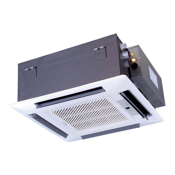
40GJ*C
Cassette Ductless Split System
Sizes 12 to 24
NOTE: Read the entire instruction manual before starting the
installation.
Please read this Owner's Information Manual carefully before installing and using this appliance
and keep this manual for future reference.
For your convenience, please record the model and serial numbers of your new equipment in the
spaces provided. This information, along with the installation data and dealer contact information,
will be helpful should your system require maintenance or service.
UNIT INFORMATION
Model #
Serial #
INSTALLATION INFORMATION
Date Installed
Owner' s Manual
the environmentally sound refrigerant
NOTE TO EQUIPMENT OWNER:
DEALERSHIP CONTACT INFORMATION
Company Name:
Address:
Phone Number:
Technician Name:
Advertisement

Subscribe to Our Youtube Channel
Related Manuals for Carrier 40GJ


Summary of Contents for Carrier 40GJ
- Page 1 40GJ*C Cassette Ductless Split System Sizes 12 to 24 Owner' s Manual the environmentally sound refrigerant NOTE: Read the entire instruction manual before starting the installation. NOTE TO EQUIPMENT OWNER: Please read this Owner’s Information Manual carefully before installing and using this appliance and keep this manual for future reference.
-
Page 3: User Notice
User Notice When operating, the entire capacity of the cooperating indoor unit should be not larger than 150% of outdoor unit. Otherwise, it will cause the shortage of cooling (heating) capacity. A Breaker(or fuse) need to be installed in every indoor unit, and the capacity should in according with indoor unit’s electrical parameter;... -
Page 4: Table Of Contents
Contents Safety Information ....................1 Install of The Compact Panel Cassette Type Indoor Unit ......... 2 Constitutes and Names of Parts of Compact Panel Cassette Type Indoor Unit ..10 Working Temperature Range .................. 11 Malfunction Debarring .................... 12 Maintenance Method ....................14... -
Page 5: Safety Information
Safety Information Safety Information Please read this manual carefully before use this unit, and operate it correctly according to the guide in this manual. Please take specially note to the meaning of these two marks: Warning!: This mark means that it may cause casualty or badly heart if the operation is incorrect. Note!: This mark means that it may cause casualty or property loss if the operation is incorrect. -
Page 6: Install Of The Compact Panel Cassette Type Indoor Unit
Install of The Compact Panel Cassette Type Indoor Unit Install of The Compact Panel Cassette Type Indoor Unit Schematic diagram of installation spaces 59 in (1500 mm) 59 in (1500 mm) 40GJQB12C--3 10 1/4 in in/mm 40GJQB18C--3 (260 mm) 40GJQB24C--3 Select install location of the indoor unit blown though all the room. - Page 7 Install of The Compact Panel Cassette Type Indoor Unit Dimension of ceiling opening and location of the hoisting screw (M10) 25 3/5 in (650 mm) 22 4/9 in (570 mm) 15 3/4 in (400 mm) 26 7/9 in (680 mm) 33 in(8 40 mm) 35 in(8 90 mm) 37 2/5 in (950 mm)
- Page 8 Install of The Compact Panel Cassette Type Indoor Unit e of the drainage pipe at the outlet vent by bolt. 4 Check if the unit is horizontal. Inner drainage pump and bobber switch are included in the indoor unit, check if 4 angle of every unit malfunction of the bobber switch and lead water drop.) 5 Backout the gasket anchor board used to prevent gasket break off and tighten the nut on it.
- Page 9 Install of The Compact Panel Cassette Type Indoor Unit Smear freeze motoroil here Median sponge (attachment) (entwine the wiring interface with seal mat) Thread fasten(x4) Torque wrench Heat preservation sheath of liquid inlet tube (attachment) (for liquid tube) Spanner Heat preservation sheath of gas collection tube (attachment)(for Gas collection tube...
- Page 10 Install of The Compact Panel Cassette Type Indoor Unit Sponge(attachment) Clamp(attachment) Clamp Sponge (gray) Drain hose Below 1/6 in (4 mm) Fig.7 Drain stepup pipe note The install height of the drain raising pipe should less than 11 in (280 mm). The drain raising pipe should form a right angle with the unit, and distance to unit should not beyond 300mm.
- Page 11 Install of The Compact Panel Cassette Type Indoor Unit 4 in (100 mm) Fig.11 Electrical wiring Note:The power of the entire indoor unit must be connected in outdoor unit. About the electrical wiring, please see the circuit diagram attached with the unit. All the installation of electrical wiring must be done by professional personnel.
- Page 12 Install of The Compact Panel Cassette Type Indoor Unit Install the panel 2. Install the panel Install the panel on the indoor unit temporarily. When install, hang the latch on the hook that is located Hang the remaining 2 latches to the hooks on the sides of the indoor unit.(Be careful not to let the swing motor lead wire get caught in the sealing material.) Screw the 4 hexagon head screws under the latches in about 3/5 in (15 mm).
- Page 13 Install of The Compact Panel Cassette Type Indoor Unit 2. If gap still exist between ceiling and decoration panel after tightening the screws, readjust the height of If the raising lever and drain hose are not affect, can adjust the height of indoor unit by the hole on the corner of panel.
-
Page 14: Constitutes And Names Of Parts Of Compact Panel Cassette Type Indoor Unit
Constitutes and Names of Parts of Compact Panel Cassette Type Indoor Unit Constitutes and Names of Parts of Compact Panel Cassette Type Indoor Unit 40GJQB12C--3 40GJQB18C--3 40GJQB24C--3... -
Page 15: Working Temperature Range
Working Temperature Range Working Temperature Range 80.6 F(27 C) 66.2 F(19 C) 95 F(35 C) 75.2 F(24 C) 89.6 F(32 C) 73.4 F(23 C) 118.4 F(48 C) 78.8 F(26 C) 69.8 F(21 C) 59 F(15 C) 64.4 F(18 C) 68 F(20 C) 44.6 F(7 C) 42.8 F(6 C) 59 F(15 C) -
Page 16: Malfunction Debarring
Malfunction Debarring Malfunction Debarring Warning! Cut down the main power switch immediately if malfunction (such as smell the burning odor etc.) happened, and then contact service center. If the abnormal state is maintained, the unit may be damaged or Check the following items before contacting maintenance center Phenomena Reason Remedial Measures... - Page 17 Malfunction Debarring Instruction If problem still cannot found out after above checking, please contact service center and instruct phenomena and model. The following circumstance are not malfunction “Malfunction” Reason Start up unit immediately after turned The overload protects switch makes it run after 3 minutes delay.
-
Page 18: Maintenance Method
Maintenance Method Maintenance Method When air conditioner won’t be used for a long time, please cut off the main power supply of air conditioner. Warning! Do turn off the unit and cut off the main power supply when cleaning the air conditioner, otherwise electric shock or harm may happen. - Page 19 Maintenance Method Fig.19 Fig.20 Clean air inlet grille 1. Open air inlet grille (the same with the 1st step of Clean Air Filter) 3. Take out air inlet grille Open air inlet grille for an angle of 45 4. Clean Clean it by pubescence brush, water and neutral cleaning, then throw water or dry it.
- Page 20 Maintenance Method Function and usage period for air purifying Could adsorb CO, CO , benzene, aldehydes and odor of gasoline etc.. Usage period is 6 months to 1 year. If it is necessary to be changed, purchase new purifier in the nearest Gree special engaged maintenance center.
- Page 24 Catalog No: 40GJC-01OM Copyright 2014 Carrier Corporation S 7310 W. Morris St. S Indianapolis, IN 46231 Edition Date: 11/14 Manufacturer reserves the right to change, at any time, specifications and designs without notice and without obligations. Replaces: New...
Need help?
Do you have a question about the 40GJ and is the answer not in the manual?
Questions and answers