Advertisement
Table of Contents
- 1 Table of Contents
- 2 Parts List
- 3 Safety Considerations
- 4 System Requirements
- 5 Dimensions
- 6 Dimensions 5
- 7 Clearances
- 8 Clearances 7
- 9 Installation Guide
- 10 Indoor Unit Installation
- 11 Outdoor Unit Installation
- 12 System Vacuum and Charge
- 13 Start- -Up
- 14 Troubleshooting
- Download this manual
See also:
Service Manual
38GVM / 40GVM
Multi---Split High---Wall Ductless Split System
38GVM --- Size 18k, 24k, 30k, 36k and 42k
40GVM --- Size 9k, 12k, and 18k
NOTE: Read the entire instruction manual before starting the installation.
38GVM
Installation Instructions
40GVM
A12567
TABLE OF CONTENTS
. . . . . . . . . . . . . . . . . . . . . . . . . . . . . . . . . . . . . . .
. . . . . . . . . . . . . . . . . . . . . . . . . . . . . . . . . . . .
. . . . . . . . . . . . . . . . . . . . . . . . . . . . . . . . . . .
. . . . . . . . . . . . . . . . . . . . . . . . . . . . .
. . . . . . . . . . . . . . . . . . . . . . . . . . . . . . . . . . . . . . . .
. . . . . . . . . . . . . . . . . . . . . . . . . . .
PAGE
. . . . . . . . . . . . . . . . . . . . . . . . .
. . . . . . . . . . . . . . . . . . . . . . . .
. . . . . . . . . . . . . . . . . . . . . . .
. . . . . . . . . . . . . . . . .
10- -11
. . . . . . . . . . . . . . . . . . .
14- -15
2
3
3- -4
5- -7
7- -8
9
9
12
13
Advertisement
Table of Contents

Subscribe to Our Youtube Channel
Related Manuals for Carrier 38GVM Series


Summary of Contents for Carrier 38GVM Series
-
Page 1: Table Of Contents
38GVM / 40GVM Multi---Split High---Wall Ductless Split System 38GVM --- Size 18k, 24k, 30k, 36k and 42k 40GVM --- Size 9k, 12k, and 18k Installation Instructions NOTE: Read the entire instruction manual before starting the installation. TABLE OF CONTENTS PAGE PARTS LIST . -
Page 2: Parts List
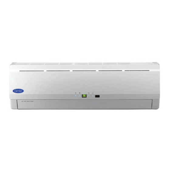
PARTS LIST Part No. Part Name Mounting Plate Mounting Screws Remote Control Remote Control Holder Conversion Joint Varies. See CJ Table A09655a A09653 Air in Front Panel Louver Air out Display Closeup Remote control holder Drain Hose Air intake Connecting Pipe and Connecting Wires Air outlet A09652... -
Page 3: Safety Considerations
SAFETY CONSIDERATIONS SYSTEM REQUIREMENTS Installing, starting up, and servicing air- -conditioning equipment Allow sufficient space for airflow and servicing unit. See Fig. 7 can be hazardous due to system pressures, electrical components, through 9 for minimum required clearances. and equipment location (roofs, elevated structures, etc.). Piping Only trained, qualified installers and service mechanics should IMPORTANT: Both refrigerant lines must be insulated... - Page 4 Refrigerant Charge Charge Additional Charge Additional Charge Unit Size Metering Device oz. (kg.) Required After ft. (m) oz./ft. (g/m) 18 K 47.6 (1.35) 20 (6.1) 0.21 (20) 24 K 77.6 (2.2) 30 (9.1) 0.21 (20) 30 K 77.6 (2.2) 40 (12.2) 0.21 (20) 36 K 102.2 (2.9)
- Page 5 DIMENSIONS - - INDOOR A08289 Net Operating Weight Unit Size In. (mm) In. (mm) In. (mm) Lbs. (Kg) 33.3 (846) 10.7 (272) 7.1 (180) 22.0 (10) 33.3 (846) 10.7 (272) 7.1 (180) 22.0 (10) 37.0 (940) 11.7 (297) 7.9 (201) 29.0 (13) Fig.
-
Page 6: Dimensions
DIMENSIONS - - OUTDOOR (CONTINUED) 35.1 (892) 13.4 (341) 15.6 (396) 37.2 (946) 22.0 (560) Unit: in. (mm) A12553 Fig. 4 --- 38GVM024/030 024 Weight, lb (kg): Gross - - 146 (66.2) / Net - - 135 (61.2) 030 Weight, lb (kg): Gross - - 148 (67.1) / Net - - 137 (62.1) 39.1 (994) 36.2 (920) 24.0 (610) -
Page 7: Clearances
DIMENSIONS - - OUTDOOR (CONTINUED) 42.8 (1087) 40.0 (1015) 24.8 (631) Unit: in. (mm) (191) A12555 Fig. 6 --- 38GVM042 Weight, lb (kg): Gross - - 247 (112.3) / Net - - 225 (102.3) CLEARANCES - - INDOOR CEILING 6" (0.15m) min. 5"... -
Page 8: Clearances 7
CLEARANCES - - OUTDOOR 20 (508) minimum space above top of unit 11.8 (300) minimum space 11.8 (300) on air inlet side minimum distance from wall 24.0 (610) minimum space on service valve side 78 (2000) minimum space in front of Unit: in. -
Page 9: Installation Guide
Fig. 12 --- Refrigerant Line Routing S Do not install the indoor or outdoor units in a location with special environmental conditions. For those applications, contact your Carrier Representative. If piping is going through the back: INDOOR UNIT INSTALLATION 1. Determine pipe hole position using the mounting plate as a template. -
Page 10: Outdoor Unit Installation
OUTDOOR UNIT INSTALLATION INSTALL ALL POWER AND INTERCONNECTING WIRING TO OUTDOOR UNIT 1. Use a rigid base to support unit in a level position. 2. Locate outdoor unit and connect piping and wiring. CAUTION Strong wind EQUIPMENT DAMAGE HAZARD Failure to follow this caution may result in equipment damage or improper operation. - Page 11 Covered conduit connection for size 18k only Outdoor unit Terminal Block Conduit panel Conduit 38GVM-40GVM 18K - 42K Connection Diagram This Series of Connections Will be Repeated for Each Indoor Unit (A to A - B to B etc.) CONNECTING CABLE OUTDOOR TO INDOOR Main Power to...
-
Page 12: System Vacuum And Charge
SYSTEM VACUUM AND CHARGE Deep Vacuum Method The deep vacuum method requires a vacuum pump capable of CAUTION pulling a vacuum of 500 microns and a vacuum gage capable of accurately measuring this vacuum depth. The deep vacuum method is the most positive way of assuring a system is free of air and UNIT DAMAGE HAZARD liquid water. -
Page 13: Start- -Up
START- - UP Test Operation Explain Following Items To Customer With The Aid Of The Owner’s Manual: Perform test operation after completing gas leak and electrical 1. How to turn air conditioner on and off; selecting safety check. COOLING, HEATING and other operating modes; setting 1. -
Page 14: Troubleshooting
TROUBLESHOOTING 38GVM Diagnostic Codes Indoor and/or Indoor Unit Wired 36 and 42K Outdoor Unit 18, 24, and 30K Display Control Error Defrost Mode 1 Outdoor Defrost Mode 2 Outdoor See Error Code Inlet tube temperature sensor malfunction Inlet tube temperature sensor malfunction Indoor Table See Error Code... - Page 15 TROUBLESHOOTING (CONTINUED) Error Code Table Error Error Error Error Description Error Description Error Description Code Code Code Unit A indoor pipe outlet temperature Unit B indoor pipe outlet temperature Unit C indoor unit pipe outlet sensor malfunction sensor malfunction temperature sensor malfunction Unit A indoor pipe inlet temperature Unit B indoor pipe inlet temperature Unit C indoor unit pipe inlet...
- Page 16 Catalog No: 38---40GVM---2SI Edition Date: 07/13 Copyright 2013 CAC / BDP S 7310 W. Morris St. S Indianapolis, IN 46231 Replaces: 38--- 40GVM--- 1SI Manufacturer reserves the right to change, at any time, specifications and designs without notice and without obligations.
Need help?
Do you have a question about the 38GVM Series and is the answer not in the manual?
Questions and answers