Table of Contents
Advertisement
Quick Links
AIR CONDITIONER
INSTALLATION MANUAL
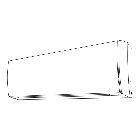
INDOOR UNIT (Wall Mounted Type)
For authorized service personnel only.
INSTALLATION MANUAL
INDENDØRSENHED (Vægmonteret type)
Kun til autoriseret servicepersonale.
ASENNUSOHJE
SISÄYKSIKKÖ (seinälle asennettava malli)
Vain valtuutetuille huoltohenkilöille.
INSTALLASJONSVEILEDNING
INNENDØRSENHET (veggmontert modell)
Kun for autorisert servicepersonell.
INSTALLATIONSHANDBOK
INOMHUSENHET (väggmonterad)
Endast för auktoriserad servicepersonal.
INSTRUKCJA MONTA U
URZ DZENIE WEWN TRZNE (do monta u ciennego)
Do u ytku wyá cznie przez autoryzowany personel obsáugi technicznej.
PART NO. 9319357034
Advertisement
Table of Contents

Related Manuals for Fujitsu ASYG14LTCB


Summary of Contents for Fujitsu ASYG14LTCB
-
Page 1: Air Conditioner
AIR CONDITIONER INSTALLATION MANUAL INDOOR UNIT (Wall Mounted Type) For authorized service personnel only. INSTALLATION MANUAL INDENDØRSENHED (Vægmonteret type) Kun til autoriseret servicepersonale. ASENNUSOHJE SISÄYKSIKKÖ (seinälle asennettava malli) Vain valtuutetuille huoltohenkilöille. INSTALLASJONSVEILEDNING INNENDØRSENHET (veggmontert modell) Kun for autorisert servicepersonell. INSTALLATIONSHANDBOK INOMHUSENHET (väggmonterad) Endast för auktoriserad servicepersonal. -
Page 2: Table Of Contents
AIR CONDITIONER INSTALLATION MANUAL CAUTION Compact Wall Mounted Type P/N 9319357034 Do not place any other electrical products or household belongings under indoor unit Contents or outdoor unit. Dripping condensation from the unit might get them wet, and may cause damage or SAFETY PRECAUTIONS …………………………………………………………………... -
Page 3: General Specification
2. 4. Accessories CAUTION Install heat insulation around both the gas and liquid pipes. Failure to do so may The following installation accessories are supplied. Use them as required. cause water leaks. Name and Shape Q’ty Name and Shape Q’ty Use heat insulation with heat resistance above 120 °C. -
Page 4: Installation Work
INSTALLATION WORK 6. 5. Cutting the knockout hole Cutting the knockout hole for piping on under cover: 6. 1. Installation dimensions The piping can be connected in the 6 directions indicated in the following. When the piping is connected in direction (2), (3), (4) or (5), use a cutting tool to cut along Wall hook the groove for the piping that will coming out of the under cover. - Page 5 [Installing the indoor unit] 6. 8. Forming the drain hose and pipe • Hang the indoor unit from the hooks at the top of the wall hook bracket. • Insert the spacer, etc. between the indoor unit and the wall hook bracket and separate [Rear piping, Right piping, Bottom piping] the bottom of the indoor unit from the wall.
-
Page 6: Electrical Wiring
6.9.2. Bending pipes 7. 2. Indoor unit wiring • If pipes are shaped by hand, be careful not to collapse them. (1) Remove the wire cover. (Remove the 1 screw.) • Do not bend the pipes in an angle more than 90°. (2) Remove the cable clamp. -
Page 7: Finishing
FINISHING FRONT PANEL REMOVAL AND INSTALLATION 9. 1. Intake grille removal (1) Insulate between pipes. • Insulate suction and discharge pipes separately. • For rear, right, and bottom piping, overlap the connection pipe heat insulation and (1) Open the intake grille. indoor unit pipe heat insulation and bind them with vinyl tape so that there is no (2) While holding the intake grille, lift up the grille stay and secure the intake grille. -
Page 8: Test Run
9. 4. Front panel installation REMOTE CONTROLLER INSTALLATION (1) First, ¿ t the lower part of the front panel, and insert top and bottom hooks. (2 top CAUTION sides, 7 bottom sides, 2 center) Check that the indoor unit correctly receives the signal from the remote controller, Indoor unit then install the remote controller holder. - Page 9 12.2.3. Installing relay control board and relay wire terminal 12. 1. Accessories (Communication kit) Control unit board The following installation accessories are supplied. Use them as required. Name and Shape Q’ty Description Connector (CN8) Relay control board For connecting the wired remote control Relay wire unit and external...
-
Page 10: Selecting The Remote Controller Signal Code
FUNCTION SETTING Installing the external connect kit terminal (sold separately) Connect the wire of external input/output to the board of external connect kit. Perform the “FUNCTION SETTING” according to the installation conditions using the EXTERNAL INPUT CONNECT TO NO. CNA01 EXTERNAL OUTPUT CONNECT TO NO. -
Page 11: Customer Guidance
Heating Room Temperature Correction CUSTOMER GUIDANCE Depending on the installed environment, the room temperature sensor may require a cor- rection. Explain the following to the customer in accordance with the operating manual: The settings may be changed as shown in the table below. (1) Starting and stopping method, operation switching, temperature adjustment, timer, air À... - Page 12 Heat sink temp. sensor error ¸ • Sub-cool Heat Ex. gas inlet temp. sensor error ¸ • Sub-cool Heat Ex. gas outlet temp. sensor error Liquid pipe temp. sensor error ¸ Current sensor error ¸ • Discharge pressure sensor error ¸...
Need help?
Do you have a question about the ASYG14LTCB and is the answer not in the manual?
Questions and answers