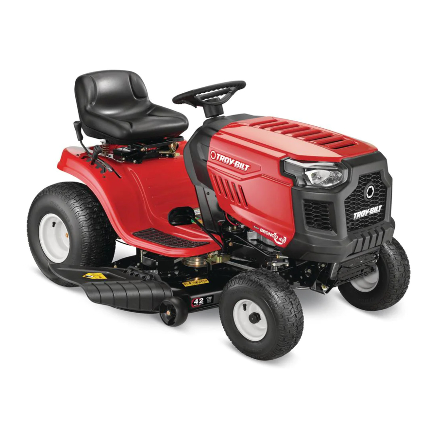
Troy-Bilt Bronco Operator's Manual
Automatic
Hide thumbs
Also See for Bronco:
- Operator's manual (88 pages) ,
- Operation manual (48 pages) ,
- Operator's manual (72 pages)
Table of Contents
Advertisement
Available languages
Available languages
Safe Operation Practices • Set-Up • Operation • Maintenance • Service • Troubleshooting • Warranty
O
'
M
peratOr
s
anual
Automatic Lawn Tractor — Bronco
WARNING
READ AND FOLLOW ALL SAFETY RULES AND INSTRUCTIONS IN THIS MANUAL
BEFORE ATTEMPTING TO OPERATE THIS MACHINE.
FAILURE TO COMPLY WITH THESE INSTRUCTIONS MAY RESULT IN PERSONAL INJURY.
TROY-BILT, P.O. BOX 361131 CLEVELAND, OHIO 44136-0019
Printed In USA
Form No. 769-08417
(November 1, 2012)
Advertisement
Chapters
Table of Contents

Related Manuals for Troy-Bilt Bronco


Summary of Contents for Troy-Bilt Bronco
- Page 1 READ AND FOLLOW ALL SAFETY RULES AND INSTRUCTIONS IN THIS MANUAL BEFORE ATTEMPTING TO OPERATE THIS MACHINE. FAILURE TO COMPLY WITH THESE INSTRUCTIONS MAY RESULT IN PERSONAL INJURY. TROY-BILT, P.O. BOX 361131 CLEVELAND, OHIO 44136-0019 Printed In USA Form No. 769-08417...
-
Page 2: Table Of Contents
Visit us on the web at www.troybilt.com See How-to Maintenance and Parts Installation Videos at www.troybilt.com/tutorials ◊ Call a Customer Support Representative at (800) 828-5500 or (330) 558-7220 ◊ Write us at Troy-Bilt • P.O. Box 361131 • Cleveland, OH • 44136-0019... -
Page 3: Safe Operation Practices
Important Safe Operation Practices WARNING! This symbol points out important safety instructions which, if not followed, could endanger the personal safety and/or property of yourself and others. Read and follow all instructions in this manual before attempting to operate this machine. Failure to comply with these instructions may result in personal injury. - Page 4 A missing or damaged discharge cover can cause blade Slope Operation contact or thrown object injuries. Slopes are a major factor related to loss of control and tip-over Stop the blade(s) when crossing gravel drives, walks, or accidents which can result in severe injury or death. All slopes roads and while not cutting grass.
- Page 5 Service Children Tragic accidents can occur if the operator is not alert to the Safe Handling of Gasoline: presence of children. Children are often attracted to the machine and the mowing activity. They do not understand To avoid personal injury or property damage use extreme the dangers.
-
Page 6: Spark Arrestor
Do not modify engine Periodically check to make sure the blades come to complete stop within approximately (5) five seconds after To avoid serious injury or death, do not modify engine in any operating the blade disengagement control. If the blades way. -
Page 7: Safety Symbols
Safety Symbols This page depicts and describes safety symbols that may appear on this product. Read, understand, and follow all instructions on the machine before attempting to assemble and operate. Symbol Description READ THE OPERATOR’S MANUAL(S) Read, understand, and follow all instructions in the manual(s) before attempting to assemble and operate DANGER—... - Page 8 2 — i ection mportant peration racticeS...
-
Page 9: Assembly & Set-Up
Assembly & Set-Up Assembly & Set-Up Tractor Set-Up Shipping Brace Removal WARNING! Connecting the Battery Cables Make sure the riding mower’s engine is off, remove the ignition key, and set the parking brake before removing the shipping brace. Refer to CALIFORNIA PROPOSITION 65 WARNING the Controls and Features section for instructions on Battery posts, terminals, and related accessories... - Page 10 Attaching The Steering Wheel If the steering wheel for your tractor did not come attached, the hardware for attaching it has been packed within the steering wheel, beneath the steering wheel cap. Carefully pry off the steering wheel cap and remove the hardware. With the wheels of the tractor pointing straight forward, place the steering wheel over the steering shaft.
- Page 11 Tire Pressure To Add Gasoline Turn the engine off and let engine cool at least 2 minutes WARNING! Maximum tire pressure under any before removing the fuel cap. The gasoline tank is located circumstances is 30 psi. Equal tire pressure should be under the hood.
- Page 12 Setting the Deck Gauge Wheels Move the tractor on a firm and level surface, preferably pavement, and proceed as follows Select the height position of the cutting deck by placing the deck lift lever in the normally desired mowing height setting (any of the six different cutting height notches on the right fender).
-
Page 13: Controls & Features
Controls & Features Ignition Switch Throttle/Choke Lever Brake Pedal Parking Brake Lever Drive Pedal Shift Lever Deck Lift Lever Cup Holder PTO (Blade Engage) Lever NOTE: Steering wheel not shown for clarity Figure 4-1 Lawn Tractor controls and features are illustrated in Figure 4-1 and described on the following pages. WARNING! Read and follow all safety rules and instructions in this manual, including the entire Operation section, before attempting to operate this machine. -
Page 14: Parking Brake
Throttle / Choke Control Shift Lever The throttle control lever is located on the left side The shift lever is located on the left side of the fender and has of the tractor’s dash panel. This lever controls the three positions, FORWARD, NEUTRAL and REVERSE. The tractor speed of the engine, as well as the choke when it must not be in motion when the moving shift lever. -
Page 15: Drive Pedal
Drive Pedal Deck Lift Lever The drive pedal is located on the right side of the Found on your tractor’s right fender, the deck lift tractor, along the running board. Depress the lever is used to change the height of the cutting drive pedal forward and the tractor will move in deck. -
Page 16: Operation
Operation Engaging the Parking Brake To engage the parking brake: Fully depress the brake pedal and hold it down with your foot. Move the parking brake lever down into the parking brake position. Release the brake pedal to allow the parking brake to engage. -
Page 17: Stopping The Engine
Stopping the Engine Driving On Slopes Refer to the SLOPE GAUGE in the Important Safe Operation WARNING! If you strike a foreign object, stop the Practices section in the front of this manual to help determine engine, disconnect the spark plug wire(s) and slopes where you may operate the tractor safely. - Page 18 Using the Deck Lift Lever Headlights To raise the cutting deck, move the deck lift lever to the left, then • The Headlights are ON whenever the tractor’s engine is place it in the notch best suited for your application. Refer to running.
-
Page 19: Maintenance & Adjustment
Maintenance & Adjustments Maintenance WARNING: Before performing any maintenance or repairs, disengage PTO, move shift lever into neutral position, set parking brake, stop engine and remove key to prevent unintended starting. Engine Refer to the Engine Operator/Owner Manual for engine maintenance instructions. - Page 20 Cleaning the Engine And Deck Charging IMPORTANT: When charging your tractor’s battery, use only a Any fuel or oil spilled on the machine should be wiped off charger designed for 12V lead-acid batteries. Read your battery promptly. Do NOT allow debris to accumulate around the cooling charger’s Owner’s Manual prior to charging your tractor’s battery.
-
Page 21: Seat Adjustment
Adjustments Side to Side If the cutting deck appears to be mowing unevenly, a side to side WARNING: Never attempt to make any adjustment can be performed. Adjust if necessary as follows: adjustments while the engine is running, except With the tractor parked on a firm, level surface, place the where specified in the operator’s manual. -
Page 22: Maintenance Schedule
Maintenance Schedule Before Every Every Every Every Prior Each use 10 Hours 25 Hours 50 Hours 100 Hours to Storing Clean Hood/Dash Louvers Check Engine Oil Level Check Air Filter for Dirty, Loose or Damaged Parts Clean and Re-oil Air Filter’s Foam Precleaner Replace Air Filter Element Change Engine Oil and Replace Oil Filter Clean Battery Terminals... -
Page 23: Service
Service Cutting Deck Removal To remove the cutting deck, proceed as follows: Place the PTO (Blade Engage) lever in the disengaged (OFF) position and engage the parking brake. Lower the deck by moving the deck lift lever into the bottom notch on the right fender. Remove the belt-keeper rod, from around the tractor’s engine pulley, by removing the self-tapping screw (A) that secures it. -
Page 24: Cutting Blades
Connect the second cable (negative –) to the other post of the jumper battery. Make the final connection on the engine block of the tractor, away from the battery. Attach to a unpainted part to assure a good connection. CAUTION: If the jumper battery is installed on a vehicle (i.e. -
Page 25: Changing The Deck Belt
Place a block of wood between the center deck housing WARNING! A poorly balanced blade will cause baffle and the cutting blade to act as a stabilizer. See Figure excessive vibration, may cause damage to the 7-5. tractor and/or result in personal injury. Test the blade’s balance using a blade balancer. -
Page 26: Dealer
Carefully remove the deck belt from around the two While holding the belt and pulley together, rotate the spindle pulleys and the two deck idler pulleys. See Figure pulley to the left. Continue holding and rotating the pulley 7-7. and belt until the belt is fully rolled into the PTO pulley. To place the new belt, begin by routing the belt around the Changing the Transmission Drive Belt two outer spindle pulleys as shown in Figure 7-7. -
Page 27: Troubleshooting
Troubleshooting Problem Cause Remedy Engine fails to start 1. PTO/Blade engaged. 1. Place PTO lever the in disengaged (OFF) position. 2. Spark plug wire disconnected. 2. Connect wire to spark plug. 3. Fuel tank empty, or stale fuel. 3. Fill tank with clean, (less than 30 days old) gas. 4. -
Page 28: Replacement Parts
Replacement Parts Component Part Number and Description 954-04060B Deck Belt (42” Mowing Deck) 918-04822A Deck Spindle Blade (42” Deck) 942-04308 942-04308-X Extreme Blade (42” Deck) 925-1707D Battery 951-12179A Fuel Tank Cap Fuel Tank Cap (CA Models Only) 951-12426 625-05002 Key Asm-Black Key W/Keychain 734-1731 Tire (Front) 15 x 6 x 6 Square Shoulder 734-1730... -
Page 29: Attachments & Accessories
Attachments & Accessories The following attachments and accessories are compatible for the Troy-bilt Lawn Tractor. See the retailer from which you purchased your tractor, an authorized Troy-bilt Service Dealer or phone (800) 828-5500 for information regarding price and availability. CAUTION: This Troy-Bilt Lawn Tractor is NOT designed for use with any type of ground-engaging attachments (e.g. - Page 30 FEDERAL and/or CALIFORNIA EMISSION CONTROL WARRANTY STATEMENT YOUR WARRANTY RIGHTS AND OBLIGATIONS MTD Consumer Group Inc, the United States Environmental Protection Agency (EPA), and, for those products certified for sale in the state of California, the California Air Resources Board (CARB) are pleased to explain the emission (evaporative and/or exhaust) control system (ECS) warranty on your outdoor 2006 and later small off-road spark-ignited engine and equipment (outdoor equipment engine) In California, new outdoor equipment engines must be designed, built and equipped to meet the State’s stringent anti-smog standards (in other states, 1997 and later model year equipment must be designed, built, and equipped to meet the U.S.
- Page 31 Add-on or modified parts that are not exempted by the Air Resources Board may not be used. The use of any non-exempted add-on or modified parts by the ultimate purchaser will be grounds for disallowing a warranty claims. MTD Consumer Group Inc will not be liable to warrant failures of warranted parts caused by the use of a non-exempted add-on or modified part.
-
Page 32: Warranty
MANUFACTURER’S LIMITED WARRANTY FOR The limited warranty set forth below is given by Troy-Bilt LLC with Routine maintenance items such as lubricants, filters, blade respect to new merchandise purchased and used in the United States sharpening, tune-ups, brake adjustments, clutch adjustments,... -
Page 33: Español
Visite nuestro sitio web en www.troybilt.com. Ver Vídeos demostrativos de instalación de mantenimiento y piezas en www.troybilt.com/Tutorials ◊ Llame al representante de Atención al Cliente al (800) 828-5500 o (330) 558-7220 ◊ Escríbanos a Troy-Bilt • P.O. Box 361131 • Cleveland, OH • 44136-0019... -
Page 34: Medidas Importantes De Seguridad
Medidas importantes de seguridad ADVERTENCIA: La presencia de este símbolo indica que se trata de instrucciones importantes de seguridad que se deben respetar para evitar poner en peligro su seguridad personal y/o material y la de otras personas. Lea y siga todas las instrucciones de este manual antes de poner en funcionamiento esta máquina. - Page 35 Esté atento a la cortadora y a la dirección de la descarga Los datos estadísticos muestran que los operadores de 60 de los aditamentos y no apunte a nadie. Nunca opere la años y mayores se ven involucrados en un alto porcentaje cortadora de césped sin que estén en su lugar apropiado la de lesiones relacionadas con tractores corta césped.
- Page 36 Servicio No cambie a transmisión neutral para descender. El exceso de velocidad puede hacer que el operador pierda el control de la máquina, ocasionando lesiones graves e incluso la muerte. Manejo seguro de la gasolina: No remolque cargas pesadas detrás de los aditamentos Para evitar lesiones personales o daños materiales sea (carrito de basura cargado, podadora de rodillos, etc) en sumamente cuidadoso al manipular la gasolina.
- Page 37 Antes de limpiar, reparar o inspeccionar la máquina, Según la Comisión de Seguridad de Productos para el compruebe que la(s) cuchilla(s) y todas las partes en Consumidor de los Estados Unidos (CPSC) y la Agencia movimiento se hayan detenido. Desconecte el cable de la de Protección Ambiental de los Estados Unidos (EPA), bujía y póngalo haciendo masa contra el motor para evitar este producto tiene una vida útil media de siete (7) años,...
- Page 38 Símbolos De Seguridad Esta página representa y describe la seguridad los símbolos que pueden parecer en este producto. Lea, comprenda, y siga todas instrucciones de la máquina antes de intentar ensamblar y operar. Symbol Description LEA EL MANUAL(S) DEL OPERADOR leído, entienda, y siga todas las instrucciones en el manual(s) antes de procurar montar y funcionar PELIGRO—...
- Page 39 2 — M ection edidaS iMportanteS de Seguridad...
-
Page 40: Montaje Y Configuración
Montaje y Configuración Configuración Posición de la zona roja de caucho sobre el terminal de la batería DEL TRACTOR positivo para ayudar a proteger de la corrosión. NOTA: Este Manual del operador cubre una gama de NOTA: Si la batería se pone en servicio después de especificaciones de productos de varios modelos. - Page 41 ¡ADVERTENCIA! Deslice el asiento hacia atrás en el soporte de pivote del La plataforma de la cortadora de asiento, alineando la ranura central trasera en el soporte de césped puede arrojar objetos. En caso de operar la pivote con el agujero que queda en la base del asiento. cortadora de césped sin colocar la cubierta de descarga en la posición adecuada para el Seleccione la posición deseada para el asiento y fíjelo con el...
- Page 42 Presión de los neumáticos Llenado de gasolina y aceite El tanque de gasolina está ubicado debajo del capó y posee una ¡ADVERTENCIA! La presión máxima de los capacidad de 1-1/2 galones. No lo llene en exceso. neumáticos en cualquier circunstancia es de 30 psi. Se debe mantener una presión uniforme para todos ¡ADVERTENCIA! Tenga mucho cuidado al trabajar...
- Page 43 Ajuste de las ruedas de calibración de la plataforma Mueva el tractor a una superficie firme y nivelada, preferentemente sobre el pavimento, y realice lo siguiente. Seleccione la posición de altura de la plataforma de corte colocando la palanca de elevación de la plataforma en el ajuste de altura de corte deseado en situación normal (cualquiera de las seis muescas de altura de corte del lado derecho del guardabarros).
-
Page 44: Controles Y Características
Controles y Características Palanca de estrangulador/ interruptor de encendido obturador Pedal de freno Alquiler de palanca Conducir Pedal de freno Palanca de cambios Titular de la Palanca de potencia de arranque Copa (PTO) (enganche de cuchilla) Palanca de elevación de la plataforma Figura 4-1 Los controles y características del tractor corta césped se ilustran en la y se describen en las páginas siguientes. -
Page 45: Freno De Estacionamiento
Palanca de cambios PALANCA DE CONTROL DEL REGULADOR La palanca de control del estrangulador está ubicada La palanca de cambios está ubicada del lado izquierdo del del lado derecho del tablero de instrumentos del guardabarros y tiene tres posiciones, MARCHA DIRECTA, tractor. - Page 46 Conducir Pedal Palanca de elevación de la plataforma Ubicada en el guardabarros derecho del tractor, la La unidad de pedal se encuentra en el lado palanca de elevación de la plataforma se utiliza para derecho del tractor, a lo largo del estribo. Presione cambiar la altura de la plataforma de corte.
-
Page 47: Funcionamiento
Funcionamiento Colocación del freno de mano ADVERTENCIA Para colocar el freno de mano: Presione totalmente el pedal del embrague-freno y PARA EVITAR LESIONES manténgalo hacia abajo con el pie. PERSONALES GRAVES O LA MUERTE Mueva la palanca de control de velocidad totalmente hacia abajo en la posición de freno de mano. - Page 48 Detención del motor Operación en pendientes Consulte el INDICADOR DE PENDIENTES en la sección Medidas ¡ADVERTENCIA! Si golpea contra algún objeto importantes de seguridad del manual para contribuir a extraño, detenga el motor, desconecte el(los) determinar en qué pendientes puede operar el tractor con cable(s) de la bujía y conecte el motor a masa.
- Page 49 Utilización de la palanca de elevación de la plataforma Faros delanteros Para elevar la plataforma de corte, mueva la palanca de elevación • Los faros están encendidos cuando el motor del tractor se de la plataforma hacia la izquierda y colóquela en la muesca que está...
-
Page 50: Mantenimiento Y Ajustes
Mantenimiento y Ajustes Retire la tapa de llenado de aceite / varilla medidora del MANTENIMIENTO tubo de llenado de aceite.embalado con su máquina. ¡ADVERTENCIA! Antes de realizar tareas de Empuje la manguera de drenaje de aceite (llena de mantenimiento o reparaciones, desconecte la este manual) en el puerto de drenaje de aceite. - Page 51 Limpieza del motor y de la plataforma Carga IMPORTANTE: Cuando cargue la batería de su tractor, utilice Si se derrama combustible o aceite sobre la máquina, debe únicamente un cargador diseñado para 12V de plomo-ácido. limpiarse de inmediato. NO permita que se acumulen desechos alrededor de las aletas de refrigeración del motor ni en ninguna Lea el Manual del Operador del cargador de la batería antes de otra parte de la máquina.
- Page 52 Ajustes Nivelación lado a lado Si la plataforma de corte estuviera realizando el corte de césped ADVERTENCIA: Nunca la tentativa de hacer de forma despareja, puede realizarse un ajuste lado a lado. De ser cualquier ajuste mientras el motor corre, excepto necesario, realice un ajuste de la siguiente manera: donde especificado en el manual del operador.
- Page 53 Ajuste del freno de mano Si el tractor no se detiene por completo cuando se presiona totalmente el pedal de freno, o si las ruedas traseras del tractor ¡ADVERTENCIA! Nunca intente ajustar los frenos siguen rodando con el freno de mano colocado, el freno necesita con el motor en marcha.
-
Page 54: Servicio
Servicio Extracción de la plataforma de corte Para extraer la plataforma de corte, proceda de la siguiente manera: Coloque la toma de fuerza (PTO) (enganche de cuchilla) en la posición OFF (desconectada) y coloque el freno de mano. Baje la plataforma colocando la palanca de elevación de la plataforma dentro de la muesca inferior en el guardabarros derecho. - Page 55 Arranque por medio de conexión en puente ¡ADVERTENCIA! Nunca arranque una batería dañada o congelada con conexiones en puente. Asegúrese de que los vehículos no se toquen y los encendidos están apagados. No permite que las abrazaderas de los cables se toquen. Conecte el cable positivo (+) al borne positivo (+) de la batería descargada de su tractor.
- Page 56 Cuchillas de corte ¡ADVERTENCIA! Antes de extraer la(s) cuchilla(s) para afilarla(s) o reemplazarla(s), asegúrese de apagar el motor, retirar la llave de encendido, desconectar el(los) cable(s) de la bujía y hacer masa contra el motor para impedir el encendido accidental del motor. Proteja sus manos utilizando guantes pesados o un paño para asir la cuchilla de corte.
- Page 57 Para colocar la correa nueva, empieza haciendo que el cinturón alrededor de las dos poleas exterior del huso, como se muestra en la Figura 7-7. Luego, la cinta de ruta alrededor de las dos polines poleas de la cubierta como se muestra en la Figura 7-7. Hex Washer Screws Volver a apretar la barra poseedor del cinturón aflojado antes.
-
Page 58: Solución De Problemas
Solución de Problemas Problema Causa Solución El motor no arranca 1. La potencia de arranque (PTO)/cuchilla está 1. Coloque la perilla (o palanca) en posición OFF conectada. (desenganchada). 2. Se ha desconectado el cable de la bujía. 2. Conecte el cable a la bujía. 3. -
Page 59: Piezas De Reemplazo
Piezas de reemplazo Componente Número de Parte y Descripción 954-04060B Cinturón de Paseo 918-04822A Huso de Cubierta Lámina 942-04308 (42“ plataforma de corte) 942-04308-X Extremo Lámina (42“ plataforma de corte) 925-1707D Batería 951-12179A Gorra de Depósito de combustible 951-12426 Gorra de Depósito de combustible (CA) 625-05002 Llave de montaje-Key Negro con llavero 734-1731... -
Page 60: Aditamentos Y Accesorios
Aditamentos y accesorios Los siguientes documentos y los accesorios son compatibles para el tractor del césped Troy-bilt. Consulte al minorista a quien (800) 828-5500 le adquirió su tractor, a un distribuidor autorizado Troy-bilt de mantenimiento o llame al teléfono para obtener información sobre precios y disponibilidad. - Page 61 Notas...
- Page 62 DECLARACIÓN FEDERAL y/o DE CALIFORNIA SOBRE GARANTÍAS EN EL CONTROL DE EMISIONES SUS DERECHOS Y OBLIGACIONES EN CUANTO A LA GARANTÍA MTD Consumer Group Inc, la Agencia de Protección Medioambiental de los Estados Unidos (EPA), y para aquellos productos certificados para su venta en el es- tado de California, el Departamento de los Recursos del Aire de California (CARB) se complacen en explicar la garantía que cubre al sistema de control (ECS) de emisiones (evaporativas y/o de escape) de su equipo y motor (motor de equipos de exteriores) de encendido por chispa para todo terreno, pequeño, de exteriores del año 2006 y años posteriores En California, los nuevos motores de equipos de exteriores deben estar diseñados, construidos y equipados para cumplir con las...
- Page 63 8. Durante la totalidad del período de garantía del motor y equipo para todo terreno arriba mencionado, MTD Consumer Group Inc mantendrá un suministro de piezas bajo garantía suficiente para satisfacer la demanda esperada de tales piezas. 9. Cualquier pieza de reemplazo se podrá usar para el cumplimiento del mantenimiento o las reparaciones bajo garantía y se suministrarán sin cargo para el propietario.
-
Page 64: Garantía
Las disposiciones de esta garantía cubren el recurso de reparación para cuchillas, dientes, bolsas para pasto, ruedas, ruedas para la única y exclusiva que surge de la venta. Troy-Bilt no se hará plataforma de la podadora tractor, asientos, zapatas antideslizantes, responsable de ninguna pérdida o daño incidental o resultante,...
Need help?
Do you have a question about the Bronco and is the answer not in the manual?
Questions and answers
How to shift gears properly on Bronco Auto
To shift gears properly on a Troy-Bilt Bronco Auto, follow these steps:
1. Ensure the Mower is Stopped – Always come to a complete stop before shifting gears.
2. Press the Brake Pedal – Fully depress the brake/clutch pedal to disengage the drive system.
3. Move the Shift Lever – Gently shift the gear selector into the desired position (Forward, Reverse, or Neutral).
4. Release the Brake Slowly – Gradually release the brake/clutch pedal to engage the gear smoothly.
5. Check for Proper Operation – If shifting feels difficult or the mower moves unexpectedly, inspect the drive belt and linkage for proper adjustment and wear.
If shifting remains hard or the mower continues moving when the brake is applied, check the drive belt installation, pulley movement, and ensure the belt disengages properly.
This answer is automatically generated
how to lower the grass chute on a 2025 bronco