
Related Manuals for Heatrae Sadia Megaflo Eco SystemFit 145sf


Summary of Contents for Heatrae Sadia Megaflo Eco SystemFit 145sf
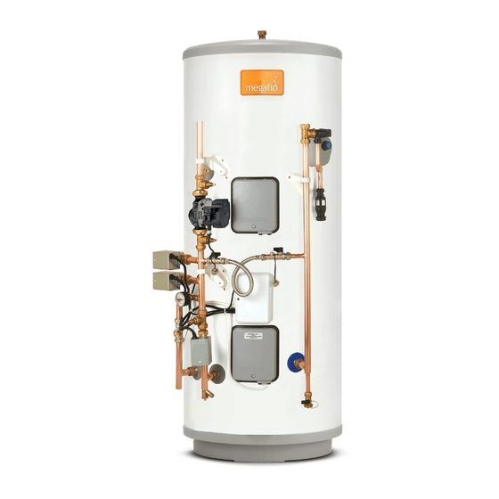
- Page 1 Megaflo Eco SystemFit Unvented Indirect Hot Water Cylinders Important Please read & understand all these instructions before commencing installation. Please leave this manual with the customer for future reference...
-
Page 2: Table Of Contents
Contents 1. Introduction....................3 1.1 General ....................3 1.2 Symbols used .................... 3 1.3 Abbreviations ................... 3 1.4 Liabilities ....................3 2. Safety ......................4 2.1 General safety warnings ................4 2.2 Recommendations ..................4 2.3 Specific safety instructions ................ 4 3. -
Page 3: Introduction
In the interest of UK customers, we are continuously 1. Introduction endeavouring to make improvements in product quality. All the specifications stated in this document are therefore 1.1 General subject to change without notice. The following instructions are offered as a guide to the Our liability as the manufacturer may not be invoked in user and installer. -
Page 4: Safety
2.3 Specific safety instructions 2. Safety WARNING TO USER 2.1 General safety warnings If water discharges from the temperature/ DANGER pressure relief valve on the cylinder shut down the boiler/immersion heaters. Do This cylinder is unvented and as such becomes not turn off any water supply. -
Page 5: Technical Specifications
3. Technical specifications 3.1 Technical data: Max direct kW rating Immersion heat up times (Btm immersion, 3kW) Coil surface area (m²) 0.58 0.72 0.79 0.79 0.79 0.79 15l/min 21.9 23.2 31.5 32.0 40.1 42.3 Primary Coil heat up 30l/min 17.4 20.0 25.1 25.3... -
Page 6: Dimensions
3.2 Dimensions and connections Table 3: General dimensions table - Indirect Item 125I 145l 170I 210I 250I 300I 895 1020 1095 1323 1574 1102 1229 1384 1486 1738 2053 934 1011 1238 1526 Figure 1: General dimensions - Indirect Honeywell 2 Port Motorised Valves: Danfoss TP9000 Programmable Thermostat Model No.: V4043H with timed Domestic... -
Page 7: Circulating Pump Set-Up
3.3 Circulating pump set-up In this case, unlock the key lock by pressing the button for 10 seconds. Primary Circulating Pump: (d) During a period of 10 seconds, press shortly Model No.: Grundfos UPM3 Auto L 25-70 130 on the ‘ ’ and the pump switches to the next Working pressure: 1 MPa (10 bar) max. - Page 8 Control Mode explanation • PP1: lowest proportional pressure curve Proportion pressure • PP2: Intermediate The head pressure is reduced at falling heat proportional pressure demand and increased at rising heat demand. curve The duty point of the circulator will move up or down on the selected proportional pressure •...
-
Page 9: Electrical Diagram(S)
3.4 Electrical diagram(s) PROGRAMMER - HEATING ZONE 1 PROGRAMMABLE INDIRECT (DHW) & DOMESTIC HOT WATER ROOM THERMOSTAT THERMAL CONTROLS ZONE VALVE (SUPPLIED) FOR ZONE 2 (SUPPLIED) (SUPPLIED FITTED) (SUPPLIED FITTED) ROOM SENSOR (SUPPLIED) N.B. A DOUBLE POLE ISOLATING SWITCH MUST BE INSTALLED IN THE MAINS SUPPLY 1 2 3 14 15 16... - Page 10 Access to Control Unit: Control Housing Details Disconnect from mains supply before removing any covers. Removing the Control Cover. Unscrew the large screw using a flat ended screw driver. Lift from bottom of cover at point indicated until cover comes away freely. Replacing the Control Cover: Tilt and align the top 2 lugs in the holes indicated.
-
Page 11: Description Of The Product
4.5 Storage and Handling 4. Description of the product If the unit is to be stored before installation it must be 4.1 General description placed upright on a secure, level surface and be in a dry, frost free environment. The support surface must be This product is a purpose designed unvented water capable of supporting the packaged weight of the unit, heater. -
Page 12: Choice Of Location
Ensure that the floor area for the cylinder is level and Outlet/terminal fittings (taps, etc.) capable of permanently supporting the weight when The cylinder can be used with most types of terminal full of water (see table 1, page 5 for weights). fittings. -
Page 13: Installation
with unvented storage water heaters. 6. Installation Can be a sealed system or open vented type - maximum primary pressure 3 bar. 6.1 General The primary flow from the boiler must be pumped. Gravity circulation will not work due to the After reading the previous sections in this booklet and special design of the primary heat exchanger. -
Page 14: Water Connections
6.2 Water connections T&P Relief Valve Insulation A set of insulating components is supplied with the water heater and should be installed to gain maximum WARNING heat and energy saving benefits. See Figure 7 below, for installation instructions. Under no circumstances should the factory fitted temperature/pressure... - Page 15 Cold water control pack The expansion relief valve should be installed with the discharge pipework in either the horizontal CAUTION position or facing downwards. No other valves should be placed between the cold Flush supply pipework before water combination valve and the cylinder. connection to remove all flux and debris Where discharge pipework is difficult to attain, the prior to fitting the inlet controls.
- Page 16 Stopcock is grouped with the 3 Bar pressure Reducing valve. Make sure the flow is correct to the markings on the valve. 3 Bar Pressure Reducing Valve Stopcock Figure 9: Stopcock and an 8 bar pressure relief valve From 3 Bar Pressure Reducing Valve 8 Bar Expansion Relief Cartridge 22mm Compression...
- Page 17 Figure 11: Schematic installation diagram using 3bar pressure reducing valve in conjunction with 8bar pressue relief valve.
- Page 18 Secondary circulation If secondary circulation is required it is recommended In direct electric installations where a secondary that it be connected to the cylinder as shown (see fig. circulation is required particular attention should be paid by the installer to maintain the returning water 12, below).
- Page 19 Discharge Note: To comply with the Water Supply (Water Fittings) It is a requirement of Building Regulation G3 that any Regulations, the tundish should incorporate a suitable air discharge from an unvented system is conveyed to where gap. it is visible, but will not cause danger to persons in or about the building.
- Page 20 if plastic pipes are used as branch pipes carrying Worked example of discharge pipe sizing discharge from a safety device they should be either polybutylene (PB) to Class S of BS 7291-2:2006 or cross Fig. 13: shows a G1/2 temperature relief valve with a linked polyethylene (PE-X) to Class S of BS 7291-3:2006;...
- Page 21 Maximum Resistance Minimum Size Of Resistance Created Valve Outlet Minimum Size Of Allowed, Expressed As A Discharge Pipe D2 From By Each Elbow Or Size Discharge Pipe D1 Length Of Straight Pipe (I.E. Tundish Bend No Elbows Or Bends) 22mm up to 9m 0.8m G1/2...
-
Page 22: Electrical Connections
6.3 Electrical connections CAUTION In case of difficulty contact service support; contact details are available on page 36 of this booklet. The room sensor is wired directly to the programmer, not to the wiring centre. WARNING Basic programmer features:- 24 hour or 5/2 day operation. Disconnect from the mains electrical Room temperature setting at programmer. -
Page 23: Commissioning
Indirect units 7. Commissioning Fill the indirect (primary) circuit following the boiler manufacturer’s commissioning instructions. 7.1 General Ensure the filling loop hose is connected at both ends and is tight. After filling the installation with water in the previous Open the isolating valves at either end of the filling section please follow the following steps to complete the loop and allow to fill from the mains inlet supply. -
Page 24: Operation
Temperature controls – direct units immersion heater(s) 8. Operation All immersion heaters are fitted with a thermostat 8.1 General which is fitted in the centre of the heater plate and a cut-out which is fitted to the side of the thermostat. Access to the thermostat can be made by opening WARNING the immersion heater cover - DISCONNECT THE... -
Page 25: Maintenance
9. Maintenance Close hot tap, turn on isolating valve or main stop cock to the system. Check for leaks. 9.1 General Maintenance requirements Unvented hot water systems have a continuing Descaling immersion heater(s) maintenance requirement in order to ensure safe Turn off the mains water supply, isolate the electrical working and optimum performance. -
Page 26: Troubleshooting
10. Troubleshooting Water contained in the cylinder may be very hot, especially following a thermal control failure. Caution must be taken when drawing water from the unit. WARNING The fault finding chart (table 5, below) will enable Do not tamper with any of the safety valves operational faults to be identified and their possible or controls supplied with the cylinder as this causes rectified. -
Page 27: Decommissioning
Environmental information 11. Decommissioning Products are manufactured from many recyclable 11.1 Decommissioning procedure materials. At the end of their useful life they should be Isolate electrical supplies and make safe disposed of at a Local Authority Recycling Centre in order Isolate the water supply to realize the full environmental benefits. - Page 28 Pressure Reducing Valve Cartridge (3 Bar) Strainer Mesh 3 Bar Pressure Reducing Valve - Complete 95:605:886 Figure 15: Exploded view of 3bar pressure reducing valve Expansion Relief Cartridge 8 Bar Pressure Relief Valve, Complete 95:605:893 Figure 16: Exploded view of 8bar pressure relief valve Stopcock, Can Be Used Either with 3 Bar Inlet Control Valve or 8 Bar Pressure Relief Valve...
- Page 29 Indirect Control Assembly For 210 litre and above a further indirect control assembly accessory is available 95:970:554 Direct combined Mounting plate (indirect) thermostat and 95:607:931 thermal cut-out Indirect combined 95:612:717 thermostat and thermal cut-out Terminal cover (indirect) 95:612:716 95:614:118 Backnut 95:607:940 Gasket 70 351 65...
- Page 30 T&P valve 95:605:810 8 bar pressure relief valve 95:605:893 Circulating pump 70:328:42 2 port motorised valve (22mm connections) 96:605:819 Filling loop and connections 95:607:096 Pressure gauge 95:607:065 Manifold 22mm & 28mm 7034121 & 7034122 Automatic differential bypass valve 95:607:692 Drain valve (1/4 turn) 95:605:051 Wiring centre Tundish...
- Page 31 NOTES.
-
Page 32: Benchmark Checklist
Benchmark checklist... -
Page 33: Commissioning & Service Records
Commissioning & service records... - Page 34 • The Megaflo product has not been modified or tampered with in any way, other than by a Heatrae Sadia or Baxi Customer Support approved engineer.
-
Page 35: The Benchmark Scheme Guarantee
• Regular maintenance has been carried out by a competent person/, an approved engineer from Heatrae Sadia or any other part of the Baxi Group Baxi Customer Support approved engineer in accordance with the requirements set out in the maintenance section of the installation instructions. - Page 36 Megaflo may introduce modifications to their products from time to time. Consequentially the details given in this brochure are subject to alteration without notice. Contacts Specification Advice Hotline T: 01603 420220 F: 01603 420229 E: specifier@heatraesadia.com www.heatraesadia.com * Heatrae Sadia is a trading name of Baxi Heating UK Limited, Brooks House, Coventry Road, Warwick, CV34 4LL July 2015...
- Page 37 Spares Stockists Electric Water Heating Co. 2 Horsecroft Place Pinnacles Harlow Essex CM19 5BT Tel: 0845 0553811 E-Mail: sales@ewh.co.uk Special Product Division Units 9 & 10 Hexagon Business Centre Springfield Road Hayes Middlesex UB4 0TY Tel: 020 8606 3567 Parts Center Tel: 0344 292 7057 www.partscenter.co.uk Newey &...
- Page 38 NOTES.
- Page 39 NOTES.
-
Page 40: Customer Service
Customer service Telephone: 0344 8711535 Hurricane Way Norwich E-mail:mega oservice@baxi.co.uk Norfolk NR6 6EA Important notice to installations outside of the UK: References to legislation, legal requirements, regulations, building regulations benchmark, spares stockists, guarantees and warranty are ONLY APPLICABLE WITHIN THE UK. For local legislation, legal requirements, regulations, building regulations outside of the UK, contact your local Authority.
Need help?
Do you have a question about the Megaflo Eco SystemFit 145sf and is the answer not in the manual?
Questions and answers
How do I pipe two 300 litre mega flow cylinders together heated by a gas boiler
To pipe two Heatrae Sadia Megaflo Eco SystemFit 145sf cylinders together heated by a gas boiler, follow these key steps:
1. Ensure Compatibility: Do not use with solid fuel boilers or uncontrolled energy sources unless proper safety measures are added.
2. Water Supply:
- Ensure both cylinders are connected to a mains water supply with adequate pressure.
- Use the supplied cold water inlet control kits, each with a full flow isolating valve.
3. Piping Connections:
- Use 22mm compression fittings to connect pipework to the units.
- Solder fittings can be used carefully without damaging the plastic casing. Push-fit fittings are also acceptable.
- Install a suitable draining tap in the cold water supply line between the expansion valve and the heater.
4. Hot Water Outlet:
- Connect the hot water outlets of both cylinders to a common manifold if combined output is desired.
- Open hot taps furthest from the cylinders to flush and purge air during filling.
5. Heating System:
- Connect the primary heating circuit from the gas boiler to the heating coil connections on both cylinders.
- Use appropriate 28mm O/D copper pipes for 250 and 300 litre units; for 145sf, verify sizing.
- Ensure the system controls and wiring centre are connected as per the manual.
6. Safety and Location:
- Install tundishes away from electrical components.
- Ensure discharge pipes are safely routed and the environment is frost-free.
7. Filling and Commissioning:
- Close the drain cock.
- Open the isolating valve and mains stopcock to fill the cylinders.
- Do not operate immersion heaters during filling.
- Purge air by opening hot taps.
- Ensure immersion heaters are wired correctly.
This setup ensures safe and efficient operation of two Megaflo Eco SystemFit cylinders with a gas boiler.
This answer is automatically generated