Jet JMS-10X Operating Instructions And Parts Manual

Jet JMS-10X Operating Instructions And Parts Manual

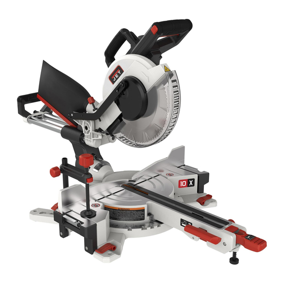
Sliding dual-bevel compound miter saw

Advertisement

This .pdf document is bookmarked
Operating Instructions and Parts Manual
Sliding Dual-Bevel Compound Miter Saw
Model JMS-10X and JMS-12X
JET
427 New Sanford Road
LaVergne, Tennessee 37086
Part No. M-707210
Ph.: 800-274-6848
Edition 1 06/2019
www.jettools.com
Copyright © 2019 JET
1

Advertisement

Table of Contents
loading
Need help?

Need help?

Do you have a question about the JMS-10X and is the answer not in the manual?

Questions and answers

Subscribe to Our Youtube Channel

Summary of Contents for Jet JMS-10X

  • Page 1 This .pdf document is bookmarked Operating Instructions and Parts Manual Sliding Dual-Bevel Compound Miter Saw Model JMS-10X and JMS-12X 427 New Sanford Road LaVergne, Tennessee 37086 Part No. M-707210 Ph.: 800-274-6848 Edition 1 06/2019 www.jettools.com Copyright © 2019 JET...
  • Page 2: Important Safety Instructions

    Do not use this saw for other than its intended 20. Maintain a balanced stance at all times so that use. If used for other purposes, JET disclaims you do not fall into the blade or other moving any real or implied warranty and holds itself parts.
  • Page 3: Miter Saw Safety Warnings

    29. Keep hands out of the line of saw blade. 49. After completing the cut, release the trigger and wait for the blade to stop before returning the 30. Don’t use in dangerous environment. Don’t use saw to raised position. power tools in damp or wet location, or expose them to rain.
  • Page 4: Table Of Contents

    Familiarize yourself with the following safety notices used in this manual: This means that if precautions are not heeded, it may result in minor injury and/or possible machine damage. This means that if precautions are not heeded, it may result in serious, or possibly even fatal, injury.
  • Page 5 12.0 Troubleshooting JMS-10X,12X Miter Saws ....................21   13.0 Replacement Parts ............................. 22   13.1.1 JMS-10X (#707210) – Miter Saw Assembly – Exploded View I ............23   13.1.2 JMS-10X (#707210) – Miter Saw Assembly – Exploded View II ............24  ...
  • Page 6: About This Manual

    If there are questions or comments, please contact your local supplier or JET. JET can also be reached at our web site: www.jettools.com.
  • Page 7: Features And Terminology

    4.0 Features and terminology Figure 4-1: Features and Terminology...
  • Page 8: Specifications

    5.0 Specifications Table 1 Model number JMS-10X JMS-12X Stock number 707210 707212 Motor and Electricals Motor type Series-wound, double insulated Input power 1.7 kW Phase single Voltage 115 V Cycle 60 Hz Listed FLA (full load amps) 15 A Motor speed 4000±10% RPM...
  • Page 9: Cutting Capacities

    = not applicable The specifications in this manual were current at time of publication, but because of our policy of continuous improvement, JET reserves the right to change specifications at any time and without prior notice, without incurring obligations.
  • Page 10: Setup And Assembly

    Use C-clamps to clamp this mounting board to a Read and understand the entire stable work surface at the worksite. contents of this manual before attempting assembly or operation. Failure to comply may 6.6 Releasing slide carriage cause serious injury. Loosen slide locking knob (A, Figure 8-1).
  • Page 11: Power Cord Storage Clips

    6.8.2 Adaptor The adaptor can be used to convert the 1-5/8 in. diameter port to 2-1/2 in. diameter, for connection to a hose used with a shop vacuum or other dust collection system. Use a hose clamp to secure the dust hose (not provided) to the saw port.
  • Page 12: Electrical Connections

    7.0 Electrical connections To avoid electrical hazards, fire hazards, or damage to the machine, use proper circuit protection. Your saw is wired at the factory for 115V operation. Connect to a 120V, 15 Amp circuit and use a 15 amp time delay fuse or circuit breaker.
  • Page 13: Adjustments

    Cord length Wire gauge (AWG) 0 – 25 ft. 25- 50 ft. Table 3 Important: Make certain the receptacle in question is properly grounded. If you are not sure, have a registered electrician check the receptacle. 8.0 Adjustments Note: Your miter saw was adjusted by the Figure 8-1: selecting miter angles manufacturer.
  • Page 14: Fence Adjustment

    8.4 Fence adjustment 8.5 Bevel adjustments 8.5.1 90° (zero) bevel stop adjustment The fence extensions must be Unplug saw from electrical outlet. extended to left or right, or removed entirely, when making bevel cuts, to prevent blade or guard Pull up bevel lock handle (A, Figure 8-4) to obstruction.
  • Page 15: Depth Adjustment

    8.6 Depth adjustment Cutting depth can be pre-set for even and repetitive shallow cuts, such as slots or dadoes. Raise cutting head. Loosen screw (F, Figure 8-8) and slide plate (G) outward. Retighten screw. Pull cutting head down until blade teeth are at desired depth of cut.
  • Page 16: General Saw Operation

    9.4 Jammed material If a jam occurs, release trigger and wait for all moving parts to stop. Unplug saw and remove jammed items. 9.5 Cutting options 9.5.1 Chop cuts For chop cutting operations on small workpieces, Figure 9-1 slide cutting head completely toward rear of unit and tighten slide lock knob (A, Figure 8-1).
  • Page 17: Cutting Bowed Material

    9.9 Crown molding Miter stops are provided at common angles of 0°, 15°, 22.5°, 31.6°, 45° left and right, and 60° right. Your compound miter saw is suited for the difficult Always push down miter lock handle (B, Figure 8-1) task of cutting crown molding.
  • Page 18: Lower Blade Guard

    10.2 Lower Blade Guard Pull out brush assembly. Notice orientation of brush as you remove it; it should be inserted in Do not use saw without lower blade guard. The the same manner; curvature of brush will match lower blade guard is attached to the saw for your curvature of motor.
  • Page 19: Crown Molding Charts

    11.0 Crown molding charts 11.1 Crown molding: 90° wall angles Crown molding compound cut with 90° walls. Bevel Miter Type of Cut Setting Setting Procedure Inside corner – Left 33.9° 31.6° 1. Position top of molding against fence. Side Right 2.
  • Page 20: Crown Molding: Various Wall Angles

    11.2 Crown molding: various wall angles Compound miter and bevel angle settings for wall-to-crown molding angles. 52/38º Crown Molding 45/45º Crown Molding 52/38º Crown Molding 45/45º Crown Molding Angle Angle 0Miter 0Bevel 0Miter 0Bevel 0Miter 0Bevel 0Miter 0Bevel Between Between 0Setting 0Setting 0Setting...
  • Page 21: Troubleshooting Jms-10X,12X Miter Saws

    12.0 Troubleshooting JMS-10X,12X Miter Saws Symptom Possible Cause Correction * Motor will not start No incoming power. Check plug connection to receptacle. If satisfactory, check electrical panel for blown fuse or tripped breaker – replace fuse or reset breaker. Low voltage.
  • Page 22: Replacement Parts

    Non-proprietary parts, such as fasteners, can be found at local hardware stores, or may be ordered from JET. Some parts are shown for reference only, and may not be available individually.
  • Page 23: Jms-10X (#707210) - Miter Saw Assembly - Exploded View I

    13.1.1 JMS-10X (#707210) – Miter Saw Assembly – Exploded View I...
  • Page 24: Jms-10X (#707210) - Miter Saw Assembly - Exploded View Ii

    13.1.2 JMS-10X (#707210) – Miter Saw Assembly – Exploded View II...
  • Page 25: Jms-10X (#707210) - Miter Saw Assembly - Parts List

    13.1.3 JMS-10X (#707210) – Miter Saw Assembly – Parts List Index No Part No Description Size 001 .... JMS10X-001 ..... Miter Angle Scale................... 1 002 .... TS-2245122 ....Socket Head Button Screw ........M5x12 ......3 003 .... TS-2284082 ....Pan Head Machine Screw ........M4x8 ......4 004 ....
  • Page 26 Index No Part No Description Size 061 .... JMS10X-061 ..... Stop Plate ...................... 1 062 .... F011908 ....Wave Washer ............8 mm ......1 063 .... JMS10X-063 ..... Flat Washer ....................1 064 .... JMS10X-064 ..... Screw ..............M6 ......... 3 065 ....
  • Page 27 Index No Part No Description Size 122 .... TS-1514021 ....Socket Head Flat Screw .......... M6x16 ....……2 123 .... JMS10X-123 ..... Dust Exhaust ....................1 124 .... JMS10X-124 ..... Linkage Bar ....................1 125 .... JMS10X-125 ..... Washer ..............6 mm ......1 126 ....
  • Page 28 219 .... JMS10X-219 ..... Washer ......................2 220 .... JMS10X-220 ..... Sleeve ......................3 221 .... JET-92 ....... JET Logo ..............92x38 mm ..... 1 222 .... JMS10X-222 ..... Rear Cover ....................1 223 .... LM000393 ....Warning Label, Laser ..................1 224 ....
  • Page 29: Jms-12X (#707212) - Miter Saw Assembly - Exploded View I

    13.2.1 JMS-12X (#707212) – Miter Saw Assembly – Exploded View I...
  • Page 30: Jms-12X (#707212) - Miter Saw Assembly - Exploded View Ii

    13.2.2 JMS-12X (#707212) – Miter Saw Assembly – Exploded View II...
  • Page 31: Jms-12X (#707212) - Miter Saw Assembly - Parts List

    13.2.3 JMS-12X (#707212) – Miter Saw Assembly – Parts List Index No Part No Description Size 001 .... JMS12X-001 ..... Miter Angle Scale................... 1 002 .... TS-2246122 ....Socket Head Button Screw ........M6x12 ......3 003 .... TS-2284082 ....Pan Head Machine Screw ........M4x8 ......4 004 ....
  • Page 32 Index No Part No Description Size 060 .... JMS10X-206 ..... Washer ......................6 061 .... JMS10X-059 ..... Locking Ring ....................5 062 .... TS-1523061 ....Socket Set Screw ............ M6x20 ......3 063 .... TS-1503051 ....Socket Head Cap Screw ......... M6x20 ......1 064 ....
  • Page 33 166 .... F001232 ....Pan Head Machine Screw ........M5-0.8x45 ..... 2 167 .... JMS10X-161 ..... Motor Housing ....................1 168 .... JET-92 ...... JET Logo ..............92x38mm ...... 1 169 .... JMS12X-169 ..... Upper Handle ....................1 170 ....
  • Page 34 Index No Part No Description Size 184 .... JMS10X-179 ..... Spring ......................2 185 .... JMS12X-185 ..... Self-Tapping Screw ..........ST2.9x9.5 mm ....2 186 .... JMS10X-177 ..... Button ......................2 187 .... JMS10X-176 ..... Button ......................2 188 ....
  • Page 35: Electrical Connections - Jms-10X,12X

    14.0 Electrical Connections – JMS-10X,12X...
  • Page 36: Warranty And Service

    JET sells through distributors only. The specifications listed in JET printed materials and on official JET website are given as general information and are not binding. JET reserves the right to effect at any time, without prior notice, those alterations to parts, fittings, and accessory equipment which they may deem necessary for any reason ®...

This manual is also suitable for:

Jms-12x

Table of Contents