Cognex DataMan 8000 Series Quick Reference Manual
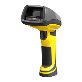
Cognex dataman 8000 series barcode reader
Hide thumbs
Also See for DataMan 8000 Series:
- Quick reference manual (32 pages) ,
- Reference manual (33 pages)
Advertisement
Table of Contents
- 1 Connection Options
- 2 Getting Started
- 3 Physical Layout
- 4 Connecting Cables
- 5 Serial Connection
- 6 Field of View and Reading Distances
- 7 Reading Codes
- 8 Map of Field of View and Reading Distances
- 9 Trigger Types
- 10 Ethernet Connection
- 11 Troubleshooting an Ethernet Connection
- 12 Laser Information
- 13 Agency Compliance Statements
- 14 Reader Control Codes
- 15 Keyboard Language
- Download this manual
Advertisement
Table of Contents

Related Manuals for Cognex DataMan 8000 Series


Summary of Contents for Cognex DataMan 8000 Series
- Page 1 ® COGNEX DataMan 8000 Series ® Quick Reference Guide...
-
Page 2: Connection Options
Page 4 Page 2 Getting Started Section Title xxxx • xxxxx • xxxxx • xxxxx • xxxxx DataMan 8000 Accessories • Physical Layout Connection Options Page 6 Connecting Cables • USB and Ethernet Connections • Serial Connection • Keyboard Emulation Field of View and Reading Distances • Reading Codes • Page 14 Reading Codes with the Trigger Types DataMan 8000 Install DataMan 8000 Software • Start the Setup Tool DataMan Software Page 19 • Use the Setup Tool Menu Bar • Troubleshooting an Ethernet Connection Compliance Information, Warnings Page 25 DataMan 8000 Speciications • Laser Information • Agency Compliance Statements and Notices ii ... -
Page 3: Physical Layout
Physical Layout DataMan 8000 Accessories LASER LIGHT, DO NOT STARE INTO BEAM Serial/USB slide-in Ethernet slide-in Laser aimer DMCM-SERIALM-00 DMCM-ENETM-00 UltraLight (DataMan 8500 only) RS-232 cable, 2.5 m RS-232 cable, 5 m Lanyard hook DM8000-RS232-02 DM8000-RS232-05 USB cable (requires PS/2 adapter cable Trigger additional power DM700-PS2-00 (press and supply), 2.75 m hold to read) DM8500-USB-00 Indicator Light Ethernet cable, 5 m Ethernet cable, 2.5 m RED: No read GREEN: Read DM8000-ECABLE-02 DM8000-ECABLE-05 Power Supply POE adapter Cable lock... -
Page 4: Connecting Cables
Connecting Cables WARNING Disconnect DataMan from power before inserting/removing communication modules. 2. With a 2 mm Allen Wrench, tighten the screws so that the slide-in is irmly locked. 1. C onnect either the Serial/USB slide-in (DMCM-SERIALM-00) or the Ethernet slide-in (DMCM-ENETM-00) depending on your desired connection type. 6 DataMan 8000 Quick Reference Guide DataMan 8000 Quick Reference Guide 7... - Page 5 3. Insert the plug and slide the cable lock up 4. Twist the cable lock in place. to the reader. Connect the cables depending on your desired connection type. Choose one of the following: For an Ethernet connection, you also need a Power Over Ethernet • For DataMan 8100 and 8500, use the DM8000-RS232-02 cable (2.5 meters) Adapter (CPS-AC-POE1A-xx). or the DM8000-RS232-05 cable (5 meters) For a PS/2 connection, you also need a PS2 Adapter Cable (DM700- • For DataMan 8100 and 8500 with USB, use the DM8500-USB-00 cable (with PS2-00). external power supply) • For DataMan 8100 and 8500 with Ethernet, use the DM8000-ECABLE-02 For extra power supply, use the DataMan 8000 Power Supply (DM100- (2.5 meters) or the DM8000-ECABLE-05 (5 meters) PWR-000). See pages 10-13 for the different connection options. 8 DataMan 8000 Quick Reference Guide DataMan 8000 Quick Reference Guide 9...
-
Page 6: Serial Connection
USB and Ethernet Connections Serial Connection 1. Connect the USB cable to the Reserved USB port. 2. (For DataMan 8500 only:) Connect an external power +6 VDC supply. +6 VDC PWR 1. Connect the Ethernet cable to the POE adapter. 2. Plug in the POE adapter (CPS- AC-POE1A-xx) and connect the Ethernet cable to the network or to your PC. 1. 6VDC power supply (DM100-PWR-000), a 5.5mm x 2.1mm DC Power Plug 2. S erial cable. Provide +5 to +6 VDC to connector on pin 1. 10 DataMan 8000 Quick Reference Guide DataMan 8000 Quick Reference Guide 11... - Page 7 Keyboard Emulation with Keyboard Keyboard Emulation without Keyboard 1. Scan the PS/2 Keyboard Emulation Enable Coniguration Code (from 1. Connect the PS/2 keyboard adapter to your unpowered PC. the Reader Coniguration Codes document, available though the 2. Start up your PC. Windows Start menu.) 3. Power up your reader. 2. Disconnect your reader’s serial cable from your PC. 4. Scan the PS/2 Keyboard Emulation Disable Coniguration Code (from 3. Power down your PC and unplug your reader from power. the Reader Coniguration Codes document, available through the 4. Connect the PS/2 keyboard adapter to your PC. Windows Start menu). 5. Connect your reader’s serial cable to the PS/2 keyboard adapter and 5. Connect your reader to an RS-232 cable and then to the PS/2 plug in your reader to power. keyboard adapter. 6. Power up your PC and start reading codes. 6. Start reading codes. You can change your reader’s coniguration by scanning the appropriate You can change your reader’s coniguration by switching back to the Coniguration Codes. serial interface and connecting to the Setup Tool. 12 DataMan 8000 Quick Reference Guide DataMan 8000 Quick Reference Guide 13...
-
Page 8: Field Of View And Reading Distances
Field of View and Reading Distances Reading Codes There is a range of reading distances available for different code sizes • Hold the reader approximately perpendicular to the code being read. and focus positions. Select a focus position that allows you to read the • Use the laser aimer to locate the code. desired code sizes at the desired working distance. • Refer to the permitted working distances. • Press and hold the trigger to read the code. • If your application has a consistent reading range, set the focus range to a limited depth of ield with no steps (for example, set it to 20) or with limited steps (for example, set it to 2 steps between 0 and 30). This way, you can achieve fast performance. • If your application has a variety of code types and sizes, set the focus range to a wider depth of ield with increased number of steps (for example, set it to 6 steps between 0 and 200). This way, you can make sure your code is in focus. For a map of the ield of view and reading distances, see pages 16-17. 14 DataMan 8000 Quick Reference Guide DataMan 8000 Quick Reference Guide 15... -
Page 9: Map Of Field Of View And Reading Distances
Map of Field of View and Reading Distances NOTE: Beyond 300 mm external illumination may be required. 396 mm (15.5 in) 312 mm (12.2 in) 154 mm (6.06 in) 33 mm (1.29 in) 5 mil 75 mm (2.9 in) 10 mil 210 mm (8.2 in) 20 mil 374 mm (14.7 in) 7 mil 215 mm (8.4 in) 13 mil 409 mm (16.1 in) -
Page 10: Trigger Types
Trigger Types Install DataMan 8000 Software 1. Check the DataMan Release Notes for a full list of The DataMan 8000 trigger mode determines when the reader attempts to read a code. Use the Setup Tool to change trigger types. system requirements. 2. Insert CD-ROM and follow the on-screen prompts. The following trigger types are supported: 3. Connect the DataMan 8000 to your PC. 4. Launch the Setup Tool and click Refresh. • Presentation: Repeatedly scans for a symbol and decodes it The reader appears under COM ports or Network devices. whenever one is detected. The reader relies on an internal timing 5. Select a COM port or a Network devices listing mechanism to acquire images. • Manual (default): Begins acquiring images when you press the and click Connect. trigger button on the reader, and continues acquiring images until a symbol is found and decoded or you release the button. RS-232/USB connection Ethernet connection “DM8_00” with last 6 characters of ... - Page 11 Start the Setup Tool Trigger button Latest image Context based help Connect the reader to the Setup Tool to conigure it with the type of symbologies it will decode as well as other parameters, such as the type of trigger it will use and the format of the results it will generate. Connect to Reader Establish a connection to the reader Results Display View results Light and Imager Settings/ UltraLight Settings Choose a trigger type and other acquisition parameters System Settings Conigure visual and audio feedback, trigger and output actions Read history Connection status 20 DataMan 8000 Quick Reference Guide DataMan 8000 Quick Reference Guide 21...
- Page 12 Use the Setup Tool Menu Bar Each reader can store its current set of run-time parameters to a coniguration Use the Edit menu for standard Cut, Copy and Paste operations. (.cfg) ile, which contains information such as the enabled symbologies and Use the View menu to view reader information (serial number, irmware how any output data should be formatted. version, and so on) and to enable and disable various elements of the The same coniguration ile can be loaded onto multiple readers, as the ile Setup Tool, and the Tasks menu to switch between various Setup Tool does not contain identiication information such as the IP address or device options. name of the reader used to create it. Use the System menu to manage the current settings on the reader A reader can also generate a Cognex device coniguration (.cdc) ile, which and to upgrade the features it currently supports: stores the set of run-time parameters plus any identiication data, such as the name of the device, its IP address, subnet mask, and so on. Cognex System Menu recommends generating a device coniguration ile for each reader to allow you to restore a reader to its operating state with minimal effort. Save Settings Save the current parameters to non-volatile memory, which allows the reader to restore Use the File menu of the Setup Tool to manage .cfg and .cdc iles: these settings each time you reboot it. Reset Coniguration Reset all coniguration parameters in RAM File Menu (volatile memory) to the default settings Open Coniguration Open a saved .cfg coniguration ile. except for communication settings. Save Coniguration Create a .cfg coniguration ile of current run-...
-
Page 13: Troubleshooting An Ethernet Connection
Troubleshooting an Ethernet Connection Speciications and Precautions Based on your network coniguration, the Setup Tool may not be Weight 326 g able to communicate with the reader and it will not appear in the list of Network devices. Operating Temperature 0ºC — 40ºC (32ºF — 104ºF) First check your Ethernet connection with the reader and click Storage Temperature -40ºC — 60ºC (-40ºF — 140ºF) Refresh in the Setup Tool. Next, scan the Enable DHCP code in Maximum Humidity 95% (non-condensing) the DM8000 Coniguration Codes document available from the Start menu. This might allow the reader to acquire a suitable IP address Codes Data Matrix ;... -
Page 14: Laser Information
Laser Information Agency Compliance Statements The DataMan 8000 series meets or exceeds the requirements of all applicable standards organiza- tions for safe operation. However, as with any electrical equipment, the best way to ensure safe LASER LIGHT, DO NOT STARE INTO BEAM: CLASS 2 LASER PRODUCT operation is to operate them according to the agency guidelines that follow. - Page 15 Cognex Corporation shall not be liable for use of our product with equipment (i.e., power supplies, In order to avoid the dissemination of those substances in our environment and to diminish the personal computers, etc.) that is not CE marked and does not comply with the Low Voltage Directive.
-
Page 16: Reader Control Codes
Spanish Japanese Copyright © 2010 Cognex Corporation All Rights Reserved. This document may not be copied in whole or in part, nor transferred to any other media or language, without the written permission of Cognex Corporation. The hardware and portions of the software described in this document may be covered by one or more of the U.S.
Need help?
Do you have a question about the DataMan 8000 Series and is the answer not in the manual?
Questions and answers