Table of Contents
Advertisement
Advertisement
Table of Contents

Related Manuals for Prexiso G5


Summary of Contents for Prexiso G5
- Page 1 Prexiso G4/G5 User Manual Version 1.0...
- Page 2 The type and serial number of your product are indicated on the type plate. tion Enter the type and serial number in your manual and always refer to this information when you need to contact your agency or Prexiso authorised service workshop. Type: _____________________________________ Serial No.:...
- Page 3 SD Card Association All other trademarks are the property of their respective owners. Validity of this This manual applies to the G4/G5 instruments. Differences between the models are manual marked and described. G4/G5 | 3...
- Page 4 Manual to a basic level are contained in the User Manual. Provides an overview of the product together with technical data and safety directions. Refer to the following resources for all G4/G5 documentation/software: • the Prexiso G4/G5 CD • www.prexiso.com...
-
Page 5: Table Of Contents
Operating Principles Operation Equipment Setup 3.1.1 Setting up as a Real-Time Base 3.1.2 Setting up as a Post-Processing Base 3.1.3 Setting Up as a Real-Time Rover 3.1.4 Fixing the handheld to a holder and pole G4/G5 | 5 Table of Contents... -
Page 6: Table Of Contents G4/G5
G4/G5 | 6 Table of Contents 3.1.5 Connecting to a Personal Computer 3.1.6 Configuring the Instrument 3.1.7 The Mechanical Reference Plane, MRP Batteries 3.2.1 Operating Principles 3.2.2 Battery for instrument Working with the Data Storage Device Working with the RTK Device... -
Page 7: G4/G5
Electromagnetic Compatibility EMC FCC Statement, Applicable in U.S. Technical Data G4/G5 Technical Data 6.1.1 Tracking Characteristics 6.1.2 Accuracy 6.1.3 Technical Data Conformity to National Regulations 6.2.1 G4/G5 International Limited Warranty, Software Licence Agreement Appendix A Pin Assignments and Sockets Instrument... -
Page 8: Description Of The System
Survey field software The software used on the handheld for performing various surveying applications. Instruments Depending on the satellite systems and signals configured, a maximum number of 72 channels (G4) or 120 channels (G5) is allocated. Instrument Description Up to 14 L1, 14 L2 channels (GPS), 12 L1, 12 L2 channels... - Page 9 (GLONASS), Galileo, code and phase, real-time capable For GLONASS tracking a licence key has to be uploaded to the instrument with Prexiso Assistant. Available models G4 GSM-UHF G4 GSM G5 GSM-UHF G5 GSM *1 removable G4/G5 | 9 Description of the System...
-
Page 10: Container Contents
G4/G5 | 10 Description of the System 1.2 Container Contents Container for instru- ment and accesso- ries a) PBA202 batteries b) G4/G5 instrument Antennas of device d) PPC210 base pole e) Connection screw Carrier g) Tribrach h) Measuring tape USB cable... -
Page 11: Instrument Components
LEDs, ON/OFF button and Function button e) LEMO port 2 TNC connector for UHF antenna A Bluetooth port is included inside the instrument to enable connectivity to a controller. G4/G5 | 11 Description of the System... -
Page 12: System Concept
(xx.bin) ment. Software upload The firmware can be uploaded using Prexiso Assistant. Uploading instrument firmware can take some time. Ensure that the battery is at least 75% full before beginning the upload, and do not remove the battery during the upload process. -
Page 13: Power Concept
1.4.2 Power Concept General Use the Prexiso batteries, chargers and accessories or accessories recommended by Prexiso to ensure the correct functionality of the instrument. Power options Power for the instrument can be supplied either internally or externally. Internal power supply: One PBA202 battery fitting into the instrument. -
Page 14: Data Storage Concept
G4/G5 | 14 Description of the System 1.4.3 Data Storage Concept Description Data (GNSS raw data and RINEX data) can be recorded on a microSD card or internal memory. microSD card: The instrument has a microSD card holder fitted as Data storage device standard. -
Page 15: User Interface
2 User Interface 2.1 Keyboard Keyboard a) ON/OFF button b) Function button G4/G5 | 15 User Interface... - Page 16 G4/G5 | 16 User Interface ON/OFF button Button Function ON/OFF • Turn on instrument: Hold button for 1 s. While the instrument is booting all LEDs are lighted (except the blue Bluetooth LED and the red Power LED). Once the instrument has started, the normal LED behaviour starts.
- Page 17 If the red Satellite, UHF or GPRS LED is on, the communication of the internal GNSS board, radio module or GSM module might not work correctly. The instrument starts beeping. Press any key to reboot the instrument and contact your local Prexiso dealer. G4/G5 | 17 User Interface...
- Page 18 G4/G5 | 18 User Interface Function button The function described assumes that the instrument is turned on. Button Function Function • Switch datalink Press and hold button for 1 s to switch between the data- link options UHF, GPRS and Bluetooth. The corresponding green LED flashes.
-
Page 19: Operating Principles
To turn on the instrument press and hold the ON/OFF button for 1 s. Turn off instrument To turn off the instrument press and hold the ON/OFF button for 3 s until the instru- ment beeps 3 times and only the red power LED is lighted. G4/G5 | 19 User Interface... -
Page 20: Operation
G4/G5 | 20 Operation 3 Operation 3.1 Equipment Setup 3.1.1 Setting up as a Real-Time Base The following equipment setup is used for real-time base stations with the need of optimal radio coverage. Raw observation data can also be collected for post-... - Page 21 Equipment setup - G4/G5 a) G4/G5 instrument b) PBA202 battery RTK antenna d) PPC210 base pole e) Connection screw Carrier g) Tribrach h) Tripod Getac PPS236 handheld G4/G5 | 21 Operation...
- Page 22 G4/G5 | 22 Operation Equipment setup Step Description step-by-step Set up the tripod. Mount the tribrach on the tripod. Ensure that the tribrach is over the marker. Mount and level the carrier on the tribrach. Mount the connection screw on the carrier.
-
Page 23: Setting Up As A Post-Processing Base
3.1.2 Setting up as a Post-Processing Base The following equipment setup is used for static operations over markers. Equipment setup - G4/G5 a) G4/G5 instrument b) PBA202 battery Connection screw d) Carrier e) Tribrach Tripod g) Getac PPS236 handheld G4/G5 | 23... - Page 24 G4/G5 | 24 Operation Equipment setup Step Description step-by-step Set up the tripod. Mount the tribrach on the tripod. Ensure that the tribrach is over the marker. Mount and level the carrier on the tribrach. Mount the connection screw on the carrier.
-
Page 25: Setting Up As A Real-Time Rover
3.1.3 Setting Up as a Real-Time Rover The following equipment setup is used for real-time rover. Equipment setup - G4/G5 a) G4/G5 instrument b) PBA202 battery RTK antenna d) PPC200 pole e) Pole holder Getac PPS236 handheld G4/G5 | 25... - Page 26 G4/G5 | 26 Operation Equipment setup Step Description step-by-step Attach the pole holder to the ZPC200 pole. Refer to "3.1.4 Fixing the hand- held to a holder and pole". Clip the handheld into the holder and lock it by tighten the screw on the holder.
-
Page 27: Fixing The Handheld To A Holder And Pole
3.1.4 Fixing the handheld to a holder and pole Components of the Clamp a) Locking pin pole holder b) Tightening screw Pole clamp Holder d) Tightening screw e) Pin Zenith20_017 G4/G5 | 27 Operation... - Page 28 G4/G5 | 28 Operation Fixing the handheld Step Description to the holder step- Insert the pole into the clamp hole. by-step Tighten the clamp with the tightening screw. To attach the holder to the clamp insert the pin into the catch of the clamp while pushing down the locking pin.
-
Page 29: Connecting To A Personal Computer
Description The instrument is connected to a Personal Computer via USB cable. After estab- lishing a connection, the Prexiso Assistant software can be used to set up and configure the instrument, export data from the internal memory or microSD card, enter licence keys and upload firmware. - Page 30 PC Step Description Start the PC. Start Prexiso Assistant by double-clicking the shortcut from the desktop of your PC. Plug the USB cable into Port 1 of the instrument. Turn on the instrument. Plug the USB cable into the USB port of the PC.
-
Page 31: Configuring The Instrument
3.1.6 Configuring the Instrument Description The instrument can be set up as real-time rover or as real-time base by configuring the instrument with the handheld, using Prexiso Assistant or pressing a button combination. Refer to "Button combination". G4/G5 | 31... -
Page 32: The Mechanical Reference Plane, Mrp
G4/G5 | 32 Operation 3.1.7 The Mechanical Reference Plane, MRP Description The Mechanical Reference Plane: • is where the antenna heights are measured to. • is where the phase centre variations refer to. • varies for different antennas. MRP for instrument The MRP for the instrument is shown in the diagram. -
Page 33: Batteries
+10°C to +20°C/+50°F to +68°F if possible. • It is normal for the battery to become warm during charging. Using the chargers recommended by Prexiso, it is not possible to charge the battery if the temper- ature is too high. •... - Page 34 G4/G5 | 34 Operation For power adapter and charger: CAUTION The product is not designed for use under wet and severe conditions. If unit becomes wet it may cause you to receive an electric shock. Precautions: Use the product only in dry environments, for example in buildings or vehicles.
-
Page 35: Battery For Instrument
Turn the instrument over to gain access to the battery compartment. Press in the two push buttons located on both sides of the battery housing and pull the housing from the battery compartment. The battery is attached to the housing. G4/G5 | 35 Operation... - Page 36 Place the battery housing on top of the battery compartment and press the housing down until it locks into position. WARNING If charged or discharged, batteries not recommended by Prexiso may be damaged. They may burn and explode. Precautions: Only charge and discharge batteries recommended by Prexiso.
-
Page 37: Working With The Data Storage Device
Do not bend the card. • Protect the card from direct impacts. Failure to follow these instructions could result in data loss and/or permanent damage to the card. Insert and remove a microSD card step- by-step G4/G5 | 37 Operation... - Page 38 G4/G5 | 38 Operation Step Description The microSD card is inserted into a holder inside the battery compartment of the instrument. Remove the battery housing from the battery compartment. Refer to "Insert and remove battery step-by-step" for further information. Loosen the screws of the metal plate and remove the plate to gain access to the microSD card holder.
-
Page 39: Working With The Rtk Device
Devices fitted into the instrument GSM: Telit GC864-QUAD Radio: SATEL SATELLINE M3-TR1, transceive Insert and remove a SIM card step-by- step Step Description The SIM card is inserted into a holder inside the battery compartment of the instrument. G4/G5 | 39 Operation... - Page 40 G4/G5 | 40 Operation Step Description Only use SIM cards without PIN protection. Remove the battery housing from the battery compartment. Refer to "Insert and remove battery step-by-step" for further information. Loosen the screws of the metal plate and remove the plate to gain access to the SIM card holder.
-
Page 41: Led Indicators
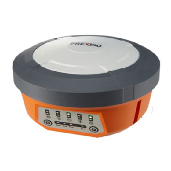
The instrument has Light Emitting Diode indicators. They indicate the basic instru- ment status. Diagram a) Satellite LEDs b) UHF LEDs GPRS LEDs d) Bluetooth LEDs e) Power LEDs Static LED g) RTK Base LED h) RTK Rover LED Record LED G4/G5 | 41 Operation... - Page 42 G4/G5 | 42 Operation Description of the IF the THEN LEDs Record LED flashing red data is recorded. Static LED the instrument is in static mode. Base LED the instrument is in base mode. Rover LED the instrument is in rover mode.
- Page 43 IF the THEN Bluetooth green a datalink via Bluetooth is available. blue a Bluetooth connection has established. Power LED green power is on. power is low (< 20%). G4/G5 | 43 Operation...
-
Page 44: Guidelines For Correct Results With Gnss Surveys
G4/G5 | 44 Operation 3.6 Guidelines for Correct Results with GNSS Surveys Undisturbed satel- Successful GNSS surveys require undisturbed satellite signal reception, especially lite signal reception at the instrument which serves as a base. Set up the instrument in locations which are free of obstructions such as trees, buildings or mountains. -
Page 45: Care And Transport
Shipping When transporting the product by rail, air or sea, always use the complete original Prexiso packaging, transport container and cardboard box, or its equivalent, to protect against shock and vibration. When transporting or shipping batteries, the person in charge of the product must... -
Page 46: Storage
G4/G5 | 46 Care and Transport 4.2 Storage Product Respect the temperature limits when storing the equipment, particularly in summer if the equipment is inside a vehicle. Refer to "6 Technical Data" for information about temperature limits. Li-Ion batteries •... -
Page 47: Cleaning And Drying
Cables and plugs Keep plugs clean and dry. Blow away any dirt lodged in the plugs of the connecting cables. Connectors with Wet connectors must be dry before attaching the dust cap. dust caps G4/G5 | 47 Care and Transport... -
Page 48: Safety Directions
G4/G5 | 48 Safety Directions 5 Safety Directions 5.1 General Introduction Description The following directions enable the person responsible for the product, and the person who actually uses the equipment, to anticipate and avoid operational hazards. The person responsible for the product must ensure that all users understand these... -
Page 49: Intended Use
Carrying out measurement tasks using various GNSS measuring techniques. • Recording GNSS and point related data. • Data communication with external appliances. • Measuring raw data and computing coordinates using carrier phase and code signal from GNSS satellites. G4/G5 | 49 Safety Directions... - Page 50 G4/G5 | 50 Safety Directions Adverse use • Use of the product without instruction. • Use outside of the intended limits. • Disabling safety systems. • Removal of hazard notices. • Opening the product using tools, for example screwdriver, unless this is permitted for certain functions.
-
Page 51: Limits Of Use
For power adapter and charger: Environment Suitable for use in dry environments only and not under adverse conditions. G4/G5 | 51 Safety Directions... -
Page 52: Responsibilities
Manufacturers of The manufacturers of non Prexiso accessories for the product are responsible for non Prexiso accesso- developing, implementing and communicating safety concepts for their products,... - Page 53 The person responsible for the product must ensure that it is used in accordance with the instructions. This person is also accountable for the training and the deploy- ment of personnel who use the product and for the safety of the equipment in use. G4/G5 | 53 Safety Directions...
-
Page 54: Hazards Of Use
G4/G5 | 54 Safety Directions 5.5 Hazards of Use WARNING The absence of instruction, or the inadequate imparting of instruction, can lead to incorrect or adverse use, and can cause accidents with far-reaching human, mate- rial, financial and environmental consequences. - Page 55 Inadequate securing of the working site can lead to dangerous situations, for example in traffic, on building sites, and at industrial installations. Precautions: Always ensure that the working site is adequately secured. Adhere to the regula- tions governing safety and accident prevention and road traffic. G4/G5 | 55 Safety Directions...
- Page 56 G4/G5 | 56 Safety Directions WARNING If computers intended for use indoors are used in the field there is a danger of elec- tric shock. Precautions: Adhere to the instructions given by the computer manufacturer regarding field use with Prexiso products.
- Page 57 If there is a risk of a thunderstorm, or if the equipment is to remain unused and unattended for a long period, protect your product additionally by unplugging all systems components and disconnecting all connecting cables and supply cables, for example, instrument - antenna. G4/G5 | 57 Safety Directions...
- Page 58 G4/G5 | 58 Safety Directions Lightning conduc- Suggestion for design of a lightning conductor for a GNSS system: tors 1) On non-metallic structures Protection by air terminals is recommended. An air terminal is a pointed solid or tubular rod of conducting material with proper mounting and connection to a conductor.
- Page 59 Antenna/instrument connection d) Metallic mast e) Connection to earth GS_040 WARNING Using a battery charger not recommended by Prexiso can destroy the batteries. This can cause fire or explosions. Precautions: Only use chargers recommended by Prexiso to charge the batteries. WARNING If charged or discharged, batteries not recommended by Prexiso may be damaged.
- Page 60 G4/G5 | 60 Safety Directions CAUTION During the transport, shipping or disposal of batteries it is possible for inappropriate mechanical influences to constitute a fire hazard. Precautions: Before shipping the product or disposing of it, discharge the batteries by running the product until they are flat.
- Page 61 Touching live components • Using the product after incorrect attempts were made to carry out repairs Precautions: Do not open the product. Only Prexiso authorised service workshops are entitled to repair these products. For power adapter and charger: CAUTION The product is not designed for use under wet and severe conditions. If unit becomes wet it may cause you to receive an electric shock.
- Page 62 G4/G5 | 62 Safety Directions Precautions: Attach the external antenna professionally. The external antenna must be secured additionally, for example by use of a safety cord. Ensure that the mounting device is correctly mounted and able to carry the weight of the external antenna (>1 kg) safely.
- Page 63 Always prevent access to the product by unauthorised personnel. Product-specific treatment and waste management information is available from Prexiso AG. WARNING Only Prexiso authorised service workshops are entitled to repair these products. G4/G5 | 63 Safety Directions...
-
Page 64: Electromagnetic Compatibility Emc
WARNING Electromagnetic radiation can cause disturbances in other equipment. Although the product meets the strict regulations and standards which are in force in this respect, Prexiso cannot completely exclude the possibility that other equip- ment may be disturbed. CAUTION There is a risk that disturbances may be caused in other equipment if the product is used with accessories from other manufacturers, for example field computers, personal computers, two-way radios, non-standard cables or external batteries. - Page 65 Although the product meets the strict regulations and standards which are in force in this respect, Prexiso cannot completely exclude the possibility that the product may be disturbed by intense electromagnetic radiation, for example, near radio transmitters, two-way radios or diesel generators.
- Page 66 Precautions: Although the product meets the strict regulations and standards which are in force in this respect, Prexiso cannot completely exclude the possibility that other equip- ment can be disturbed or that humans or animals can be affected. •...
-
Page 67: Fcc Statement, Applicable In U.s
Increase the separation between the equipment and the receiver. • Connect the equipment into an outlet on a circuit different from that to which the receiver is connected. • Consult the dealer or an experienced radio/TV technician for help. G4/G5 | 67 Safety Directions... - Page 68 G4/G5 | 68 Safety Directions WARNING Changes or modifications not expressly approved by Prexiso for compliance could void the user's authority to operate the equipment. Labelling G4/G5 ..........Labelling internal battery PBA202 This device complies with part 15 of the FCC Rules.
- Page 69 Labelling battery charger PCH202 .... G4/G5 | 69 Safety Directions...
-
Page 70: Technical Data
Instrument channels Depending on the satellite systems and signals configured, a maximum number of 72 channels (G4) or 120 channels (G5) is allocated. Up to 14 channels continuous tracking on L1, L2 (GPS); up to 12 channels continuous tracking on L1 and L2 (GLONASS). -
Page 71: Accuracy
The following accuracies, given as root mean square, are based on measurements processed using Prexiso Geo Office and on real-time measurements. The use of multiple GNSS systems can increase accuracy by up to 30% relative to GPS only. - Page 72 G4/G5 | 72 Technical Data Differential phase in Static Kinematic real-time Horizontal Vertical Horizontal Vertical 5 mm + 0.5 ppm 10 mm + 0.5 ppm 10 mm + 1 ppm 20 mm + 1 ppm...
- Page 73 15 s rate. Power consumption: Instrument, radio excluded: 3.2 W typically, 270 mA Power External supply voltage: Nominal 12V DC, 9 V to 18 V DC Type: Li-Ion Battery internal Voltage: 7.4 V Capacity: PBA202: 2.5 Ah G4/G5 | 73 Technical Data...
- Page 74 G4/G5 | 74 Technical Data Operating times The given operating times are valid for • G4/G5: instrument; one fully charged PBA202 battery. • room temperature. Operating times will be shorter when working in cold weather. Equipment Operating time Type Radio...
-
Page 75: Instrument
Environmental spec- Temperature ifications Type Operating temperature [°C] Storage temperature [°C] Instrument -30 to +60 -40 to +80 UHF Tx 0.5 W -30 to +50 -40 to +80 Battery internal -20 to +55 -40 to +70 G4/G5 | 75 Technical Data... - Page 76 G4/G5 | 76 Technical Data Protection against water, dust and sand Type Protection Instrument IP67 (IEC 60529) Dust tight Waterproof to 1 m temporary immersion Battery compart- IP65 (IEC 60529) ment Dust tight Protected against spray water Humidity Type Protection...
-
Page 77: Conformity To National Regulations
FCC Part 15, 22 and 24 (applicable in US) Conformity to • Hereby, Prexiso AG, declares that the product G4/G5 GSM is in compliance with national regulations the essential requirements and other relevant provisions of Directive 1999/5/EC. The declaration of conformity is available from Prexiso AG. - Page 78 FCC Part 15, 22 and 24 (applicable in US) Conformity to • Hereby, Prexiso AG, declares that the product G4/G5 GSM-UHF, is in compli- national regulations ance with the essential requirements and other relevant provisions of Directive 1999/5/EC. The declaration of conformity is available from Prexiso AG.
- Page 79 403 - 470 M3-TR1 Telit GC864-QUAD Quad-Band EGSM850 / EGSM900 / GSM1800 / GSM1900 Output power Type Output power [mW] GNSS Receive only Bluetooth 2.5 (Class 2) SATEL SATELLINE M3-TR1 0.5-1.0 Telit GC864-QUAD, EGSM850/900 Telit GC864-QUAD, GSM1800/1900 G4/G5 | 79 Technical Data...
- Page 80 G4/G5 | 80 Technical Data Antenna Type Antenna Gain [dBi] Connector Frequency band [MHz] GNSS Internal GNSS antenna element (receive only) Bluetooth Internal Microstrip antenna GAT1 Detachable λ/2 antenna 400 - 435 GAT2 Detachable λ/2 antenna 435 - 470 TQX-440AE Detachable λ/2 antenna...
- Page 81 Prexiso. Such software is protected by copyright and other laws and its use is defined and regulated by the Prexiso Software Licence Agreement, which covers aspects such as, but not limited to, Scope of the Licence, Warranty, Intellectual Property Rights, Limitation of Liability, Exclusion of other Assurances, Governing Law and Place of Jurisdiction.
- Page 82 You must not install or use the software unless you have read and accepted the terms and conditions of the Prexiso Software Licence Agreement. Installation or use of the software or any part thereof, is deemed to be an acceptance of all the terms and conditions of such Licence Agreement.
-
Page 83: Appendix A Pin Assignments And Sockets
Ports at the instru- ment underside a) Port 1 (LEMO connector for USB) b) TNC connector for GSM antenna TNC connector for UHF antenna d) Port 2 (LEMO connector for power and serial) G4/G5 | 83 Pin Assignments and Sockets... - Page 84 G4/G5 | 84 Pin Assignments and Sockets Pin assignments for Signal Name Function Direction port 1 5 V power supply (USB) USB_D- USB data line In or out USB_D+ USB data line In or out Signal ground PIN_008 Pin assignments for...
- Page 85 Instrument ............73 Bluetooth Documentation ............4 LED ..............41 Buttons Electrical data Combined pressing ........... 18 instrument ............74 Function ............. 18 Environmental specifications ON/OFF ............... 16 Instrument ............75 External power supply ........... 13 G4/G5 | 85 Index...
- Page 86 G4/G5 | 86 Index Instruments ............... 8 Intended Use ............49 FCC Statement ............67 Internal power supply ..........13 Firmware International Limited Warranty ......81 Instrument ............12 Upload ..............12 Frequency band Keyboard ..............15 Instrument ............78 SATEL SATELLINE M3-TR1 ......
- Page 87 Memory device ..........14 Power, instruments ..........73 SIM card Insert ..............39 Remove .............. 39 Raw data logging Socket ..............83 GNSS ............14, 73 Software RINEX ............14, 73 Instrument ............12 Upload ..............12 G4/G5 | 87 Index...
- Page 88 G4/G5 | 88 Index Software Licence Agreement ........ 81 Specifications, environmental Instrument ............75 LED ..............41 Static Upload firmware ............. 12 LED on instrument ..........41 Upload software ............. 12 Status User Interface ............15 Instrument ............41 User Manual Validity of .............
- Page 89 G4/G5 | 89 Index...
- Page 90 794020-1.0.0en Original text PREXISO AG www.prexiso.com © 2011 Prexiso AG, Glattbrugg, Switzerland...
Need help?
Do you have a question about the G5 and is the answer not in the manual?
Questions and answers