Table of Contents
Advertisement
Advertisement
Table of Contents

Related Manuals for ASL INTERCOM PS 19 A


Summary of Contents for ASL INTERCOM PS 19 A
-
Page 1: User Manual
PS 19 A SINGLE CHANNEL BELTPACK WITH PGM (AUX) INPUT USER MANUAL Issue 2011 © ASL Intercom BV DESIGNED AND MANUFACTURED BY: ASL INTERCOM BV ZONNEBAAN 42 3542 EG UTRECHT THE NETHERLANDS PHONE: +31 (0)30 2411901 FAX: +31 (0)30 2667373 E-MAIL: info@asl-inter.com... -
Page 2: Table Of Contents
10.0 PART LINE, TECHNICAL CONCEPT ............... 6 11.0 TECHNICAL SPECIFICATIONS PS 19A ............6 12.0 PS 19A BLOCK DIAGRAM ................. 7 SYSTEM CONFIGURATION ................7 13.0 14.0 EARTHING CONCEPT ..................8 PAGE 1 User Manual PS 19A / Issue 2011 © ASL Intercom BV... -
Page 3: General Description
The PS 19A is fully protected against eventual intercom connection cable. wiring mistakes (reverse power) or short circuit in the interconnecting cables. PAGE 2 User Manual PS 19A / Issue 2011 © ASL Intercom BV... -
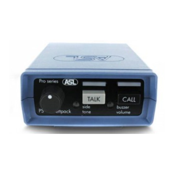
Page 4: Front Panel Controls
Pin 1: shield mic. (GND) Pin 2: +30V DC power wire Pin 2: mic. + Pin 3: audio wire Pin 3: phones + Pin 4: phones – PAGE 3 User Manual PS 19A / Issue 2011 © ASL Intercom BV... -
Page 5: Side Panel Connectors
12 months from date of shipment to the end-user. fault(s) found and a copy of the original suppliers invoice. Faults arising from misuse, unauthorized modifications or accidents are not covered by this warranty. PAGE 4 User Manual PS 19A / Issue 2011 © ASL Intercom BV... -
Page 6: Cabling
CABLING The intercom lines (the ‘party lines’) in an ASL analog intercom system are of the shielded two-conductor microphone cable type. The intercom line connectors are of the XLR-3 type. Audio and Call signals are on pin 3, DC power is on pin 2 and pin 1 is connected to the shield of the cable which functions as the common return for audio and power. -
Page 7: 10.0 Part Line, Technical Concept
10.0 PART LINE, TECHNICAL CONCEPT User stations and power supplies in an ASL (The line impedance is situated in the power intercom system are connected via one or several supply between XLR pin 3 and 1) 'party lines'. This principle has three advantages: A party line offers two way (‘full duplex’) o the use of a single audio line allows communication and consists of standard... -
Page 8: 12.0 Ps 19A Block Diagram
12.0 PS 19A BLOCK DIAGRAM 13.0 SYSTEM CONFIGURATION PAGE 7 User Manual PS 19 A / Issue 2011 © ASL Intercom BV... -
Page 9: 14.0 Earthing Concept
14.0 EARTHING CONCEPT PAGE 8 User Manual PS 19 A / Issue 2011 © ASL Intercom BV...
Need help?
Do you have a question about the PS 19 A and is the answer not in the manual?
Questions and answers